
CB30CECO - Boiler FAGOR - Free user manual and instructions
Find the device manual for free CB30CECO FAGOR in PDF.
| Product Type | Electric Water Heater |
| Brand | Fagor |
| Model | CB30CECO |
| Capacity | 30 liters |
| Power Supply | 230 V AC, 50 Hz |
| Temperature Range | 30 °C to 80 °C |
| ECO Smart Mode | Yes, automatic adjustment based on usage habits |
| Anti-Legionella System | Yes, cycle at 70 °C after 30 days below |
| Vacation Mode | Yes, energy saving with active safety |
| Anti-Corrosion Protection | Protek system (electronic anode) or magnesium anode depending on model |
| Heating Elements | Two, modes single-power, dual, automatic |
| Display | Digital temperature screen |
| Installation | Horizontal or vertical |
| Max. Mains Pressure | 5 bar (pressure reducer required beyond) |
| Safety Valve | Provided, must be connected to the cold water inlet |
| Maintenance | Clean with a soft damp cloth, without abrasives |
| Safety | Automatic shutdown in case of overheating (94 °C), error codes |
| Repairability | Intervention by authorized technical service only |
| Included Accessories | Insulating sleeves, safety valve |
| Manual available in | Multiple languages (FR, EN, ES, etc.) |
Frequently Asked Questions - CB30CECO FAGOR
User questions about CB30CECO FAGOR
0 question about this device. Answer the ones you know or ask your own.
Ask a new question about this device
Download the instructions for your Boiler in PDF format for free! Find your manual CB30CECO - FAGOR and take your electronic device back in hand. On this page are published all the documents necessary for the use of your device. CB30CECO by FAGOR.
USER MANUAL CB30CECO FAGOR
| LIGAÇões ELECTRICAS POR MODELO | ||||||
| MODELOS | Capacidades (litros) | Sonda electrónica | Resistências | Cabo de alimentação | Ânodo electrónico | Bateria recargable |
| CB-30 ECO | 30 | ✓ | ✓ | ✓ | X | X |
| CB-30C ECO | 30 | ✓ | ✓ | ✓ | ✓ | Op |
| CB-50 ECO | 50 | ✓ | ✓ | ✓ | ✓ | Op |
| CB-80 ECO | 75 | ✓ | ✓ | ✓ | ✓ | Op |
| CB-100 ECO | 100 | ✓ | ✓ | ✓ | ✓ | Op |
| CB-150 ECO | 150 | ✓ | ✓ | ✓ | ✓ | Op |
| RB-30 ECO | 30 | ✓ | ✓ | ✓ | X | X |
| RB-30C ECO | 30 | ✓ | ✓ | ✓ | X | X |
| RB-50 ECO | 50 | ✓ | ✓ | ✓ | X | X |
| RB-80 ECO | 75 | ✓ | ✓ | ✓ | X | X |
| RB-100 ECO | 100 | ✓ | ✓ | ✓ | X | X |
| RB-150 ECO | 150 | ✓ | ✓ | ✓ | X | X |

MANTENIMIENTO
DIAGNOSTICO E REPARACOES
A) Falhas
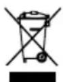
CONGRATULATIONS. You have decided to acquire an electric water heater from FAGOR. We are a prestigious brand and our top priority is fulfilling the needs of our customers, solving them in advance via our innovative state of the art products. Our specialists have carefully manufactured and inspected all our FAGOR electric water heaters in order to provide an ideal response to their needs.
Thank you for the confidence placed in us.
The correct operation of a water heater does not only depend on the quality of the product, but also on its correct installation by a trained professional.
Read this manual carefully before installing and using your water heater in order to achieve its highest performance and extend its life cycle. Keep this manual for future use.
SAFETY AND GENERAL WARNINGS
- The installation and first use must be performed according to these instructions and only by trained professionals. (See the installation section).
- FAGOR water heaters are manufactured and tested according to current regulations.
- This device can be used by children age 8 and older, by physically, sensory or mentally handicapped persons, or persons without proper experience or knowledge, if they have received appropriate supervision or training regarding the safe use of the device and understand the dangers involved. Children should not play with the device. Cleaning and maintenance of the device should not be performed by unsupervised children.
- If the power cable is damaged it must be replaced by the manufacturer, its post-sales department or similarly trained personnel in order to prevent any risks.
- The pressure limiter device must be used often in order to remove lime deposits and verify it is not blocked.
- The water heater does not need any specific maintenance. Before cleaning the device, disconnect it. Scrubbing it with a smooth cloth or moist sponge is enough. Do not use abrasive materials or detergents.
ENVIRONMENT
Legislations and regulations for the protection of the environment are strictly observed (2002/96/EC guideline on electric and electronic waste).
INFORMATION FOR THE CORRECT MANAGEMENT OF RESIDUES FROM ELECTRIC AND ELECTRONIC DEVICES
At the end of its life cycle, it should not be disposed of mixed with general wastes.
It can be delivered, without any cost, to specific waste collection centers, designed by local administrations, or to suppliers that provide this service.

Disposing of the electric device separately serves to prevent possible harmful consequences for environment and health derived from an incorrect disposal, and permits a correct treatment and recycling of its materials, which result in important energy and resources savings.
For further information, contact the local authorities or the store where you acquired the product.
MALFUNCTIONS OR BREAKDOWN
If your water heater presents any malfunctions, immediately disconnect the device from the electrical power supply. Report to the Technical Assistance Service.
In order to facilitate the tasks of the Technical Assistance Service, please provide the following data:
- Heater model.
- Series number.
Purchase date. - Description of the problem.
- Address and phone number.
Full name of the contact person.
INSTALLATION
ACCESORIES
This electric water heater includes the basic installation elements which are found in the packaging, i.e.:
- Insulating bushing for pipes.
Safety valve.
The accessories are located within the packaging.
WALL MOUNTING PROCEDURE
Both the wall and the screws and Rawl-plugs should be capable of withstanding the weight produced by a totally full heater. In case of low thickness walls, the wall should be reinforced.
NOTE.- The placement of the heater must allow access to the supply cable.
LOCATION
The installation procedure is greatly facilitated by being able to locate the unit horizontally or vertically anywhere in the house.
It is advisable, however, to situate the unit as close as possible to where the hot water is to be used as pipe length reduction allows water temperature losses to be prevented.
A minimum 0,5m space should be left underneath the pipe outlet for servicing.
As shown in the drawing 1, when installed horizontally, the input and output pipes must be located on the left.
Should the unit be close to a wall, leave the minimum recommended space for maintenance and servicing operations.
Don't install the heater with its wall mounts againts the floor nor on a horizontal plane.
HYDRAULIC INSTALLATION
NOTE FOR INSTALLERS: the insulating sleeves found inside the packaging, must be located on the inlet/outlet pipes, using teflon on the screw of the pipes. Tightening torque for sleeves: 3.5Kg / m
Before proceeding to the hydraulic connexion, please rinse the connecting pipe in the order to avoid filth from entering inside the electric water heater.
Install the water heater according to the diagrams in figure 1
a) The safety valve supplied with the heater MUST BE INSTALLED on the cold water input pipe.
No other hydraulic accessory can be installed between the safety valve and the cold water inlet pipe.
The outlet of the safety valve must be connected to a drain, whose diameter should be at least identical to inlet pipe. The inclination must be continuous and open, keeping a minimum distance of 20mm , as shown in Figure 1. This pipe must be installed in an environment where freeze is not possible and with a downward slope. Water expands when heated, leaking (at leats a 3% per heating cycle). Do not worry, this is a standard phenomenon.
To empty the heater, operate the safety group hoisting the lever as shown on figure 2. We should act on said lever periodically to prevent it locks and check for proper operation.
b) If the water-supply pressure exceeds 5 bars, a type-approved reducing valve (between 3 or 4 bars) must be installed.
c) In case of plastic piping in the system, please take into account pressure and temperature conditions. Maximum pressure 9 bars and 70^ maximum temperature in standard conditions or 100^ in abnormal conditions when the safety thermostat cuts the energy supply.
ELECTRIC INSTALLATION
All storage water heaters are of 230V AC. Before connecting make sure that the mains supply and unit input features coincide.
The heater's installation procedure is totally straightforward and only requires that Low Voltage Electronic Regulations be met.
For installations in bathrooms and toilets Regulation IEC 60364-7-701 shall be adhered to.
VOLUME OF PROHIBITION: Zone 1 defined in figure 3.
No switches, sockets or lighting fixtures will be installed.
VOLUME OF PROTECTION: Zone 2 defined in figure 3.
No switches will be installed, however safety sockets or sockets protected by a 30mA circuit breaker may be installed.
The boiler should be installed outside the VOLUME OF PROHIBI-TION, in order to prevent water reaching the inside of the appliance. If the boiler has no plug, electrical power should be supplied through a bipolar switch with contact openings of at least 3mm . The installation should be protected with fuses of a calibre corresponding to the absorbed current. An earth connection should be included in every electrical installation. To make this connection, the boiler plug is provided with the appropriate contact, therefore it is enough for the base of the plug to correspond to that supplied with the appliance.
If there is no regulatory "EARTH", we recommend the installation of a ≤ 30mA differential switch.

Fig. 3
This appliance complies with the regulation on Radio-electric Disruption and interferences. WARNING: always service the appliance with official aftersales, included the plug.
CONTROL PANEL

1.- Start-Stop Button
2.- Button for reducing selected temperature
3.- Button for increasing selected temperature
4.- Display: Indicates water temperature
5.- ECO LED: indicates ECO mode is on
6.- Resistor 1 LED: indicates resistor is on
7.- Resistor 2 LED: indicates 2nd resistor is on (for models with power mode)
8.- PROTEK LED: indicates that the corrosion protection and overheat when empty protection are on (for models with electronic anode)
9.- ECO button

Round water heaters
START UP
Filling up. Open the shutoff cock as soon as the heater has been installed. Open the hot water taps. Water appears as soon as the unit fills up completely. Close the taps and check the system for leaks.
Don't connect the heater to the power mains if uncertain as to whether it is full or not.
Electric connection: Plug into the main socket and switch on the main power switch so that the appliance is powered. After switching on the main power switch, press button (1) to switch on the display (4) that indicates the water heater temperature. When a certain quantity of hot water is used, the thermostat connects the heating element again.
Temperature selection: Using buttons (2) to decrease the temperature and (3) to increase the temperature, select the required temperature shown on the display (4). The temperature range is 30eC to 80eC . LED (6) and (7) indicate that the electric resistors are on.
The water heater should be permanently switched on as the control system will ensure that it only operates as required to maintain the selected temperature and any insignificant heat losses are guaranteed by the polyurethane foam heat insulation.
In the event of a power failure the water heater stores the settings prior to the power cut and therefore it is not necessary to press the Start-Stop button (1) again for the water heater to operate.
How to empty the unit. The heater should be fully drained if left unused for extended periods or if subject to freezing hazards where installed. This can be done by means of the safety valve.
Always remember to:
- Cut-off the power supply.
- Shut-off the input cock.
- Open the hot water tap..
FEATURES
ANTI LEGIONELLA (AL) SYSTEM
This is a preventive system activated by default at the factory to prevent the spread of bacteria such as legionella.
When the water temperature falls below 70^ for 30 days, the water heater runs a heating cycle until a temperature of 70 ^ C is reached regardless of the selected temperature setting.
This preventive system can be switched on or off by the user in accordance with that shown in the following table:
| 1- Feature 2- Access. | 3- Switching feature on / off. | 4- What is displayed. | 5- Exit the configuration. |
| Anti-legionella | Press "+" and "-" together for 3 seconds | Press "+" or "-" | On On Off Off |
| Automatically after 5 seconds |
POWER MODE (Square water heaters)
The water heater can be configured to operate with one or two resistors or a combination of both options. The user can select one of the following modes:
- Mono power mode (P1): When heating is required, the water heater activates one of the two resistors alternately, thereby increasing the service life of the components.
- Dual power mode (P2): When heating is required, the water heater activates both resistors at the same time, thereby providing a rapid response to reach maximum power.
- Automatic mode (Au): This mode combines the advantages of the above modes: a longer service life at maximum power. When the water heater detects a significant consumption of hot water, it immediately activates the maximum power by using all the resistors for the heating. When the consumption is low or if the water temperature is slightly lower than the setting temperature, the water heater activates each of the two resistors alternately.
The user can select the required mode by following the steps given in the table below:
| 1- Feature 2- Access. | 3- Switching feature on / off. | 4- What is displayed. | 5- Exit the configuration. |
| Power management | Press "Eco" and "+" together for 3 seconds | Press "+" or "-" | Mono power → |
| Dual power→ | |||
| Automatic → |
Depending on the model, the water heater is fitted with one of the following anti-corrosion protections:
a) Protek: this is an exclusive modulating electronic system which, in combination with the titanium anode, sets the water heater power at values within the ideal corrosion protection zone, thereby guaranteeing the maximum service life of the water heater tank.
The correct operation of the Protek requires that the water heater is permanently connected to a 230 VAC electric power supply, even when the water heater is not operating.
The correct operation of the Protek is indicated by LED (8) which remains permanently lit.
Battery Kit (optional): models equipped with the Protek system can be converted into water heaters for use with the night tariff (or time discriminating tariff), by fitting a Battery Kit (installed by a professional technician). The battery guarantees the power supply to the Protek in the event of a power failure lasting up to 24 hours. In this case the correct operation of the Protek is indicated by LED (8) which flashes.
In the event of a fault in the Protek system, LED (8) switches off completely and the water heater triggers the corresponding fault code on the display (4).
b) Magnesium anode: this is a protection system for the water heater tank using a sacrificial magnesium anode attached to the water heater flange.
VACATION MODE
In the event of a temporary absence or journey, the "vacation mode" is activated by pressing the button (without disconnecting the water heater from the main power supply or switching off the main power supply of the house).
The water heater enters energy-saving mode by deactivating all unnecessary sources of consumption (resistors, display, LED...) and maintaining all the safety features activated (de-icing system, electronic anti-corrosion protection, self-diagnosis...)
De-icing system: The water heater is protected against low temperatures. Whenever the temperature of the accumulated water is less than 5^ , the resistors will automatically start operating until a temperature of 10^ is reached. While the de-icing system is on the message is displayed cyclically.
ECO SMART FUNCTION
The ECO function allows the temperature setting to be automatically adjusted according to the weekly habits of the user. It is activated by pressing the ECO button, or in models without ECO button, the temperature is increased or decreased (using the +/ - buttons) until a value between 65 and 66^ is shown on the display (4).
When the ECO function is on, the "ECO" LED lights up.
INFORMATION FOR THE TECHNICAL SERVICE ELECTRICAL CIRCUIT AND CONNECTIONS DIAGRAM

| ELECTRIC CONNECTIONS BY MODEL | ||||||
| MODELS | Capacities (litres) | Electronic probe | Resistors | Power cable | Electronic anode | Rechargeable battery |
| CB-30 ECO | 30 | ✓ | ✓ | ✓ | X | X |
| CB-30C ECO | 30 | ✓ | ✓ | ✓ | ✓ | Op |
| CB-50 ECO | 50 | ✓ | ✓ | ✓ | ✓ | Op |
| CB-80 ECO | 75 | ✓ | ✓ | ✓ | ✓ | Op |
| CB-100 ECO | 100 | ✓ | ✓ | ✓ | ✓ | Op |
| CB-150 ECO | 150 | ✓ | ✓ | ✓ | ✓ | Op |
| RB-30 ECO | 30 | ✓ | ✓ | ✓ | X | X |
| RB-30C ECO | 30 | ✓ | ✓ | ✓ | X | X |
| RB-50 ECO | 50 | ✓ | ✓ | ✓ | X | X |
| RB-80 ECO | 75 | ✓ | ✓ | ✓ | X | X |
| RB-100 ECO | 100 | ✓ | ✓ | ✓ | X | X |
| RB-150 ECO | 150 | ✓ | ✓ | ✓ | X | X |

Includes this connection

Op Not fitted as standard (optional)
MAINTENANCE
The water heater does not need any specific maintenance. Before cleaning the device, disconnect it. Scrubbing it with a smooth cloth or moist sponge is enough. Do not use abrasive materials or detergents.
Overheating due to a fault in the temperature control is protected by the electronic card, which disconnects the two phases and leaves the water heater resistors without a power supply.
In this case, the Technical Service should be called to repair the fault.
THE MANUFACTURER reserves the right to modify the characteristics and specifications of all products without prion notice.
DIAGNOSIS AND REPAIRS
A) Faults:
The water heater is equipped with a safety system which blocks the appliance if any operating faults are detected, and the corresponding fault code is displayed.
Some of these blocks are automatically reset, while others are safety blocks requiring the manual resetting of the "Safety Reset button" found in the electronic circuit.
The possible faults are listed in the following table:
| FAULT(Display) | PROBLEM | SOLUTIONS |
| E1 Water | heater empty | • Model with Protek: Fill water heater and pressmodels without Protek: Call the technical service. |
| E2 | Electronic temperature probe not connected or faulty | • Call the technical service. |
| E3 Faulty | anode • Call the technical service. | |
| E5 Circuit | • Call the technical service. | |
| E7 Circuit | • Call the technical service. | |
| E8 | Overheating (94 °C) | • Check that the water input temperature is less than 80 °C• If the fault persists, call the technical service. |
| E9 | Temperature probe faulty | • Call the technical service. |
B) Alarms:
When there is a fault in the operation that does not affect safety, the water heater continues to operate, while at the same time indicating the fault type on the display.
The possible alarms are indicated on the following table:
| ALARM (Display) | PROBLEM | SOLUTIONS |
| "Bt" message every 10 seconds | · Battery not found · Battery flat | · Call the technical service. |
| "rE" message every 10 seconds | · Faulty resistor | · Call the technical service. |
HYDRAULICKÁ INSTALACE
ELEKTRICKÁ INSTALACE
Zarizenji dodavano pro 230 V AC. Peclive zkontrolujte, zda napajeci napeti a napeti zarizeni souhlasi. Ohrivac nepotrebuje zaadnou specianyl instalaci; pouze musi splnovat Elektrotechnické predpisy pro nizké napeti.
OBsIe IPEdUYPExKDeHnI PO B3OpACHOCTN
- YctaHOBka N BBOB B 3KcIIyaTaUIO DOJXHbI BblNOJIHTbcr TOLbKO KBaINΦuIPOBaHHbIMn CpeuaIInCTaMn COIaCHO daHHbIM INHCTpyKcIyAM (Cm. pa3dEe «YctaHOBka»).
-ИзгOTOBLEнe ИиСпытAne элЕКТрчecKx BODОHarpeBaTeJIeF FAGOR ПрОЗВОДЯТСАВ COOTBETCTBnC Tpe6OBAHnAМN DeICTByUOuNX HOpM I npaBnI. - 3TO yCTPOIcTBO MOryT nCnOJIb3OBaTb DeTn CTapWe 8 letn IInca C OrpaHnueHHbIMN fN3nueCKnMn, CeHCOPHBIMN JIn6o YmCTBeHHbIMN CnOCO6HOCTaMn INTe, y KOTOpbIX OTCyTCTByOT Heo6XoDnMbIe 3HaHnra INn ONbIT, eCIn INx DeIcTBnRA KOHTPOINpyOTc NIn eCIn OHn IpnOHCTpyKTIPOBaHbI OTHOCInTeJbHO 6e3OnaCHoro nCnOJIb3OBaHnRA YCTPOIcTBa IN OCO3HaIO T B03MOJXhble pNcKn. DeTn He DoJXHbI INpArTb C BOHOHaRpeBaTeIeM. OuNcTKa IN o6CnyJXBaHne aAnpapaT MaOryT BblONHЯTbCSdEybMn TOJbKO NOD npNCMOTpOM B3PocNbIX.
- YTO6bI n36eXaTb ONaChbIX CNTyaCn, 3aMeHa NOBpeKdEHHoro Ka6eJr NNtAHnJa DOLXHa IPOUN3BOuNTbcra N3ROTOBnteJeM, OΦNcuaJIbHOJ Cnyx6oJ NocIePnpOdaJxHOrO O6ClyXuVBaHnjaNN JIn JIncOM C COOTBeTCTByIOUeJ KBaIINΦNkCaunei.
- Heo6xodmo pergyraHo 3aynckaTb B pa6Otu orpaHnUteIb daBleHnA Dn ydaJIeHnHaKnnn n npOBepKn, YTO OH He 3a6JoknpoBaH.
- BODOHarpeBaTeIb He Tpe6yET CneuJIbHOrO TexHnueCKOrO
06cnyKuBaHnI. IpeE npOBeDEHnEM OUnCTKn, Heo6XoJIMo OTKlIOUHTb
ero ot 3JeKTPoPntaHnI. OUnCTKa npOn3BOJNTcMЯrKOJ TpAknO Jnn
BnaJHoI r6koJ 6e3 nCNoJIb3OBAHnI a6pa3INBhblx MaTePnaJIOB IN MOIoUnx
CpeDCTB.
OXPAHA OKPYXKAIOUCEI CPEIbI
3aKohbI n noJIOxKeHnO 03aunTe Okpykaiouei cpebl CTPOrO co6JIoudaIoTcA (DInpeKTnBa 2002/96/EC o6 OTxOax 3NeKtpuueckoro n 3neKTPoHHOrO o6OpuydoBaHn).
MHΦOPMAUJN NO YTNJIIN3ALIIN 3JEKTPNUECKOTO N 3JEKTPPOHHO O6OPYIOBAHNA
Pocne OKOHuaHnCpoka CnyK6bl, daHHbI annapaT He dOnJKeH yTNJIIN3npoBaTcB MecTe C 6bITOBbIMN OTXoJaMn.
Bb moke Te cata B oIN H3 nyKTOB nOphipeHcnpoBaHHoro c6opa OTXODOB, HaxOJaunCBA BeDMCTBe MeCTbIX opraHOB Blactn INI INCTPN6bIOtopy, ppeOCTaBIAHOUe My NIOOHBie yCnyr.
Pa3dJIbHnA yTINI3aun 6bITOBbIX 3JIeKTpnpn6OpOB n03BOJnE rpeDOrBpaNTb BO3MOXhIe HeraTINBHe IocIeCTBnI dIg OkpykaIOSe Cpebl N3DOpOBb JIOde, KOTOpBle MOry T IMeT MeCTo BCNECTBne HeIPpaBnIBHO yTINI3aUN, a TaKKe IO3BOJnE T NOBTOPO HO NCIOJIb3OBAbMb MaTePnaJIbI, BXODaUne B COCTAB 3TNX pIn6OpOB, IN DO6Ntbcra, TaKIM O6pa3OM, CyueCTBeHHoN 3KOHOOMN 3Heprnn n pecypcoB.
YTo6bI NOnUePKHyTb Heo6xOIMOCtB pa3dJIbHOy TnIIIN3aUN, Ha daHHOM aannapaTe HaHeceH 3HaK, npedynpejkaIOUI OTOM, To eRo He cneJeT Bbl6paCbIBaTB B obbHbIe KOHTeHepbl IMycopa.ДЯ NOlyueHn8 60lee nOJpO6HOH INΦOpMaUn CBrXInTECb C MeCTHBIM OprAHOM BlaCTN IN C MaRa3INHom, rDe Bblnpno6pei nn DaHHoe n3dennie.
HENCPABHOCTN I NOJOMKIV
cnyuae c6oB pa6oTe BOHOHaPeBaTeIa, HEmeJIeHHO OTKIOUHTe erO OT CeTn NITAHN I CBXNTecb CO cnyk6oTexHnuecko nOpeKKn.
CteHa n KpeneKhbIe MaTePnaJIb IOnKhbI BblIepKnBaTb Bec BoDoHaRpeBaTeJIa, HAnOJIHeHHoro BOIo. EcII N BoDoHaRpeBaTeJIb KpeNTcra K ToHkO CTHe, To ee Heo6XoDmO yKpeNTb.
BHUMAHNE.-Tenno doJxho 6bItb paCnoJoxKeHO TaK, yTo uHyp nHTaHn BnIka 6bIa doCTynHa.
PA3MELJEHNE
BdoHaRpeBaTeIb MoXHO yCTaHabJIbBaT b KaK rOpN3OHTaJIbHO, TaN BepTnKaJIbHO B IIO6OM MeCe TomeUeHna. BMeCe c TeM, peKoMeHnyETc pa3MeuTa bero KaK MoXHO 6JIuKe K KpaHy nOaunr ropuey BoIb - TaKIM O6pa3OM MoXHO ppeOTbPaTNTb TEJIIOJIoTEpI, CBra3aHHbIe C npoxkJeHm BOIb IIO Tpy6oPBOyDy.
PnBepTKaJIbHOy yCTAHOBKe BOOHaRpeBaTeN OCTaBbTe CHN3y 3a3Op B MINHmym 0,5 M., YTO6bl ObecneuTb CBO6oHbI IOCTyn K KpeEnj Tpy6oPoBOJa N 3JeKTPoNPOBoKe B Cnyae TexHnueckoro 06cnykBaHNn IIN peMOHTa.
Pnp np3oHTaBHO uCTaHOBKe Tpy6Kn IOnaun N OTbOda BOdbI paCnOlaTcra CneBa OTOBoHaRpeBaTeJ, KaK Ioka3aHo Ha pncyHke 1. Ecn npn 3tOM cNeBa HaxoDITcra CteHa, TaKxe OCTaBbTe peKomeHdyembl 3a3Op, UTO6bl IMeTb CBO6oHbI DOCTyn B clyuae texhnueckoro o6cnyxubAHn nn peMOHTa.
3anpeaaetcpaacnoIarabBoOHOHarpeBaTeIbOnopAMn, npedHa3HaueHHbIMn IJIa HaCTeHHoro KpeNexKa, K noJy nnrROPn3oHTaIbHOBIOBepxHocTn.
IIOBOKA TPYONPOBODA
PIMEYAHIE IJRA YCTAHOBUHKA: n30JIauHNoHHBte BTyIKN, NOCTaBJIeMbIe B KOMJIeKTe C BOHOHaTpeBaTeJIeM, BCTaBJIaOTcB Tpy6Kn IOnaun N OTbOa BoIbI, pe3b6a Ha Tpy6kax IMeet TeΦIoHOBOe NOKpbITHe. KpyTuaN MOMENT BTyIok: 3,5 Kr/M.
Ipeen noBokon Tpy6oPBOOa nOauN BObIK BOHOarpeBaTeIO Heo6xOJMO erO OUCTnTb, UTo6bl NOCTOPOHHe YAcTuCbB B Tpy6oPBOOe He nonaII BHyTpB BOHOarpeBaTeJI.
BDOHaRpeBaTeNb DOJXKeH 6bIty cTaHOBHeN B CEHTpaIbHyO cnCTeMy BOOCha6KeHn. (Pnc.1).
a) IpeoxpahntbHbI Klaan, nocTabnemB B KOMnIeKte C BoOnHaRpeBaTelem, OJXHE bItb YCTAHOBJIENB XoJIoHyIO Tpy6ky npdaun BObl.
3aIpeuaetcyaTaHaBnBaTbKaKne-Jin6o DpyrNe KOMnKeKTyUoUe Tpy6OpBoDa MeJy IpeOxAHTeNbHbIM KlaNaHOM N Tpy6kOIOpaUHxOLOHO BObbl.
BbIXoI npEdoxpaHntbHOrO KJIanaHa DoJXeH 6bIT CoeINHeH C Tpy6oB BOIOcINBa, DnAmETp KOtOpO JOnJKe HOBaTb C DnAmETpOM Bcero Tpy6oPBOIDA BOHOHaRpeBaTeA. BbIXoI DoJXeH 6bIT DInHOH He MeHee 20 MM. N IMeTb YKIOH, KaK NOKa3aHO Ha Pnc.1. 3ToT Tpy6oPBOOD DoJXeH 6bIT yCTaHOBJeH C yKIOHOm IN B NOMeUeHN C TempePATypO He HNKe HNYraDycoB.
Bo BpemHaRpeBaHnBa Oda pacuipreTc, YTO npBODNT K BO3HKnHOBeHnO Ha pa6oUx DeTajnx Kaenb BoDbl (OKONO 3% OT mHeoIeOcra o6bE Ma BDoHa KaJdbI cKKn HArpeBa). 3To HopMaJIbHoe ABlHe, OHO He DoJXHO Bac 6ecnokOnTb.
TTo6bl OuHCTnTB TepMoc, Heo6xOIMMo DeIcTBOBaTB Ha rpynnpe 6e3OnacHOCTn npInnoHMma pyUar, KaK Noka3aHo Ha pucyHke 2.Ecn n deiCTBOBaTB Ha yka3aHHbI pyUar nepNoDnueckn, YTo6bl IpeDoTbpaNTb erO fHKcaunn I npOBepntb npabNlbHOCTb pa60tbl.
6) Ecnn daBHeHne B Tpy6oPBOe npeBbIaeaT 5 6ap, To Heo6xOIMO yCTaHOBT b Klaan H NoHNKeHna DaBHeHna (ot 3 do 4 6ap). B) Pn IcNoIb3OBaHm nnactIKOBbIX Tpy6 dnnnoBDOKn BOOpPOBa, CNeDyET IMeTB B BVdy, Ha KaKHe daBHeHn i Tempeatyp OHI paccuHTahbl. MakcImaJIbHoe daBHeHne 9 6aan MaKcImaJIbHaer TempepaTypa 70^ npn HopMaJIbHbIx ycIOBnx 3KcNpYataun nn do 100^ npn HnpabInbHbIX ycIOBuaX, npn 3ToM cpa6aTbIbAet 3aUHTbIy TepMOCTaT, OTKnIOuaET NITAHne BOHOHaRpeBaTeNa.
NOKJIIOUOHEHNE K CETN
Bce moJIeN BOHOHaRpeBaTeNe NODKIOUaIOc K cTeN 230 B nepeMeHHoro ToKa. IpeNd noIKIoueHNem y6eHITecb, YTO yKa3aHHoe dNRA BOHOHaRpeBaTeNa HApJKeHne COOTBeTCTByET IMEIOUeMycB CteN.
IpoueDypa noKlueyHn BOHOHarpeBaTeN K cTeN ABJrEcTc NOHOCbIO pPraMo, HO Heo6xOIMo co6JIIOaTb Tpe6OBaHn IO Hn3KOMy HapjKeHnIO, yka3AHhBie B «JNeKtpoTeXHnueCkN NpaBnax>.
Дяообудованя, устанвьамог в ваньхи Tyanetax, He6xOIMo co6NdaH HopMbI CTahdapTa M3K 60364-7-701.
OBJACTb 3AIPETA: 30Ha 1, yka3aHHa Ha pnc. 3.
YcTaHObKa BblKlIOuAtene, po3eTOK nINOCBETnTeNbHbIX npn6OpOB BblONJIHTbcr He 6yndT.
OBNACTb 3AUHTbl:30Ha2,yka3aHHaHa pnc.3.
BbIKHouaTeHn yCTaHaBnBaTbcr He 6ydyT. Ondako Moryt 6bItb yCTaHOBneHbI 6e3oNaChbIe po3eTKn nn p03eTKn c 3aunTOI aBTOMaTHueCKM BblHouaTeHem Ha 30 mA.
ДлпnpedOBpauHnнОнадиВODыBHytpbYcTpoCTBa6OJIpeDOnKHe yctaHaBnBaTbCBA HBe OBJACTN 3APETA.EcIn 6oJIneP He o6OpydoBAn WTeIeBHO BUNKO, 3NeKTPoNTaHne DOJXHO NODaBaTbCrype3 DByXIOIOCHb BYIKIOUaTeNb C OTBepCTnMn DnKoHTaKTob pa3MePOM He MeHee 3 MM. O6OpydoBAHne DoJXHO 6bITb 3aUHSeHO npEdoxpaHtEnMa n CHOMHaIOM, COOTBeCTByIOUIM NOTpe6bIeMOMy TOky. KaJdA 3NeKTPoUcTaHOBA dONKHa 6bITb CoeINHeHa C 3a3EmJIeHNm.
ДяТAKORO coeINHeHn B WTeNCelbHOB BUNKe 6oJInepa npEDyCMOTpeH COOTBeTCTByIOUm KOHTaKT. TAKIM O6pa3OM, 6yJeT DocTaTOUHO, ecN KOHTaKT OCHOBaHnB BUNK 6yJeT COOTBeTCTBOBaTb KOHTaKtY OCHOBaHnA, npeDyCMOTpeHHOMy dIra O6OpyDoBaHnA.

EcHn cTahdapThoe 3aemHe He npedyCMOTpeHo, peKOMeHdyTeYc yTaHOBnTb DnΦΦePeHuaNbHbN BBkIOuAteNb Ha ≤ 30 MA. DaHHoe n3dennne COOTBeCTByET Tpe6OBaHNm NO paCnPoCTpaHEHNO paNo3JIeKTKPOHHbIX NOMEX N BONH.
BHIMAHHE: cepBnchoe 6cbnyKbHaHne BDOHarpeBaTeI npOn3BoDntb OfNuaNbHbIMN cepBnChbIMN ueHTpAMN mCnoB3OBaTb opunHaHbHbIe KOMnEKeTyOuIe (B TOM uCNe wTenCeNbHyIO BuNKy).

1.-KhONKaIyck-OctaHOBka
2.-KHonka yMeHbWeHnB bI6paHHoTempeaTypb
3.-KhoNka yBelenueHn BbI6paHNo TEmpeaTpyb
4.-DinCnIe: noka3bIbaeT tempeatypy BODi
5.-CBeToiOnEO: noka3bIbaeT, yTo peXIM ECO BKJIIOUey
6.-CBetOIOI ^ 口 (HarpeBaTeBHyI 3JemeHT1NOKa3bBaET,TOHarpeBaTeBHyI 3JemeHTBKJIOUeH
7.-CBetOnIOd «HarpeBaTeNbHbI 3JeMeHT 2»: NOKa3bIbAeT, yTO BtOPOHarpeBaTeNbHbI 3JeMeHT BKJIOUeH (ДЯ MODeJIc a yCTaHOBKO MOUHOCTn)
8.-CBeToIIOI PROTEK: noka3bIbaeT, yTo 3aunTa OT Koppo3nN 3aunTa OT nepeRpeBa BkIoUyeHbI (JnMoJeJI C 3NeKTPuYeCKmU aHOdAmU)
9.- Khonka ECO
HAUJIO PABOTbl
HanoHHe M BOO: Nocye yctAHOBKn BOHOHaRpeBaTeIg OTKpoTe NepenyckHO Klaanah. 3aTeM OTKpoTe KpaHbI c Tropaeey BOo. KaTolbKO BOHOHaRpeBaTeJIb NONHOCTbIO 3aONHHTcB BOO, C KpaHOB NOJET BODa. 3akpoTe KpaHbI n npOBepbTe, HET IIN yTEuKN BObl.
3anpeaetcnoKIOHouatb K cETn BOHOHaRpeBaTeNb,ecn OH He3aONHeHHbI BOOJ.
3neKtpueckoe coeqHHeHn: POKNIOUHTe yCTPOINCTBO K CTeBOI PO3eTKe N BKNIOUHTe NITAHNE, HaxAB TnABHbIM BkIOUaTeJI. IocNe BKNIOUeHN rnaBHO BkIOUaTeJI HAXMITE HA KONky (1), UTO6bl BKNIOUHTb DnCnJIe (4), NOKA3bBAOJUM TemNepaTyP BOHOHarpeBaTeJI. Ipn OXNAJDeHN ROPaey BOI TepMOCTa 3aHOBO BKNIOUaET HarpeBaTeJIbHbIe 3JeMeHTbl.
YctaHObKa TemnepaTypb: YcTaHOBnTe HxKHyTo TemnepaTypy, KaN poka3aHo Ha dncnlee (4), nCOnb3y KhoIKN (2) nnoHHKeHn I KONKn (3) IJn NOBbIeHn TEmnpaTypb. Dnana3oH TemnpaTypb ot 30 eC do 80 eC. CBeToDIObl (6) n (7) NOKa3bIBaHT, YTO HarpeBaTehHbIe 3JeMeHTb BkIIOueHbl.
BdoHaRpeBaTeNb DOnKeH 6bTb BcERda BkIoueH, TAK KAc CnCTema ynpaBHeHnO bcneHT NoepKaHne 3aHaHHo TeMnepaTpby ToIbKO np He6oJbuxN oTepEx TeNna (6laOpaT eTnON30JUuN N3 neHONOHypeTaHa).
Pn c6oe 3neKtpoNTaHnB BOHOHarpeBaTeNb COXpaHReT HAcTpoNKn, NOrTomy Het Heo6xOIMOCtN HaKImaTb KONkY Pnyck-OctahOBka (1) 3aHOBO dIe BKNIOUeHnB BOHOHarpeBaTeJIa
CnB: Ecn BDOHaRpeBaTeB He 6yET NcNoIb3ObaTbCra DoCTaTOUHO DOnIO, a B MeCe erO yCTaHOBKn DOnyCKaETcHn3KaH TemnepaTpya (B T.Y. C O6pa3ObaHnEM Nbda), peKoMeHdyeTcra CInMb BCIO BOHy n3 BDOHaRpeBaTeHa. 3To MoXHo cDenaTb C nOMoub H npEdoxpaHHTbHOro KnaNaHa.
Heo6xOaIMo NOMHHTb:
-OTKIOUHTb BOOHaTpeBaTeJIb OT cETN.
-3akpbitb KpaH noaun BOdbI B Tpy6oipoBOD HarpeBaTeTn.
-OTKpbItb KpaHrOpyeB ODbI Ha HArpeBaTeNe.
ФУHKЦИN
CNUCTEMA AHTN-JIEHNOHEJIJA (AL)
3Ta npofoaikTucecka CnCTema yctaHaBnBaETcHa 3aBOe I NO yMOJuaHIO IIN 3aunTbI OT pacnpocTpahHeHna TaKx 6akTepn, KaK JnerHOJIla.
Ecn TEmnepaTypa BObI onyckaTcH NHe 70 ^ C B TeueHne 30 He, BOHOHaPeBaTeB BXoNT B pexm HArpeBaHn, noka TemnepaTypa He DoCTnraet 70 ^ C Bhe 3aBucmocTo OT 3aDaHHoTemnpaTypbl.
JaHHyIO CNTeMy NOnb3OBaTeJIb MoXET BKNIOUHTb NINBbIKNIOUHTb, KaK yKa3aHO B CNeIyoIe Ta6NIuIe:
PEXKIM IPIPNOCTAHOBKN PA5OTbl
Pn BpeMeHHOM OTbe3e «peKIM npnoCTaHOBKn pa6OtBi» BKJIIOUaETc npn HaxaTn Ha KhoNky (6e3 OTKJIIOUeHn BAoHaIgPeBaTeJr OT OCHOBHOrO NCTOCHNkA NITAHN rIN NOLHOrO OTKJIIOUeHn 3JIeKTpocEtN B Dome).
BdoHaRpeBaTeIb nepeKJIIOuaETcB pexkIM 3KOHOMN 3Heprn: OTKIIIOUaOTcBce HeHyXHbIe NCTOCHNKI
notpe6leHnra 3JeKTPo3Heprn (HarpeBaTeIbHbIe 3JeMeHTbl, DInCpIe, CBeToNDoDbI...), KpOme CNTEm
6e3OnacHOCTn (CnCTema 3aunTbI OT o6JeDEHeHnRA, 3JeKTPoHNa 3aunTa OT KoppO3nn, CaMOJNaHOctNka...)
CnCTema 3aunTbI OT o6JeDEHeHnRA: BDOHaRpeBaTeIb 3aunuEh OT BO3dEChTBn Hn3KoN TempepaTypbl. Ecn
TempepaTypa HaKOpLeHHoB BoDbl HnKe 5 ^ , aBTOMaTIueCKN BKIOUaOTcRA HarpeBaTeIbHbIe 3JeMeHTbl, noka
TempepaTypa He DoCTuHET 10 ^ . Poka CnCTema 3aunTbI OT o6JeDEHeHnPa6oTaet, coo6uEHe OTO6paKaETcRA nepNOduueckn.
ФУHKLДЕECOSMART
Функця ECO no3BONЯET yctpoCTBy aBTOMaTnueckn perylnpOBAbTe TMnepaTpy B COOTBeTCTBnC exKeHeJIbHbIMn npedNoCTeHnA Mn noIb3OBaTeJ.ФунKzur BKIIIOuAeTCr haxaTneM KhoNk ECO.B moJeJx 6e3 KhoNk ECO TempepaTpya NoHxAeTcR NIN NOBbIAeTcR C NOMOuBIO KHOIOK.+/-,NOKa He yCTaHOBNTcR B dHaNa3OHe ot 65do 66^ ,KaK nok3aHo Ha dinCnlee (4).
Korda yHKun ECO BkHueHa, ropnt cBeToaNoD "ECO".
HΦOPMAUДЯЦЕHTPA TEXHnueCKOTo OBCJyXnBAHnA
CXEMA 3JELKTPNUECKOJI CENI IN COEINHEHNI

| эльектейчески COEdинения NO MOДЕЛМ | ||||||
| MOДЕЛМ | Емкость (питрь) | эльектоныдатук | Нагевателные лементы | Кабель пita两级 | эльектоныанод | Аkkумен无所谓овая батурая |
| CB-30 ECO | 30 | ✓ | ✓ | ✓ | X | X |
| CB-30C ECO | 30 | ✓ | ✓ | ✓ | ✓ | Op |
| CB-50 ECO | 50 | ✓ | ✓ | ✓ | ✓ | Op |
| CB-80 ECO | 75 | ✓ | ✓ | ✓ | ✓ | Op |
| CB-100 ECO | 100 | ✓ | ✓ | ✓ | ✓ | Op |
| CB-150 ECO | 150 | ✓ | ✓ | ✓ | ✓ | Op |
| RB-30 ECO | 30 | ✓ | ✓ | ✓ | X | X |
| RB-30C ECO | 30 | ✓ | ✓ | ✓ | X | X |
| RB-50 ECO | 50 | ✓ | ✓ | ✓ | X | X |
| RB-80 ECO | 75 | ✓ | ✓ | ✓ | X | X |
| RB-100 ECO | 100 | ✓ | ✓ | ✓ | X | X |
| RB-150 ECO | 150 | ✓ | ✓ | ✓ | X | X |

BkIIOucaET 3TO coeINHeHne

eINHeHne OTCyTCTByET

He BXoDNT BCTaHapTHyIO KOMnIeKtauIIO (NocTabJIeTcA OTeJbHO)
EXHNUECKOE OBCJYKUBAHNE
BdoHaReBaTeIb He Tpe6yEt CneuaHoro Texnueckoro 06cnyuBaHHa. Ipeep npoBeHeMeM OuchTK, Heo6xoJMo OTKIOUHTb erO OT 3JeKTPoPiTaHHa. OunchKa ppon3BoDITcR MrgkO JpIKoN nIN BlaXHO r6KOe 6e3 NcnoJIb3OBAHn a6pa3NBbIX MaTePnaIOB IN MOIoXh CpeCTB.
3aunta ot neperpeBa B pezylbTaTe OUn6Kn KOHTpOJa oBeCneuNbAetc Ta NekTPOHHO KapToi, KOTopaa OTcoeHHaET DBe a3bl, TTO pNBOIDNT K OKJIIOUeHIO HArpeBaTeIbHbIX JIeMeHToB.
B 3TOM clyuae dIpeMOHTa Heo6xOdmo 6bpaITbcra B CEHTp TexHueCKoro 6cIyKBAHnA.
Pon3BODntelb coxpaHareT 3a c6oB npaBO n3MeHr8 6e3 npedBaNTbHOrO yBeDOMHeHn XapaKTePNCnN i CneuKaCnN CBOeI npOdyKcnn.
ДИАГHOCTИКA И PEMOHТ
A)Own6ka
BdoHaReBaTeIb cHa6xHcCTeMo 6e30NaChOCTn, KOtOpa 6Jokpyet yctpoiCTBO npn 6hApXeHN OUN6OK. Ha dinCnlee OTO6paXaETc COOTBeTCTByUoN KOD OUn6Kn.
HeKoTOpbIe n3 3nX 6nOKOB aBToMaTnueCckn nepe3aRpyxiaOTcA, a HeKoTOpbIe 6nOKu Tpe6yIO pyHyIO nepe3arpy3ky «KNHONKo Be3onacHO nepe3aRpy3Kn), HaxOJaUeICB 3JIeKtPOHHO cENN.
Bo3MOxHbIe OuN6Kn PnUBeIeHbI B HIXKeIeIyIoJe TAbIe:
aRgNgl aLgSll 8y aalal lalal no gao
aolll aull 100 abls y aib jg

JbcXgJbcX
a a a a a a a a a a a a a a a a a a a a a a a a a a a a a a a a a a a a a a a a a a a a
aaii i 1
aessssssssssssssssssssssssssssssssssssssssssssssssssssssssssssssssssssssssssssssssssssssssssssssss
jbswjjb
1
a_k = 12
11jio 0g 0g 0g 0g
-63-
J 100000000000000000000000000000000000000000000
A
LOX1
g
中
g g g g g g g g g g g g g g g g g g g g g g g g g g g g g g g g g g g g g g g g g g g g g g g g g g g g
Jlll Jg aill lI Jg Jk jssll Cx y
goll
J 1
y 1
3Kg1g2g0ll1abaiI:blal
oolololie g wlaogwlaos
3.3 kall y aas gall 2 aebial:laal lbu
30 30
1 3 1 2 3 4 5 6 7 8 9 10 11 12 13 14 15 16 17 18 19 20 21 22 23 24 25 26 27 28 29 30

1
2
3
4
5
6
7
8
9
J
a
aill g g g g g g g g g g g g g g g g g g g g g g
LJyXol no ggea aal ylll 1
a c b a 1 y j 1 1 1 1 1 1 1 1 1 1 1 1 1 1 1
aiai jll bio 100000000000000000000000000000000000000000000000000000000000000
.5555
y blll 3) jll lss:
Cloglaill (7)g (6) uagall yj80 80 aia 30 30 jai jj.4
aLoo aUo
aal lgl 10000000000000000000000000000000000000000000
a a a a a a a a a a a a a a a a a a a a a a a a a a a a a a a a a a a a a a a a a a a a a a a a a a a a a a a a a a a a a a a a a a a a a a a a a a
:Klll lalal yllal lal alal alal alal alal alal alal alal alal alal alal alal alal alal alal alal alal alal alal alal alal alal alal alal alal alal alal alal alal alal alal alal alal alal alal alal alal alal alal alal alal alal alal alal alal alal alal alal alal alal alal all aol 10000000000000000000000000000000000000000000000000000000000000000000000000000000000000
.(4) 8 (8) [Protek] [Bj g Jg
aalllnssaae aagaaeallgdlgaiyaaeall gaiyaaeallnssaaeallgaiyaaeallgaiyaaeallgai
all 1
J 1000000000000000000000000000000000000000000000000000000000000000000000
sllssl
aag aeg aeg aeg aeg aeg aeg aeg aeg [ECO] ydsaaee [Eco] ydsaaee [Eco] ydsaaee [Eco] ydsaaee [Eco] ydsaaee [Eco] ydsaaee [Eco] ydsaaee [Eco] ydsaaee [Eco] ydsaaee [Eco] ydsaaee [Eco] ydsaaee [Eco] ydsaaee [Eco] ydsaaee [Eco] yds aaee [Eco] ydsaaee [Eco] ydsaaee [Eco] ydsaaee [Eco] ydsaaee [Eco] ydsaaee [Eco] ydsaaee [Eco] ydsaaee [Eco] ydsaaee [Eco] ydsaaee [Eco] ydsaaee [Eco] ydsaaee [Eco] ydsaaee [ECO] ydsaaee [Eco] ydsaaee [Eco] ydsaaee [Eco]

a aallll llllllllllllllllllllllllllllllllllllllllllllllllllllllllllllllllllllllllllllllllllllllllllllllllllllllllllllllllllllllllllllll
- Safety valve.
- Easing lever (for draining).
- Discharge pipe of the pressure relief device.
4.Shut off valve. - Pressure reducer: it's necessary installed after the "meter" when the pressure is more than 5kg / cm^2
- Earthed plastic sleeves (supplied with the heater).
FR
10.- Annual electricity consumption
11.- Daily electricity consumption
12.- Temperature setting for the temperature controller
13. - "Smart" value "1": The information on the hot water generation energy efficiency and on the manual power or fuel consumption applies only when the intelligent control system is switched on.
14.- Weekly fue consumption with smart control
15.- Weekly fue consumption withou smart control
16.- Weekly electricity consumption with smart control
17.- Weekly electricity consumption without smart control
18.- Option to only operate during low-demand periods.
19.- Capacity
20.- Mixed water at 40^
FR
"alcl 1000000000000000000000000000000000000000000000000000000
()gSsH
()dailailai jyjai dai 19
()g 16
()
18
19
40 20

Edesa Industrial, S.L.


- MANTENIMIENTO
- DIAGNOSTICO E REPARACOES
- A) Falhas
- SAFETY AND GENERAL WARNINGS
- ENVIRONMENT
- INFORMATION FOR THE CORRECT MANAGEMENT OF RESIDUES FROM ELECTRIC AND ELECTRONIC DEVICES
- MALFUNCTIONS OR BREAKDOWN
- INSTALLATION
- ACCESORIES
- WALL MOUNTING PROCEDURE
- LOCATION
- HYDRAULIC INSTALLATION
- ELECTRIC INSTALLATION
- CONTROL PANEL
- START UP
- FEATURES
- ANTI LEGIONELLA (AL) SYSTEM
- POWER MODE (Square water heaters)
- VACATION MODE
- ECO SMART FUNCTION
- INFORMATION FOR THE TECHNICAL SERVICE ELECTRICAL CIRCUIT AND CONNECTIONS DIAGRAM
- MAINTENANCE
- DIAGNOSIS AND REPAIRS
- A) Faults:
- B) Alarms:
- HYDRAULICKÁ INSTALACE
- ELEKTRICKÁ INSTALACE
- OBsIe IPEdUYPExKDeHnI PO B3OpACHOCTN
- OXPAHA OKPYXKAIOUCEI CPEIbI
- MHΦOPMAUJN NO YTNJIIN3ALIIN 3JEKTPNUECKOTO N 3JEKTPPOHHO O6OPYIOBAHNA
- HENCPABHOCTN I NOJOMKIV
- PA3MELJEHNE
- IIOBOKA TPYONPOBODA
- NOKJIIOUOHEHNE K CETN
- HAUJIO PABOTbl
- ФУHKЦИN
- CNUCTEMA AHTN-JIEHNOHEJIJA (AL)
- PEXKIM IPIPNOCTAHOBKN PA5OTbl
- ФУHKLДЕECOSMART
- HΦOPMAUДЯЦЕHTPA TEXHnueCKOTo OBCJyXnBAHnA
- CXEMA 3JELKTPNUECKOJI CENI IN COEINHEHNI
- EXHNUECKOE OBCJYKUBAHNE
- ДИАГHOCTИКA И PEMOHТ
- A)Own6ka
- aRgNgl aLgSll 8y aalal lalal no gao
- JbcXgJbcX
- 中
- goll
- J
- FR
- Edesa Industrial, S.L.
Brand : FAGOR
Model : CB30CECO
Category : Boiler