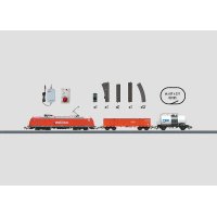
54291 E 44 DB Electric - Model making Märklin - Free user manual and instructions
Find the device manual for free 54291 E 44 DB Electric Märklin in PDF.

Frequently Asked Questions - 54291 E 44 DB Electric Märklin
User questions about 54291 E 44 DB Electric Märklin
0 question about this device. Answer the ones you know or ask your own.
Ask a new question about this device
Download the instructions for your Model making in PDF format for free! Find your manual 54291 E 44 DB Electric - Märklin and take your electronic device back in hand. On this page are published all the documents necessary for the use of your device. 54291 E 44 DB Electric by Märklin.
USER MANUAL 54291 E 44 DB Electric Märklin
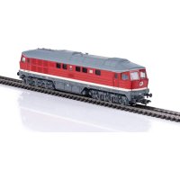
The Class E 44 (144) Electric Locomotive
The economic crisis at the end of the 1920s in the 20th century lead to an ongoing decline in activity on the German State Railroad for further route electrification. At the same time the purchase of new electric locomotives was also put on hold. This gap was filled by the three locomotive builders Bergmann-Elektrizitäts-Werke AG, Maffei- Schwartzkopf-Werke GmbH and Siemens-Schuckert-Werke AG by the development of a new electric locomotive. Each builder developed his own solution that was designated by the German State Railroad as the class E 44 (SSW version), E 44^5 (MSW version) and E 44^20 (BEW version).
While the E 4420 remained a one-off unit and the E 445 was built in only two small groups of 4 units each, the E 44 from Siemens was clearly the most successful development with a quantity of over 180 units. The last of the locomotives in this class were even purchased by the DB, resulting in a total period of manufacture of about 20 years for this locomotive.
These locomotives were used mostly on the Stuttgart - Augsburg route that was electrified starting in 1933. Of the 174 units built before the war, 45 ended up with the German State Railroad (East Germany) and were later designated there as the class 244. The remaining units were acquired by the German Federal Railroad and were operated as the class 144 starting in 1968. A number of these units were modified technically for push/pull operations. One of the critical differences compared to earlier electric locomotive building was the use of two trucks without pilot trucks. This locomotive thereby represents the beginnings of modern locomotive framework designs.
With a maximum speed of 90km / h or 56 mph and up to 2,200 kilowatts or 2,950 horsepower, this successful design was able to fulfill operating requirements well into Era IV. The E 44 was retired by the German Federal Railroad in 1982. For the E 44 units on the DR, 1992 was the last year of operation. Just a handful of these units are still in existence as museum locomotives.
This locomotive has a built-in digital electronic circuit and offers the following features:
Operation with AC power (32 VA transformer) or DC power (max. 18 volts DC) as well as Marklin Delta (6607 Delta-Station only) or Marklin Digital (Motorola format). This locomotive is not designed for operation with locomotive controllers for other systems (example: pulse width control, operation with the Central-Control 1 (6030) or similar systems).
Automatic recognition of conventional and Digital/Delta operation. The choice between AC or DC power in conventional operation is set manually on the circuit board.
80 Digital (4 Delta) addresses can be set with coding switches. Address set at the factory: 44.
- Adjustable maximum speed.
- Headlights change over with the direction of travel and can be turned on and off in Digital operation. During conventional operation the brightness of the headlights depends on the speed of the locomotive. The headlights are on constantly when the locomotive is operated with the Delta Station.
- Only when operated with the 6021 Control-Unit: Sound effects circuit that can be turned on to reproduce prototype sounds that vary with the speed of the locomotive.
Only in operation with the 6021 Control-Unit: Sound effect for a horn can be turned on and off.
- The model has a Telex coupler at both ends that can be uncoupled with a switching command from Márkin Maxi or standard 1 Gauge models with claw couplers, when you are in digital operation with the 6021 Control Unit. You may have operations problems if you use other makes of couplers.
- Minimum radius required for operation: 600mm / 23-5/8". Recommended minimum radius: 1,020 mm / 40-5/32". Automatic coupling or uncoupling is not possible with cars on curves. When traversing curves or turnouts with a radius of 600mm / 23-5/8", the speed of the locomotive must be adjusted to the conditions. Otherwise, derailments are possible.
- This model is suitable for operation on Märklin 1 Gauge track (Maxi or standard 1). You can try running this model on other makes of track, but at your own risk.
2.2 Setting the Mode of Operation or Digital/Delta Address
Step 1: Removing the roof (unscrew whistles, push the roof back and then remove. Page 39).
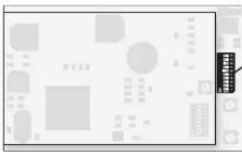
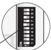
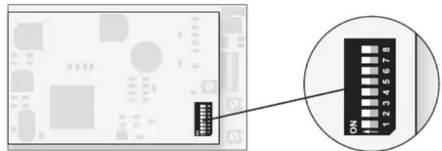
The mode of operation or the Digital/Delta address is set with the 10 coding switches on the digital electronic circuit.
Caution! Do not confuse the 10 coding switches for the mode of operation and for the address on the lower digital circuit board with the 8 coding switches on the upper sound effects circuit board!
2.2.1 Setting the Mode of Operation
Step 2: The analog mode of operation is set with switch 10 (designated "0") of the 10 coding switches.
Switch 10 (0) at off: AC current
Switch 10 (0) at on: DC current
The mode of operation for Márklin Digital or Delta is automatically recognized by the electronic circuit.
Important:
Switch 9 must always be kept at the "off" setting.
2.2.2 Setting Digital/Delta Address
Step 2: The Digital/Delta address is set with switches 1 through 8 of the 10 coding switches.
Example: "44" as the desired address
Switch 6,8: on position
Switch 1,2,3,4,5,7: off position
Important:
The digital addresses 24, 60, 72, and 78 correspond to the four Delta addresses.
Operation


Conventional AC power (off) or DC power (on), depending on the setting.
Digital
| ON | ||||||||
| 1 | 2 | 3 | 4 | 5 | 6 | 7 | 8 | 9 |
| 01 - | 2 | 3 | - | 5 | - | 7 | - | ✘ |
| 02 - | - | 3 | - | 5 | - | 7 | - | ✘ |
| 03 1 | - | - | 4 | 5 | - | 7 | - | ✘ |
| 04 - | 2 | - | 4 | 5 | - | 7 | - | ✘ |
| 05 - | - | - | 4 | 5 | - | 7 | - | ✘ |
| 06 1 | - | - | - | 5 | - | 7 | - | ✘ |
| 07 - | 2 | - | - | 5 | - | 7 | - | ✘ |
| 08 - | - | - | - | 5 | - | 7 | - | ✘ |
| 09 1 | - | 3 | - | - | 6 | 7 | - | ✘ |
| 10 - | 2 | 3 | - | - | 6 | 7 | - | ✘ |
| 11 - | - | 3 | - | - | 6 | 7 | - | ✘ |
| 12 1 | - | - | 4 | - | 6 | 7 | - | ✘ |
| 13 - | 2 | - | 4 | - | 6 | 7 | - | ✘ |
| 14 - | - | - | 4 | - | 6 | 7 | - | ✘ |
| 15 1 | - | - | - | - | 6 | 7 | - | ✘ |
| 16 - | 2 | - | - | - | 6 | 7 | - | ✘ |
| 17 - | - | - | - | - | 6 | 7 | - | ✘ |
| 18 1 | - | 3 | - | - | - | 7 | - | ✘ |
| 19 - | 2 | 3 | - | - | - | 7 | - | ✘ |
| 20 - | - | 3 | - | - | - | 7 | - | ✘ |
| 21 1 | - | - | 4 | - | - | 7 | - | ✘ |
| 22 - | 2 | - | 4 | - | - | 7 | - | ✘ |
| 23 - | - | - | 4 | - | - | 7 | - | ✘ |
| 24 1 | - | - | - | - | - | 7 | - | ✘ |
| 25 - | 2 | - | - | - | - | 7 | - | ✘ |
| 26 - | - | - | - | - | - | 7 | - | ✘ |
| 27 1 | - | 3 | - | 5 | - | - | 8 | ✘ |
Digital
| ON | |||||||||
| 1 | 2 | 3 | 4 | 5 | 6 | 7 | 8 | 9 | 0 |
| 28- | 2 | 3- | 5- | - | 8- | * |
| 29- | - | 3- | 5- | - | 8- | * |
| 301- | - | 4 | 5- | - | 8- | * |
| 31- | 2- | 4 | 5- | - | 8- | * |
| 32- | - | 4 | 5- | - | 8- | * |
| 331- | - | - | 5- | - | 8- | * |
| 34- | 2- | - | 5- | - | 8- | * |
| 35- | - | - | 5- | - | 8- | * |
| 361- | 3- | - | 6- | - | 8- | * |
| 37- | 2 | 3- | - | 6- | 8- | * |
| 38- | - | 3- | - | 6- | 8- | * |
| 391- | - | 4- | 6- | - | 8- | * |
| 40- | 2- | 4- | 6- | - | 8- | * |
| 41- | - | 4- | 6- | - | 8- | * |
| 421- | - | - | 6- | - | 8- | * |
| 43- | 2- | - | 6- | - | 8- | * |
| 44- | - | - | 6- | - | 8- | * |
| 451- | - | 3- | - | - | 8- | * |
| 46- | 2 | 3- | - | - | 8- | * |
| 47- | - | 3- | - | - | 8- | * |
| 481- | - | 4- | - | - | 8- | * |
| 49- | 2- | 4- | - | - | 8- | * |
| 50- | - | 4- | - | - | 8- | * |
| 511- | - | - | - | - | 8- | * |
| 52- | 2- | - | - | - | 8- | * |
| 53- | - | - | - | - | 8- | * |
| 541- | 3- | 5- | - | - | - | * |
Digital
| 55- | 2 | 3 | - | 5 | - | - | - | - | * |
| 56- | - | 3 | - | 5 | - | - | - | - | * |
| 571 | - | - | 4 | 5 | - | - | - | - | * |
| 58- | 2 | - | 4 | 5 | - | - | - | - | * |
| 59- | - | - | 4 | 5 | - | - | - | - | * |
| 601 | - | - | - | 5 | - | - | - | - | * |
| 61- | 2 | - | - | 5 | - | - | - | - | * |
| 62- | - | - | - | 5 | - | - | - | - | * |
| 631 | - | 3 | - | - | 6 | - | - | - | * |
| 64- | 2 | 3 | - | - | 6 | - | - | - | * |
| 65- | - | 3 | - | - | 6 | - | - | - | * |
| 661 | - | - | 4 | - | 6 | - | - | - | * |
| 67- | 2 | - | 4 | - | 6 | - | - | - | * |
| 68- | - | - | 4 | - | 6 | - | - | - | * |
| 691 | - | - | - | - | 6 | - | - | - | * |
| 70- | 2 | - | - | - | 6 | - | - | - | * |
| 71- | - | - | - | - | 6 | - | - | - | * |
| 721 | - | 3 | - | - | - | - | - | - | * |
| 73- | 2 | 3 | - | - | - | - | - | - | * |
| 74- | - | 3 | - | - | - | - | - | - | * |
| 751 | - | - | 4 | - | - | - | - | - | * |
| 76- | 2 | - | 4 | - | - | - | - | - | * |
| 77- | - | - | 4 | - | - | - | - | - | * |
| 781 | - | - | - | - | - | - | - | - | * |
| 79- | 2 | - | - | - | - | - | - | - | * |
| 801 | - | 3 | - | 5 | - | 7 | - | - | * |
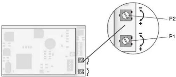
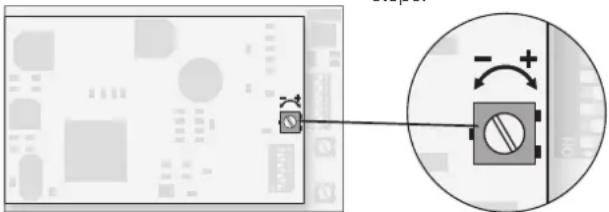
2.3 Setting the Running Characteristics
- Removing the roof (unscrew whistles, push the roof back and then remove. => Page 39).
- You can change the locomotive's running characteristics by changing the settings for the potentiometers on the lower circuit board. These potentiometers have a stop at the end positions. When you encounter resistance when turning the "pots", do not try to turn them further with force.
P1: Acceleration/braking delay (together)
Left stop: minimum delay
Right stop: maximum delay
P2: Maximum speed
Left stop: lowest maximum speed
Right stop: highest maximum speed
Important:
Do not confuse the two potentiometers for setting the running characteristics on the lower digital circuit board with the potentiometer for adjusting the volume of the sound effects on the upper circuit board.
2.4 Operation with the Different Power Systems
2.4.1 Digital
Important:
All of the Marklin central units with the Motorola transmission format can be used to run this locomotive. The full range of functions is only available with the 6021 Control Unit 6021. Functions f1 through f4 cannot be activated if you are using the earlier Central Unit 6020 or a similar version. The indicator for direction of travel is also not present on these units.
The coding switches on the back of the 6021 Control Unit must be set as follows for trouble free operation:
| Switch: 1 | 2 | 3 | 4 | ||
| Setting: on on on | off | ||||
Operating the locomotive with the 6021 Control Unit:
Entering the locomotive address. Turning the speed control knob to the right to the stop increases the locomotive's speed. Turning the speed control knob to the left to the "0" setting decreases the locomotive's speed.
Important:
There will be a delay in the locomotive's reaction to each change in speed, depending on how you have set the acceleration/ braking delay. Turning the speed control knob to the left past the "0" setting: Reverses the locomotive's direction of travel.
Important:
On the 6021 Control Unit two arrows to the right of the address display indicate the direction of travel for the locomotive.
Arrow pointing up:
Locomotive runs forward.
Arrow pointing down:
Locomotive runs in reverse.
Pressing the "function" button: Tums the headlights on.
Pressing the "off" button:
Turns the headlights off.
Pressing button "f2":
Turns the sound effects circuit on (locomotive operating sounds). Pressing button "f2" again turns the sound effects off.
Pressing button "f3":
Turns the sound of a horn on. Now quickly turn this function off by pressing button "f3" again! Otherwise, it can lead to malfunctions.
Pressing button: "f4"
The Telex couplers front and rear are turned on. Pressing button "f4" again turns the Telex couplers off.
Important:
The Telex couplers should not be left on continuously because there is a danger of overheating the coupler solenoids. For that reason they are protected with a circuit against being on too long. Please accustom yourself to turning the Telex couplers on only as long as necessary.
2.4.2 Operating the locomotive with Delta
To operate the locomotive with Märklin Delta you use the Delta-Mobil to select the address, that has been set on the former. The locomotive will run forward when you turn the speed control knob to the right of the center position. Turning the speed control knob to the left of the center position will cause the locomotive to run in reverse. The headlights change direction with the direction of travel and are on all of the time. The maximum power output of the Delta-Station is sufficient to operate 2 to a maximum of 3 single motor locomotives at the same time.
All other functions (sound effects, Telex) are always turned off in Delta operation.
2.4.3 Operating the locomotive on alternating current
When the locomotive is operated with AC power in conventional operation, the 32 VA transformer (no. 6645, 6646, 6647 or 76648) can be used. Locomotive speed is increased by turning the control knob to the right and is decreased by turning the knob to the left. The direction of travel is changed by turning the control knob to the left past the "0" setting.
The command to reverse should be given only to a standing locomotive, never to one in motion. In operation with alternating current the headlights change direction with the direction of travel and are on all of the time. The intensity of the headlights depends on the speed of the locomotive.
All other functions (sound effects, Telex) are always turned off in AC power operation.
2.4.4 Operating the locomotive on direct current
Märklin does not offer DC power packs for 1 Gauge models. Suitable DC power packs are those with a maximum current of ± 18 volts. Direction reversing is done by reversing polarity. The manufacturer's instructions for a particular make of power pack will give directions on how to use it to operate a locomotive.
Tip:
H0 DC power packs supply a maximum voltage of ± 12 volts. This locomotive reaches its full potential at ± 16 volts. H0 DC power packs can therefore be used only with limitations.
In operation with direct current the headlights change direction with the direction of travel and are on all of the time. The intensity of the headlights depends on the speed of the locomotive.
All other functions (sound effects, Telex) are always turned off in DC power operation.
2.5 Adjusting the Sound Effects Circuit
First remove the roof for the following adjustment work. (= > Page 39). The upper circuit board of the two circuit boards is the sound effects electronic circuit on which you can carry out the following adjustments.
2.5.1 Adjusting Volume
Important: This potentiometer is located on the upper sound effects electronic circuit board. Under
no circumstances should you confuse this potentiometer with one of the potentiometers on the lower digital circuit board for adjusting the running characteristics of the locomotive.
Turning the potentiometer to the left: louder
Turning the potentiometer to the right: softer
This potentiometer has a stop at the two end points. Never try to turn the potentiometer with force past these stops.
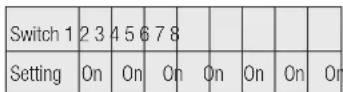
2.5.2 Coding Switches on the Sound Effects Electronic Circuit
Caution: Changing the settings made at the factory can lead to the destruction of the sound effects circuit.
The sound effects electronic circuit is set up for each model with the 8 coding switches. The appropriate settings for your model were made at the factory. No changes in these settings are therefore necessary.
Important: These coding switches are located on the upper electronic circuit for sound effects. Under no circumstances should you confuse them with the 10 coding switches for setting the address and the mode of operation on the lower digital electronic circuit.
The 8 coding switches are set at the factory as follows:
On
2.1 Fonctionnement
3.1 Connections between the track layout and the transformer
Rail joiners must fit well on the rails of the track to which they are joined to avoid voltage drop on the layout. We recommend that you install feeder wires every 2 to 3 meters (7 to 10 feet) using the 5654 feeder clips.
3.2 Operating the locomotive on grades
In contrast to the prototype a locomotive on a model railroad can operate up steeper grades. As a general rule a grade should be no steeper than 3% . In extreme situations a maximum grade of 5% is permissible, keeping in mind that the locomotive's tractive effort will be less. The beginning and the end of the grade must always work gradually up to maximum grade for the route. The maximum allowable difference in grade between two track sections, each with a minimum length of 300mm (11 - 3 / 4^ ) is 1 to 1.5 percent.
With catenary operation:
Pay attention to the ground return marking (star) on the underside of the locomotive!
Removing the roof / Removing the body
Switching to catenary operation
Releasing the pantograph
Changing the wheel pickups
Changing traction tires
Remplacer bandages
Antislipband verrangen
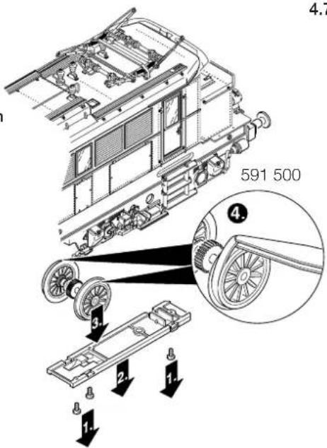
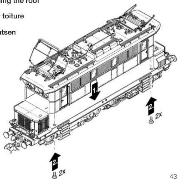
4.7 Dach aufsetzen
Reinstalling the roof
Reposer toiture
Dakplaatsen
This device complies with Part 15 of the FCC Rules.
Operation is subject to the following two conditions:
(1) This device may not cause harmful interference, and
(2) this device must accept any interference received, including interference that may cause undesired operation.