55725 BR 212 DB Diesel - Model making Märklin - Free user manual and instructions
Find the device manual for free 55725 BR 212 DB Diesel Märklin in PDF.

Frequently Asked Questions - 55725 BR 212 DB Diesel Märklin
User questions about 55725 BR 212 DB Diesel Märklin
0 question about this device. Answer the ones you know or ask your own.
Ask a new question about this device
Download the instructions for your Model making in PDF format for free! Find your manual 55725 BR 212 DB Diesel - Märklin and take your electronic device back in hand. On this page are published all the documents necessary for the use of your device. 55725 BR 212 DB Diesel by Märklin.
USER MANUAL 55725 BR 212 DB Diesel Märklin
Different locomotive models to be built in subsequent years were defined in the German Federal Railroad's first type classification program in 1955:
V 60 for switching work
V 100 for mixed branchline service
V 160 for light service on main lines
V 200 for medium service on amin lines
V 320 for heavy service on main lines
Development of the V 100 was started in 1956. From 1958 on a total of 364 class V100^10 (later class 211) locomotives were delivered. This locomotive was subsequently provided with a more powerful motor and additional units were produced with modifications as the V 100^20 (later class 212, previously in the Markin assortment as numbers 5772 or 5573).
The V 100 was intended to replace chiefly the steam locomotive classes 64, 74 and 86 in the DB's restructuring plans. It was employed almost everywhere in Germany on non-electrified routes. It has an output of 808 kilowatts (1,100 horsepower) and a maximum speed of 100km/h (approx. 63 mph).
The V 100 was designed with trucks in the interests of smoother running and better negotiation of curves. The center cab is equipped with two controllers.
This locomotive has proven itself very well on the DB as a jack-of-all-trades. In the 1980s a number of these units were sold to foreign railroads and private lines. At present only the class 212 is still on the motive power roster of the German Railroad, Inc.
A whole series of these locomotives began their second career on different privately owned railroads or track laying firms.
V100
This locomotive has a built-in digital electronic circuit and offers the following features:
- Optional conventional operation (AC power with 32 VA transformer or DC power [max. +/−18 volts DC]), operation with Märklin Delta (only with the 6607 Delta Station), Märklin Digital (Control Unit) or Märklin Systems (Mobile Station or Central Station). This locomotive is not designed for operation with locomotive controllers for other systems (example: pulse width control, operation with the Central Control 1 (6030) or similar systems).
Automatic recognition of conventional operation and multi-train operation. The choice between AC or DC power in conventional operation is set manually on the circuit board.
80 Märklin Systems / Digital (4 Delta) addresses can be set with coding switches. Address set at the factory: 12.
- Adjustable maximum speed.
- Adjustable acceleration/braking delay. The electronic circuit for the locomotive is designed in such a way that the braking delay will not work in conventional operation.
-
Headlights change over with the direction of travel in operation with the Control Unit, the Mobile Station, or the Central Station and can be turned on/off. During conventional operation the brightness of the headlights depends on the speed of the loco-motive. The headlights are on constantly when the loco-motive is operated with the Delta Station.
Built-in sound effects circuit, on which the locomotive's operating sounds or the separate sound of a horn can be turned on only in operation with the Control Unit, the Mobile Station, or the Central Station. -
The acceleration and braking delay that has been set can be turned down to a minimum as a controllable function when operating the locomotive with the Control Unit, the Mobile Station, or the Central Station. This gives you better control of the locomotive for switching operations.
Minimum radius for operation: 1.020 mm / 40-3/16". - This model has been developed for operation on the Märklin 1 Gauge track system. You incur your own risk operating it on other track systems.
2
Operation
2.2 Setting Locomotive Parameters
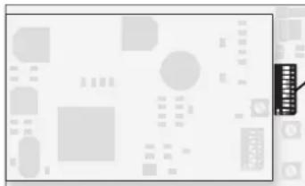
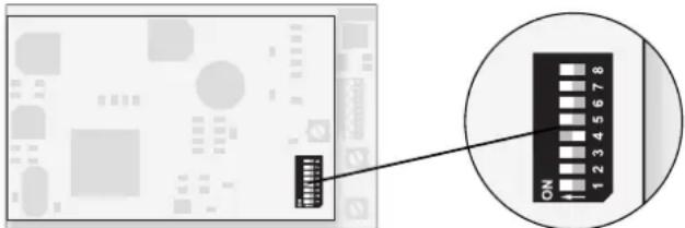
The mode of operation and the multi-train address are set with the 10 coding switches on the multi-train electronic circuit.
Caution! Do not confuse the 10 coding switches for the mode of operation and for the address on the lower digital circuit board with the 8 coding switches on the upper sound effects circuit board!
2.2.1 Setting the Mode of Operation
- Removing the body (= > page 42).
- Setting the coding switches.
Switch 10 (0) at off: Operation with AC power
Switch 10 (0) at on: Operation with DC power
The multi-train operation mode (Digital / Delta / Marklin Systems) is automatically recognized.
2.2.2 Setting a Multi-Train Address
- Removing the body ( > page 42).
- Set the desired address with switches 1 to 8.
Example: 12 is the desired address.
Switches 1,4,6,7 at on. Switches 2,3,5,8 at off.
Important: Switch 9 must always be set at off.
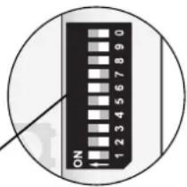


Conventional AC power (off) or DC power (on), depending on the setting.
| Digital | ON | |||||||||
| 1 | 2 | 3 | 4 | 5 | 6 | 7 | 8 | 9 | 0 | |
| 01- | 2 | 3 | - | 5 | - | 7 | - | - | - | ★ |
| 02- | - | 3 | - | 5 | - | 7 | - | - | - | ★ |
| 031- | - | - | 4 | 5 | - | 7 | - | - | - | ★ |
| 04- | 2 | - | 4 | 5 | - | 7 | - | - | - | ★ |
| 05- | - | - | 4 | 5 | - | 7 | - | - | - | ★ |
| 061- | - | - | - | 5 | - | 7 | - | - | - | ★ |
| 07- | 2 | - | - | 5 | - | 7 | - | - | - | ★ |
| 08- | - | - | - | 5 | - | 7 | - | - | - | ★ |
| 091- | - | 3 | - | - | 6 | 7 | - | - | - | ★ |
| 10- | 2 | 3 | - | - | 6 | 7 | - | - | - | ★ |
| 11- | - | 3 | - | - | 6 | 7 | - | - | - | ★ |
| 121- | - | - | 4 | - | 6 | 7 | - | - | - | ★ |
| 13- | 2 | - | 4 | - | 6 | 7 | - | - | - | ★ |
| 14- | - | - | 4 | - | 6 | 7 | - | - | - | ★ |
| 151- | - | - | - | - | 6 | 7 | - | - | - | ★ |
| 16- | 2 | - | - | - | 6 | 7 | - | - | - | ★ |
| 17- | - | - | - | - | 6 | 7 | - | - | - | ★ |
| 181- | - | 3 | - | - | - | 7 | - | - | - | ★ |
| 19- | 2 | 3 | - | - | - | 7 | - | - | - | ★ |
| 20- | - | 3 | - | - | - | 7 | - | - | - | ★ |
| 211- | - | 4 | - | - | - | 7 | - | - | - | ★ |
| 22- | 2 | 4 | - | - | - | 7 | - | - | - | ★ |
| 23- | - | 4 | - | - | - | 7 | - | - | - | ★ |
| 241- | - | - | - | - | - | 7 | - | - | - | ★ |
| 25- | 2 | - | - | - | - | 7 | - | - | - | ★ |
| 26- | - | - | - | - | - | 7 | - | - | - | ★ |
| 271- | - | 3 | - | 5 | - | 8 | - | - | - | ★ |
| Digital | ON | ||||||||
| 1 | 2 | 3 | 4 | 5 | 6 | 7 | 8 | 9 | |
| 28 | - | 3 | - | 5 | - | - | 8 | - | * |
| 29 | - | - | 3 | - | 5 | - | - | 8 | - |
| 30 | 1 | - | - | 4 | 5 | - | - | 8 | - |
| 31 | - | 2 | - | 4 | 5 | - | - | 8 | - |
| 32 | - | - | 4 | 5 | - | - | 8 | - | * |
| 33 | 1 | - | - | 5 | - | - | 8 | - | * |
| 34 | - | 2 | - | - | 5 | - | - | 8 | - |
| 35 | - | - | - | 5 | - | - | 8 | - | * |
| 36 | 1 | - | 3 | - | - | 6 | - | 8 | - |
| 37 | - | 2 | 3 | - | - | 6 | - | 8 | - |
| 38 | - | - | 3 | - | - | 6 | - | 8 | - |
| 39 | 1 | - | - | 4 | - | 6 | - | 8 | - |
| 40 | - | 2 | - | 4 | - | 6 | - | 8 | - |
| 41 | - | - | - | 4 | - | 6 | - | 8 | - |
| 42 | 1 | - | - | - | - | 6 | - | 8 | - |
| 43 | - | 2 | - | - | - | 6 | - | 8 | - |
| 44 | - | - | - | - | - | 6 | - | 8 | - |
| 45 | 1 | - | 3 | - | - | - | - | 8 | - |
| 46 | - | 2 | 3 | - | - | - | - | 8 | - |
| 47 | - | - | 3 | - | - | - | - | 8 | - |
| 48 | 1 | - | - | 4 | - | - | - | 8 | - |
| 49 | - | 2 | - | 4 | - | - | - | 8 | - |
| 50 | - | - | - | 4 | - | - | - | 8 | - |
| 51 | 1 | - | - | - | - | - | - | 8 | - |
| 52 | - | 2 | - | - | - | - | - | 8 | - |
| 53 | - | - | - | - | - | - | - | 8 | - |
| 54 | 1 | - | 3 | - | 5 | - | - | - | * |
| Digital | ON | |||||||||
| 1 | 2 | 3 | 4 | 5 | 6 | 7 | 8 | 9 | 0 | |
| 55- | 2 | 3 | - | 5 | - | - | - | - | - | * |
| 56- | - | 3 | - | 5 | - | - | - | - | - | * |
| 57 | 1 | - | 4 | 5 | - | - | - | - | - | * |
| 58- | 2 | - | 4 | 5 | - | - | - | - | - | * |
| 59- | - | - | 4 | 5 | - | - | - | - | - | * |
| 60 | 1 | - | - | 5 | - | - | - | - | - | * |
| 61- | 2 | - | - | 5 | - | - | - | - | - | * |
| 62- | - | - | - | 5 | - | - | - | - | - | * |
| 63 | 1 | - | 3 | - | 6 | - | - | - | - | * |
| 64- | 2 | 3 | - | - | 6 | - | - | - | - | * |
| 65- | - | 3 | - | - | 6 | - | - | - | - | * |
| 66 | 1 | - | 4 | - | 6 | - | - | - | - | * |
| 67- | 2 | - | 4 | - | 6 | - | - | - | - | * |
| 68- | - | - | 4 | - | 6 | - | - | - | - | * |
| 69 | 1 | - | - | - | 6 | - | - | - | - | * |
| 70- | 2 | - | - | - | 6 | - | - | - | - | * |
| 71- | - | - | - | - | 6 | - | - | - | - | * |
| 72 | 1 | - | 3 | - | - | - | - | - | - | * |
| 73- | 2 | 3 | - | - | - | - | - | - | - | * |
| 74- | - | 3 | - | - | - | - | - | - | - | * |
| 75 | 1 | - | 4 | - | - | - | - | - | - | * |
| 76- | 2 | - | 4 | - | - | - | - | - | - | * |
| 77- | - | - | 4 | - | - | - | - | - | - | * |
| 78 | 1 | - | - | - | - | - | - | - | - | * |
| 79- | 2 | - | - | - | - | - | - | - | - | * |
| 80 | 1 | - | 3 | 5 | - | 7 | - | - | - | * |
2
Operation
2.2.3 Setting the Running
Characteristics Parameters
- Removing the body (= > page 42).
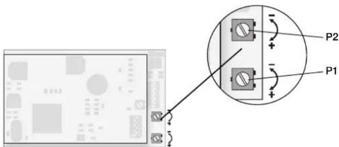
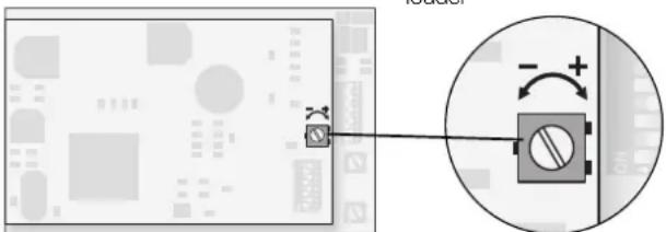
- The respective running characteristics can be changed by changing the setting on the potentiometers. These potentiometers have a stop at the end positions. When you encounter resistance when turning the "pots", do not try to turn them further with force.
P1: Acceleration / braking delay (together)
Left stop: minimum delay
Right stop: maximum delay
P2: Maximum speed
Left stop:
lowest maximum speed
Right stop:
highest maximum speed
Important:
Do not confuse the two potentiometers for setting the running characteristics on the lower digital circuit board with the potenti
meter for adjusting the volume of the sound effects on the upper circuit board.
2.3 Operations with Individual Power Systems
The model is designed for optional operation with Märklin Systems (Mobile Station or Central Station), Märklin Digital (only with the Control Unit as a Central Unit), Märklin Delta, AC power (only with the Märklin Transformer 32 VA), or DC power (power pack with a maximum voltage of +/-18 volts DC). Damages caused by operating the locomotive with another operating system will be viewed as taking place in a non-authorized operating status and therefore are not covered by the manufacturer's warranty. The consumer assumes all responsibility for damages resulting from this situation.
2.3.1 Operation with the Mobile Station / Central Station
Please read the instructions for the Mobile Station or Central Station to enter this locomotive into the locomotive list. Please use the item number for the locomotive found on its packaging to call it up from the database. The following auxiliary functions are available on this locomotive:
- Turning headlights on/off that change over with the direction of travel
- Turning locomotive operating sounds (motor, auxiliary appliances, etc.) on/off
- Turning the sound of a horn on/off
- Minimizing the acceleration / braking delay
2.3.2 Operation with Digital
Important:
All of the Märklin central units with the Motorola transmission format can be used to run this locomotive. The full range of functions is only available with the 6021 Control Unit 6021. Functions f1 through f4 cannot be activated if you are using the earlier Central Unit 6020 or a similar version. The indicator for direction of travel is also not present on these units.
The coding switches on the back of the Control Unit 6021 must be set as follows for trouble free operation:
| Switch: 1 | 2 | 3 | 4 | ||
| Setting: on on on | off | ||||
Operating the locomotive with the Control Unit 6021:
Entering the locomotive address. Turning the speed control knob to the right to the stop increases the locomotive's speed. Turning the speed control knob to the left to the "0" setting decreases the locomotive's speed.
Important:
There will be a delay in the locomotive's reaction to each change in speed, depending on how you have set the acceleration/ braking delay.
Turning the speed control knob to the left past the "0" setting: Reverses the locomotive's direction of travel.
Important:
On the Control Unit 6021 two arrows to the right of the address display indicate the direction of travel for the locomotive.
Arrow pointing up:
Locomotive runs forward.
Arrow pointing down:
Locomotive runs in reverse.
Pressing the "function" button:
Turns the headlights on.
Pressing the "off" button:
Tums the headlights off.
Pressing button "f2":
Turns the sound effects circuit on (locomotive operating sounds).
Pressing button "f2" again turns the sound effects off.
Pressing button "f3":
Turns the sound of a horn on. Now quickly turn this function off by pressing button "f3" again! Otherwise it can lead to malfunctions.
Starting status:
Indicator LED above button "f4" is off: Pressing button "f4" does the following: Minimizes the acceleration and braking delay that has been set.
Starting status:
Indicator LED above button "i4" is on: Pressing button "i4" does the following: Tums the acceleration and braking delay that has been set on the digital electronic circuit back on.
2.3.3 Running the Locomotive with Delta
To operate the locomotive with Märklin Delta you use the Delta Mobil to select the address, that has been set on the former. The locomotive will run forward when you turn the speed control knob to the right of the center position. Turning the speed control knob to the left of the center position will cause the locomotive to run in reverse. The headlights change direction with the direction of travel and are on all of the time. The maximum power output of the Delta Station is sufficient to operate 2 to a maximum of 3 single motor locomotives at the same time.
All other functions (sound effects) are always turned off in Delta operation.
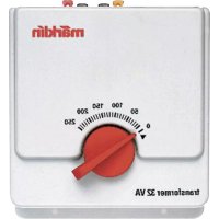
2.3.4 Operating with AC Power
When the locomotive is operated with AC power in conventional operation, the 32 VA transformer (no. 6645, 6646, 6647 or 76648) can be used. Locomotive speed is increased by turning the control knob to the right and is decreased by turning the knob to the left. The direction of travel is changed by turning the control knob to the left past the "0" setting.
The command to reverse should be given only to a standing locomotive, never to one in motion. In operation with alternating current the headlights change direction with the direction of travel and are on all of the time. The intensity of the headlights depends on the speed of the locomotive.
All other functions (sound effects) are always turned off in AC power operation.
2.3.5 Operating with DC Power
Märklin does not offer DC power packs for 1 Gauge models. Suitable DC power packs are those with a maximum current of ± 18 volts. Direction reversing is done by reversing polarity. The manufactureris instructions for a particular make of power pack will give directions on how to use it to operate a locomotive.
Tip:
H0 DC power packs supply a maximum voltage of ± 12 volts. This locomotive reaches its full potential at ± 16 volts. H0 DC power packs can therefore be used only with limitations.
In operation with direct current the headlights change direction with the direction of travel and are on all of the time. The intensity of the headlights depends on the speed of the locomotive.
All other functions (sound effects) are always turned off in DC power operation.
2.4 Adjusting the Sound Effects Circuit
Remove the locomotive body (= > Page 42). The upper circuit board of the two circuit boards is the sound effects electronic circuit on which you can carry out the following adjustments.
2.4.1 Adjusting Volume
Important: This potentiometer is located on the upper sound effects electronic circuit board.
Under no circumstances should you confuse this potentiometer with one of the potentiometers on the lower digital circuit board for adjusting the running characteristics of the locomotive.
Turning the potentiometer to the left: softer
Turning the potentiometer to the right: louder
This potentiometer has a stop at the two end points. Never try to turn the potentiometer with force past these stops.
2.4.2 Coding Switches on the Sound Effects Electronic Circuit
The sound effects electronic circuit is set up for each model with the 8 coding switches. The appropriate settings for your model were made at the factory. No changes in these settings are therefore necessary.
Important: These coding switches are located on the upper electronic circuit for sound effects. Under no circumstances should you confuse them with the 10 coding switches for setting the address and the mode of operation on the lower digital electronic circuit.
The 8 coding switches are set at the factory as follows:
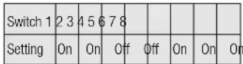
On
2.1 Fonctionnement
3.1 Connections between the track layout and the transformer
Rail joiners must fit well on the rails of the track to which they are joined to avoid voltage drop on the layout. We recommend that you install feeder wires every 2 to 3 meters (7 to 10 feet) using the 5654 feeder clips.
3.2 Operating the locomotive on grades
In contrast to the prototype a locomotive on a model railroad can operate up steeper grades. As a general rule a grade should be no steeper than 3% . In extreme situations a maximum grade of 5% is permissible, keeping in mind that the locomotive's tractive effort will be less. The beginning and the end of the grade must always work gradually up to maximum grade for the route. The maximum allowable difference in grade between two track sections, each with a minimum length of 300 mm (11-3/4") is 1 to 1.5 percent.
4.1 Removing the body
- Remove the four mounting screws on the bottom of the model.
- Now the complete body can be removed.
Important!
- Do not try to grasp the body in the area of the two doors.
- When putting the body back on, be careful that the light bulbs are not bent and destroyed by the partition wall in the body.
Lubrication after 40 hours of operation
Changing light bulbs
Changing pick-up shoes
4.6 Changing couplers
The original claw coupler can be exchanged for a reproduction prototype coupler when the locomotive is to be put on display.
4.6 Remplacer I'attelage
This locomotive can also be used outdoors. We do not recommend running the locomotive in bad weather (snow or rain). The mechanism and the electronic circuit are protected against spraying water. The locomotive cannot be run through water.
We recommend that you check the locomotive over after running in outdoors and that you dry it with a cloth or clean in with a brush if necessary. Never clean the locomotive with running water.
Important: Cleaning fluids can attack the finish and lettering for the locomotive and damage them.
This device complies with Part 15 of the FCC Rules.
Operation is subject to the following two conditions:
(1) This device may not cause harmful interference, and
(2) this device must accept any interference received, including interference that may cause undesired operation.