
U6081CH - Broom ROTEL - Free user manual and instructions
Find the device manual for free U6081CH ROTEL in PDF.
| Product type | Cordless stick vacuum |
| Brand | Rotel |
| Model | U6081CH |
| Rated voltage | 100-240 V |
| Rated frequency | 50/60 Hz |
| Rated power | 95 W |
| Battery type | Lithium-ion (built-in) |
| Estimated runtime | Approximately 20-30 minutes |
| Charging time | Approximately 4-5 hours |
| Dust cup capacity | Approximately 0.5 L |
| Filter type | Washable HEPA filter |
| Main functions | Hand vacuum, rotating brush, crevice tool |
| Usage | Household only, for hard floors and carpets |
| Noise level | Approximately 75 dB (estimated) |
| Weight | Approximately 3.5 kg (estimated) |
| Dimensions (approx.) | 120 cm (height) x 25 cm (width) x 15 cm (depth) |
| Included accessories | Charger, base, floor brush, crevice tool, adapter |
| Maintenance | Clean dust cup and filter after each use |
| Safety instructions | Do not vacuum liquids, keep away from children, unplug before cleaning |
| Spare parts | HEPA filter, brush, dust cup available from retailers |
| Warranty | Manufacturer's warranty (repair or replacement subject to conditions) |
| Disposal | Do not dispose of with household waste, follow WEEE directive |
Frequently Asked Questions - U6081CH ROTEL
User questions about U6081CH ROTEL
0 question about this device. Answer the ones you know or ask your own.
Ask a new question about this device
Download the instructions for your Broom in PDF format for free! Find your manual U6081CH - ROTEL and take your electronic device back in hand. On this page are published all the documents necessary for the use of your device. U6081CH by ROTEL.
USER MANUAL U6081CH ROTEL
natural_image
Red and black vacuum cleaner with handle, standing upright (no visible text or symbols)• wEBRàUxHSàNWEISUNwl
• MODE D'EMPLOI
• ISTRUZIONI PER L'USO
• INSTRUCTIONS FOR USE
CE
RoHS
SENS eRecycling

• SxHEMATISxHE DARSTELLUNw
- Vue d'ensemble
• Diagramma della struttura - Structure diagram
Deutsch yrançais Italiano English
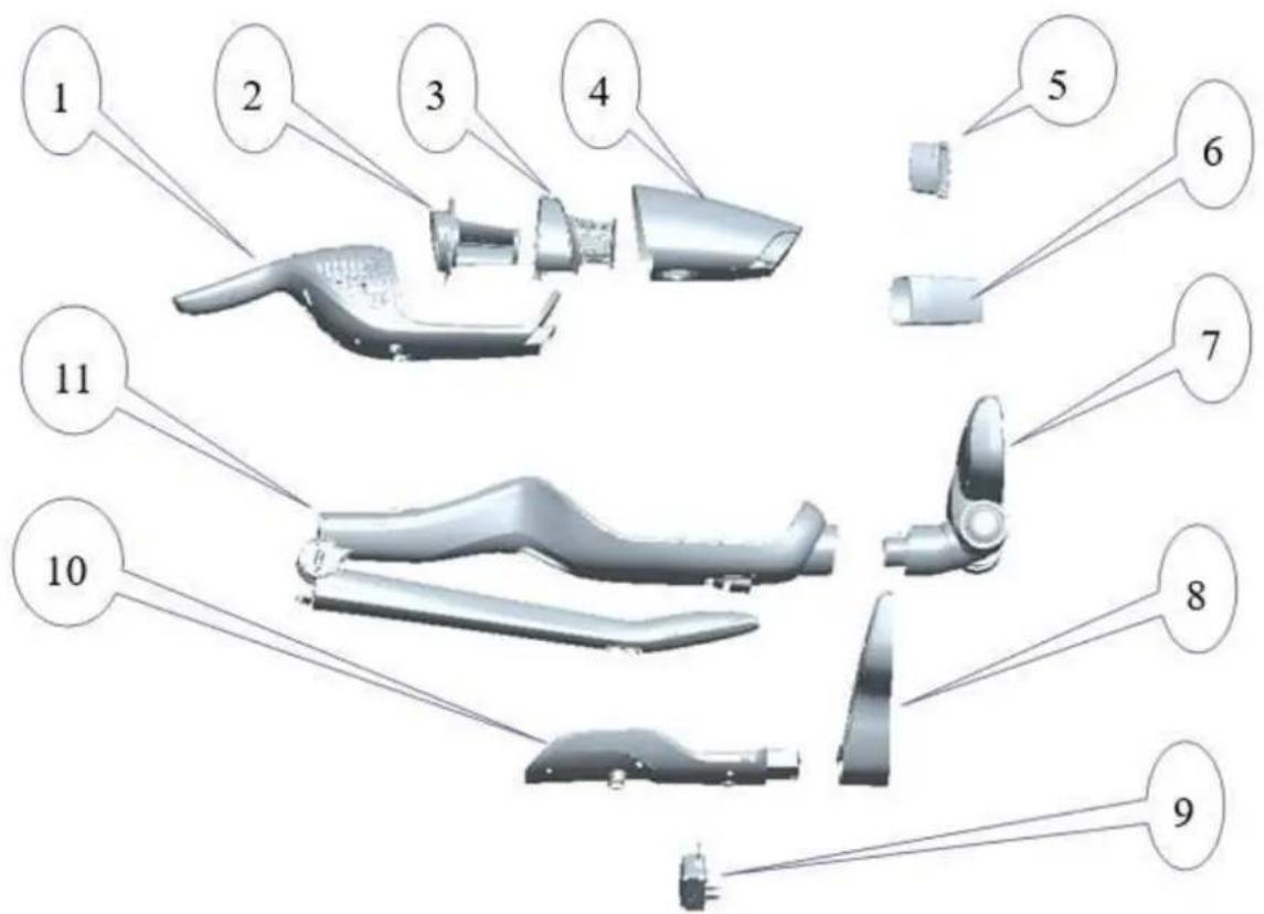
- Handeinheit
- HEPA-Filter
- Filterabdeckung
- Staubbehälter
- Polsterdüse
- Fugendüse
- Bodendüse
- Ladegerät-Sockel
- Adapter
- Ladegerät
-
Gehäuse
-
Aspirateur à main
- Filtre HEPA
- Couvercle du filtre
- Bac collecteur de poussière
- Suceur pour meubles
- Suceur plat
- Suceur
- Socle du chargeur
- Adaptateur
- Chargeur
-
Corps
-
Sottounità
- Filtro HEPA
- Copertura del filtro
- Recipiente per la polvere
- Bocchetta per tappezzeria
- L'ugello per fughe
- Bocchetta di aspirazione
- Supporto caricatore
- Adattatore
- Caricatore
-
Corpo
-
Sub-unit
- HEPA filter
- Filter cover
- Dust cup
- Upholstery nozzle
- Rigid crevice tool
- Floor brush
- Charger stand
- Adapter
- Charger
- Body
TECHNISCHE DATEN
natural_image
Technical line drawing of a mechanical component with no visible text or symbols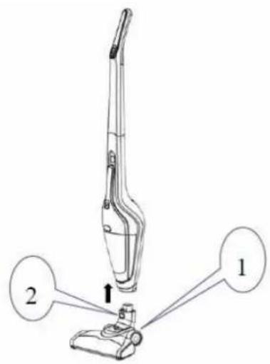
natural_image
Three technical line drawings of a mechanical bracket assembly, showing front, side, and top views with no text or symbols.• BETRIEBSANLEITUNw
10
- àNLEITUNwIZUMILàqENlqESlwERÄTESI
natural_image
Diagram showing two mechanical device setups with cable and connector, no text or symbols present• REINIwUNwlUNqlWàRTUNwl
natural_image
Technical line drawing of a mechanical component with a numbered callout (3), no readable text or symbols present.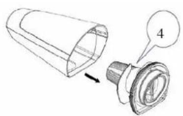
natural_image
Technical line drawing of a mechanical component with a cylindrical part and a flanged base, showing an arrow indicating direction (no text or symbols present)natural_image
Line drawing of a handbag with three views and arrows indicating process steps (no text or symbols)natural_image
Technical line drawing of a mechanical gear assembly with teeth and shaft (no text or symbols)natural_image
Technical line drawing of a mechanical component with two views: top shows internal structure, bottom shows assembly (no text or symbols)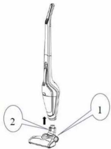
natural_image
Technical line drawing of a mechanical component with an arrow indicating assembly or disassembly (no text or symbols present)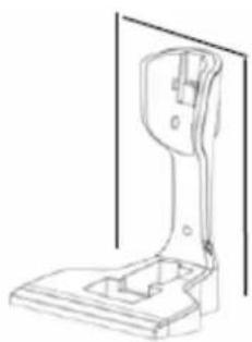
natural_image
Technical line drawing of a mechanical bracket or support structure (no text or symbols)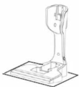
natural_image
Technical line drawing of a mechanical lever assembly (no text or symbols)• INSTRUCTIONS D'UTILISATION
• INSTRUxTIONSlqElRExHàRwEl
natural_image
Diagram showing two identical mechanical devices connected by wires, one with a cable and arrow indicating rotation (no text or symbols present)natural_image
Technical line drawing of a mechanical component with a numbered callout (no text or symbols present)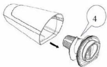
natural_image
Technical illustration of a mechanical component with a cylindrical part and a flanged base, showing a close-up view (no text or symbols)natural_image
Diagram showing a hand holding a small object with arrows indicating transformation or assembly (no text or symbols present)natural_image
Technical line drawing of a mechanical gear or shaft assembly (no text or symbols)natural_image
Three technical line drawings of a mechanical bracket assembly, showing a step-down view from top to front (no text or symbols present)• ISTRUZIONI D'USO
• ISTRUZIONIIqIlxàRIxàl
natural_image
Diagram showing two mechanical device setups with cable and connector, no text or symbols present• PULIZIÀIEIMÀNUTENZIONEI
natural_image
Technical line drawing of a mechanical component with a numbered callout (no text or symbols present)
natural_image
Technical illustration of a mechanical component with a cylindrical part and a flanged base, showing a numbered callout (no text or symbols present)natural_image
Line drawing of a handbag with three views and arrows indicating process (no text or symbols)natural_image
Technical line drawing of a mechanical gear assembly (no text or symbols)Please read all instructions before using the device.
- This appliance can be used by persons with reduced physical, sensory or mental capabilities or lack of experience and knowledge if they have been given supervision or instruction concerning use of the appliance in a safe way and understand the hazards involved.
○ This appliance must not be used by children. The appliance and its connecting cable must be kept away from children.
- The appliance must be disconnected from the mains during periods of no supervision and prior to assembling, disassembling or cleaning.
- This is a dry vacuum cleaner, do not use it to suck up liquid, to avoid damage.
- Do not immerse the charger or vacuum cleaner into water for cleaning, to avoid any risk.
- Do not use the appliance on or near hot gas or on a heated oven.
○ Make certain that the ventilation slits of the appliance are not covered because of the effect of radiating heat.
- Do not use the appliance to suck up flammable or combustible liquids, such as gasoline, or use in areas where they may be present.
○ Make sure that your outlet voltage corresponds to the voltage stated on the rating label of the charger.
- Do not use the appliance with a damaged charger, cord or plug.
- The appliance can only be powered by the charger provided. Do not use the charger to charge any other appliance.
Before cleaning, cut off the power supply to the charger to avoid electric shock.
- Do not operate the appliance if the cord or charger is damaged or after malfunction, or if it has been damaged in any manner. Return the appliance to an authorized service facility for examination, repair or adjustment. Do not detach the battery for other than its intended use.
- The battery must be disposed of properly if it can no longer be used. Never dispose of it in fire as explosion may occur.
- The use of accessories not recommended by the manufacturer may cause injuries to persons.
- Do not operate the appliance for other than its intended use.
○ Do not use outdoors. - The plug must be removed from the socket-outlet before cleaning or maintaining the appliance.
○ HOUSEHOLD USE ONLY.
• INSTALLATION INSTRUCTIONS
The body, nozzle, charger, charger stand, adapter, dusting brush and crevice tool shall be packed separately for convenient transportation and storage, as this vacuum cleaner is of large size.
- The users shall install the appliance by following the operation as below, when used for the first time.
Install the body and floor brush
Insert the nozzle into the body by following the arrow, until the release button (2) locks the body.
natural_image
Technical line drawing of a mechanical clamp or clamp device (no text or symbols)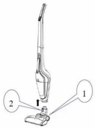
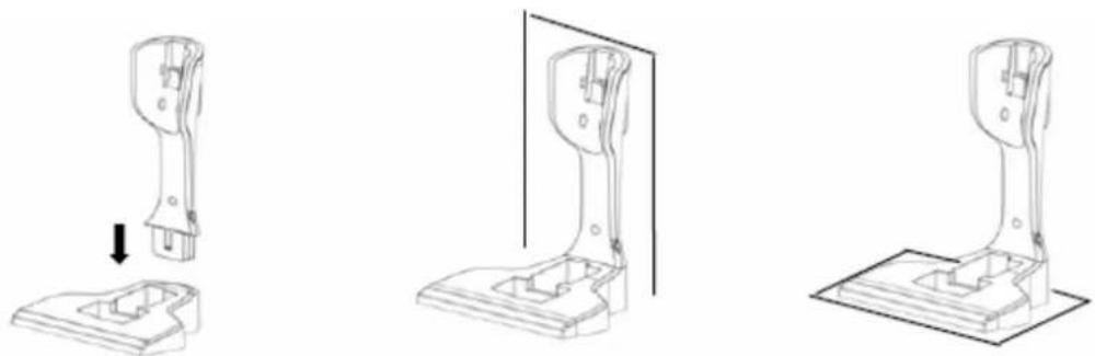
Install the charger and charger stand
Insert the charger into the charger stand, then use the screws attached to fix the whole unit onto the wall or put it on a horizontal surface.
natural_image
Three technical line drawings of a mechanical bracket assembly, showing front, side, and top views with no text or symbols.• OPERATING INSTRUCTIONS
Operate the whole unit
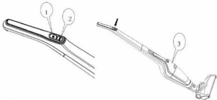
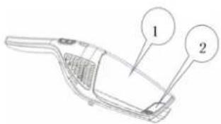
There are two switches, including a power (1) and a speed adjust switch (2).
Press down the power switch (1), the appliance enters working mode and the roll brush starts to work. It is used for cleaning floor and carpet.
○ Press down the speed adjust switch (2), the appliance slows down. Press the speed adjust switch (2) again to return to normal speed.
○ Press the power switch (1) if you want to make the appliance stop working.
During operation, please pay attention to the charging indicators (3). The indicators will go out gradually as the level of charge reduces and the appliance will stop working automatically when all the indicators have gone out.
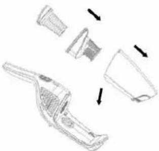
Operating the sub9unit
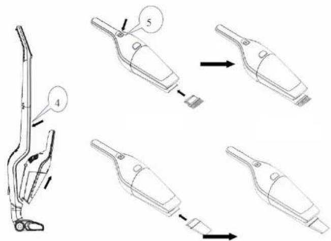
- Press down the sub-unit release button (4), grasp the handle of the sub-unit to remove it by following the arrow shown, and then press down the sub-unit switch (5). The sub-unit enters working mode, and you can press the switch (5) to make it stop working.
If you need to use the dusting brush, please insert it into the suction nozzle of the sub-unit and then activate it again. If you need to use the crevice tool, insert it into the suction nozzle of sub-unit and then activate it again.
• xHàRwINwllINSTRUxTIONSI
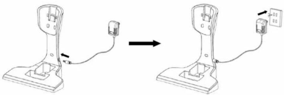
- Fix the charger, insert the small end of the adapter into the charger stand.
- Insert the large end of the adaptor into the power outlet and then connect the power source well.
natural_image
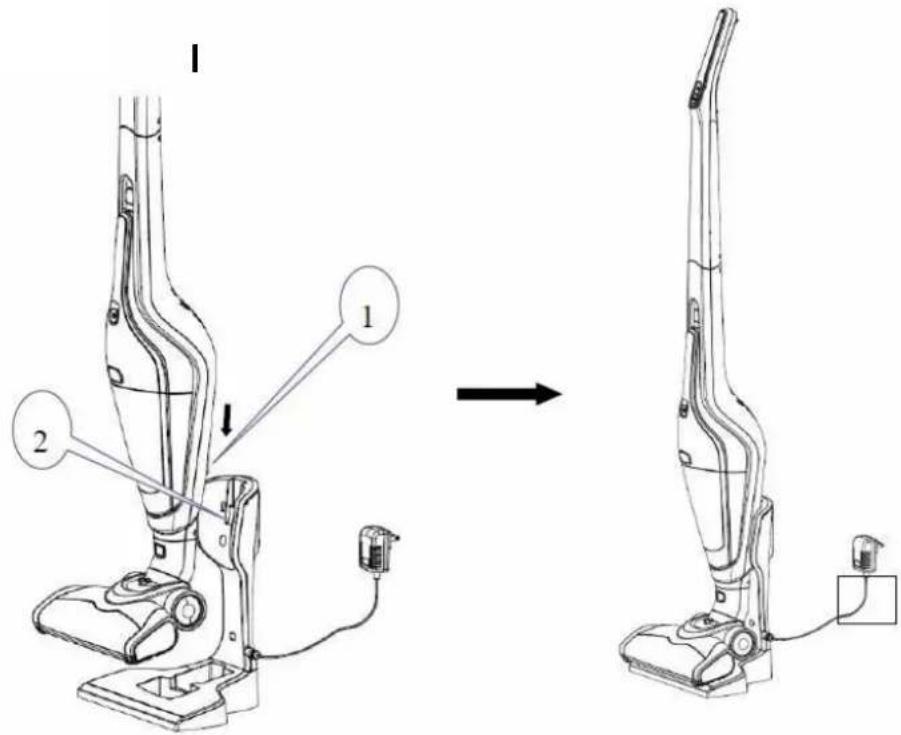
Diagram showing two identical mechanical devices connected by wires, with one device being inserted and the other holding a cable (no text or symbols present)- Lift the appliance and put it onto the charger, ensuring that the socket of the body (1) covers the charger stand (2). At that time, the charging indicator turns on, and the appliance enters charging mode. All the charging indicators will turn on when charging is complete.
NOTE: The appliance cannot be activated during the charging process.
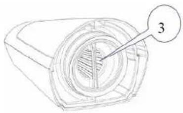
- Detach the accessory from the sub-unit, and then press the release button (2) of the dust cup (1) to separate it from the sub-unit.
- Grasp the filter handle (3) and remove the filter assembly (4) from the dust cup, and then empty the dust cup and rinse it with water. Finally, wipe the residual water from the dust cup.
natural_image
Technical line drawing of a mechanical component with a numbered callout (no text or symbols present)
natural_image
Technical illustration of a mechanical component with a cylindrical part and a flanged base, showing an arrow indicating direction (no text or symbols present)- Grasp the filter handle (3) and rotate it anticlockwise to remove the HEPA filter (5), and then empty the filter cover (6) and rinse it with water. Finally, wipe the residual water from the filter cover.
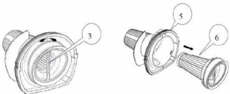
- Clean the HEPA filter (5) with water if the appliance is working inefficiently. Dry it completely after cleaning.
NOTE: HEPA filters and other spare parts can be purchased from the vacuum cleaner retailers.
○ After cleaning the dust cup assembly, please install the HEPA filter into the filter cover first, and then put them into the dust cup. Then, install the dust cup into the sub-unit.
natural_image
Line drawing of a handbag with three views and arrows indicating process (no text or symbols)☐ If hair is found on the floor brush, press the roll brush release tab (7) as shown below to open the roll brush cover, and then remove the roll brush (8).
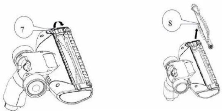
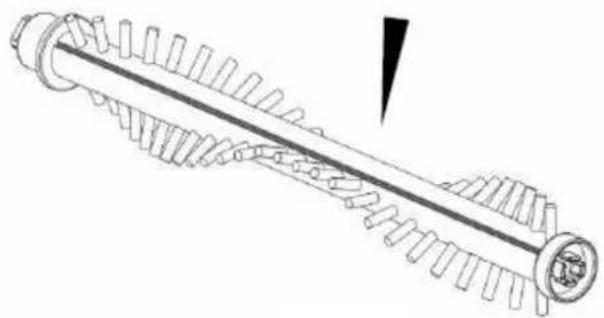
- Score along the locating slot of the roll brush with a blade to cut and remove foreign bodies. Then, install the floor brush securely again and close the roll brush cover.
natural_image
Technical line drawing of a mechanical gear assembly with no visible text or symbolsNOTE: It is advisable to clean the dust cup after every use. If the HEPA filter is blocked by dust accumulation, please clean or replace it in time. The electric roll brush may become wrapped in hair or other fibres after long-term use, so please clean it in time to make the appliance work efficiently.
|
- DISPOSAL
- For proper disposal, please return device to a retailer, a service agent or Rotel AG.
European Directive 2012/19/EC concerning Waste Electrical and Electronic Equipment (WEEE) states that household appliances should not be disposed of using the normal solid urban waste cycle. Exhausted appliances should be collected separately in order to optimise the cost of re-using and recycling materials comprising the machine, while preventing potential damage to public health and the environment. The crossed-out wheeled bin symbol appears on all products to remind owners of the obligations regarding separate waste collection. Owners should contact their local authorities or appliance dealers for further information concerning the correct disposal of household appliances.
This appliance conforms to the following EU directives:
CE
2014/35/EU (Low Voltage Directive) 2014/30/EU (Electromagnetic Compatibility Directive)
D/F/I/E
• GARANTIE / GARANTIE / GARANZIA / WARRANTY
• 2 JAHRE GARANTIE
• 2 ANS DE GARANTIE
• 2 ANNI DI GARANZIA
• 2 YEARS WARRANTY
o Warranty commitment
We commit ourselves to repair this device free of charge, should a failure occur within the period of warranty despite proper handling. We repair all defects caused by material or manufacturing faults. The guarantee will be fulfilled either by repairing the device or replacing the defective parts, according to our judgement. A warranty does not cover damages due to wearing parts, damages and defects caused by improper handling or maintenance (such as limescale and commercial use). It will only be granted if either the warranty card stating date of purchase, dealer's stamp and signature, or the purchase receipt is sent with the device to the relevant after-sales service (see address below). Devices shall be returned in their original packaging. Transport costs are to be borne by the purchaser. Remember to specify your address to your sending, as well as a short declaration about the failure, shall the defect not be obvious.
Servicestation:
Service après-vente: Rotel AG

- • SxHEMATISxHE DARSTELLUNw
- Deutsch yrançais Italiano English
- TECHNISCHE DATEN
- • BETRIEBSANLEITUNw
- - àNLEITUNwIZUMILàqENlqESlwERÄTESI
- • REINIwUNwlUNqlWàRTUNwl
- • INSTRUCTIONS D'UTILISATION
- • INSTRUxTIONSlqElRExHàRwEl
- • ISTRUZIONI D'USO
- • ISTRUZIONIIqIlxàRIxàl
- • PULIZIÀIEIMÀNUTENZIONEI
- • INSTALLATION INSTRUCTIONS
- Install the body and floor brush
- Install the charger and charger stand
- • OPERATING INSTRUCTIONS
- Operate the whole unit
- Operating the sub9unit
- • xHàRwINwllINSTRUxTIONSI
- - DISPOSAL
- • GARANTIE / GARANTIE / GARANZIA / WARRANTY
- o Warranty commitment
- Servicestation:
Brand : ROTEL
Model : U6081CH
Category : Broom