
AC60FS1ERA - Air Conditioning HAIER - Free user manual and instructions
Find the device manual for free AC60FS1ERA HAIER in PDF.
| Brand | Haier |
| Model | AC60FS1ERA |
| Product type | Reversible air conditioning (heating and cooling) cassette ceiling type |
| Refrigerant | R410A, GWP 1975 |
| Power supply | Single-phase 220-230 V ~ 50 Hz (or three-phase 380-400 V 3N~ depending on configuration) |
| Power | 60,000 BTU/h (approx. 17.6 kW) |
| Operating modes | Auto, Cooling, Heating, Dehumidification, Ventilation |
| Special functions | Sleep, Turbo, Quiet, On/Off timer, Healthy air, Airflow direction (vertical) |
| Remote control | Wired or wireless (included), range 7 m, R03 batteries |
| Air filter | Washable, monthly cleaning recommended |
| Automatic defrost | Yes, in heat pump mode, cycle of 7 to 12 minutes |
| Protections | Circuit breaker, differential circuit breaker, magnetic-thermal protection, automatic shutdown in case of failure |
| Installation | Suspended ceiling, requires a certified professional |
| Indoor unit weight | Approx. 30-35 kg (estimate) |
| Indoor unit dimensions (W x D x H) | Approx. 1530 x 640 x 300 mm (estimate from installation dimensions) |
| Operating temperature (cooling) | Indoor: 18-32 °C DB, Outdoor: 10-46 °C DB |
| Operating temperature (heating) | Indoor: 15-27 °C DB, Outdoor: -15-24 °C DB |
| Certifications | CE, RoHS, WEEE, compliant with European directives |
Frequently Asked Questions - AC60FS1ERA HAIER
User questions about AC60FS1ERA HAIER
0 question about this device. Answer the ones you know or ask your own.
Ask a new question about this device
Download the instructions for your Air Conditioning in PDF format for free! Find your manual AC60FS1ERA - HAIER and take your electronic device back in hand. On this page are published all the documents necessary for the use of your device. AC60FS1ERA by HAIER.
USER MANUAL AC60FS1ERA HAIER
text_image
Haier CONVERTIBLE TYPE AIR CONDITIONER OPERATION MANUAL AND INSTALLATION MANUAL
natural_image
Front view of a white air conditioner unit with yellow indicator lights (no text or symbols visible)AC28ES1ERA AC36ES1ERA
natural_image
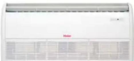
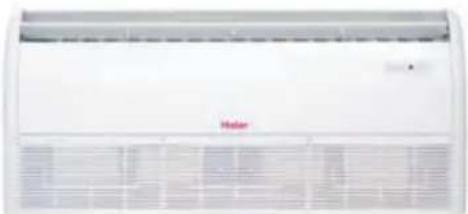
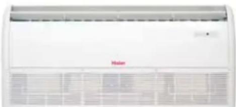
Front view of a white air conditioner unit with ventilation grilles and a red 'Maser' logo (no visible text or symbols on the device itself)AC48FS1ERA AC60FS1ERA

text_image
Haier CONVERTIBLE TYPE AIR CONDITIONER OPERATION MANUAL AND INSTALLATION MANUAL
natural_image
Pure electrical circuit lines without any symbolsAC28ES1ERA AC36ES1ERA
natural_image
Front view of a white air conditioner unit with ventilation grilles and a red 'Mahan' logo (no visible text or symbols on the device itself)AC48FS1ERA AC60FS1ERA
Contents
Cautions 3
Safety Precautions 5
Features and Functions 6
Parts and Functions 8
Operation 10
Maintenance 12
Operation Tips 12
Troubleshooting 13
Installation Procedure 16
Test Run 23
- Please read this manual carefully before installation. Keep this operation manual for future reference.
EUROPEAN REGULATIONS CONFORMITY FOR THE MODELS
CE
All the products are in conformity with the following European provision:
- Low Voltage Directive 73/23/EEC
- Low Voltage Directive 2006/95/EC
-Electomagnetic CompatibilitY 89/336/EEC
-Electomagnetic Compatibility 2004/108/EC
ROHS
The products are fulfilled with the requirements in the directive 2002/95/EEC of the European parliament and of council on the Restriction of the use of Certain Hazardous Substances in Electrical and Electronic Equipment (EU RoHS Directive)
WEEE
In accordance with the directive 2002/96/CE of the European parliament, herewith we inform the consumer about the disposal requirements of the electrical and electronic products.
DISPOSAL REQUIREMENTS:
Your air conditioning product is marked with this symbol. This means that electrical and electronic products shall not be mixed with unsorted household waste. Do not try to dismantle the system yourself: the dismantling of the air conditioning system, treatment of the refrigerant, of oil and of other part must be done by a qualified installer in accordance with relevant local and national legislation. Air conditioners must be treated at a specialized treatment facility for reuse, recycling and recovery. By ensuring this product is disposed of correctly, you will help to prevent potential negative consequences for the environment and human health. Please contact the installer or local authority for more information. Battery must be removed from the remote controller and disposed of separately in accordance with relevant local and national legislation.
IMPORTANT INFORMATION REGA- RDING THE REFRIGERANT USED
text_image
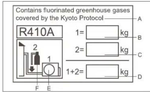
Contains fluorinated greenhouse gases covered by the Kyoto Protocol R410A 1= kg 2= kg 1+2= kg A B C D F EThis product contains fluorinated greenhouse gases covered by the Kyoto Protocol. Do not vent into the atmosphere.
Refrigerant type:R410A
GWP* value:1975
GWP=global warming potential
Please fill in with indelible ink,
• 1 the factory refrigerant charge of the product
• 2 the additional refrigerant amount charged in the field and
• 1+2 the total refrigerant charge
on the refrigerant charge label supplied with the product. The filled out label must be adhered in the proximity of the product charging port (e.g. onto the inside of the stop value cover).
A contains fluorinated greenhouse gases covered by the Kyoto Protocol
B factory refrigerant charge of the product: see unit name plate
C additional refrigerant amount charged in the field
D total refrigerant charge
E outdoor unit
F refrigerant cylinder and manifold for charging
Disposal of the old air conditioner
Before disposing an old air conditioner that goes out of use, please make sure it's inoperative and safe. Unplug the air conditioner in order to avoid the risk of child entrapment.
It must be noticed that air conditioner system contains refrigerants, which require specialized waste disposal. The valuable materials contained in a air conditioner can be recycled. Contact your local waste disposal center for proper disposal of an old air conditioner and contact your local authority or your dealer if you have any question. Please ensure that the pipework of your air conditioner does not get damaged prior to being picked up by the relevant waste disposal center, and contribute to environmental awareness by insisting on an appropriate, anti-pollution method of disposal.
Disposal of the packaging of your new air conditioner
All the packaging materials employed in the package of your new air conditioner may be disposed without any danger to the environment.
The cardboard box may be broken or cut into smaller pieces and given to a waste paper disposal service. The wrapping bag made of polyethylene and the polyethylene foam pads contain no fluorochloric hydrocarbon.
All these valuable materials may be taken to a waste collecting center and used again after adequate recycling.
Consult your local authorities for the name and address of the waste materials collecting centers and waste paper disposal services nearest to your house.
Safety Instructions and Warnings
Before starting the air conditioner, read the information given in the User's Guide carefully. The User's Guide contains very important observations relating to the assembly, operation and maintenance of the air conditioner.
The manufacturer does not accept responsibility for any damages that may arise due to non-observation of the following instruction.
- Damaged air conditioners are not to be put into operation. In case of doubt, consult your supplier.
- Use of the air conditioner is to be carried out in strict compliance with the relative instructions set forth in the User's Guide.
• Installation shall be done by professional people. Don't install unit by yourself.
- For the purpose of safety, the air conditioner must be properly grounded in accordance with specifications.
• Always remember to unplug the air conditioner before opening inlet grill. Always grip plug firmly and pull straight out from the outlet.
- All electrical repairs must be carried out by qualified electricians. Inadequate repairs may result in a major source of danger for the user of the air conditioner.
- Do not damage any parts of the air conditioner that carry refrigerant by piercing or perforating the air conditioner's tubes with sharp or pointed items, crushing or twisting any tubes, or scraping the coatings off the surfaces. If the refrigerant spurts out and gets into eyes, it may result in serious eye injuries.
- Do not obstruct or cover the ventilation grille of the air conditioner. Do not put fingers or any other things into the inlet/outlet and swing louver.
- Do not allow children to play with the air conditioner. In no case should children be allowed to sit on the outdoor unit.
- When the indoor unit is turned on, the PCB will test if swing motor is O.K., and then fan motor will start up. So there is a few seconds to wait.
- In cooling mode, the flaps will swing automatically to a fixed position for anti-condensating.
- This appliance is not intended for use by persons (including children) with reduced physical, sensory or mental capabilities, or lack of experience and knowledge, unless they have been given supervision or instruction concerning use of the appliance by a person responsible for their safety.
- Children should be supervised to ensure that they do not play with the appliance.
Specifications
• The refrigerating circuit is leak-proof.
- For all the models in this manual, the all-pole discon-nexion connection method should be applied in the power supply. Such means for disconnection must be incorporation in the fixed wiring.
Temperature and Humidity Range
| Cooling | Indoor temperature | max. DB/WBmin. DB/WB | 32/23°C18/14°C |
| Outdoor temperature | max. DB/WBmin. DB/WB | 46/26°C10/6°C | |
| Heating | Indoor temperature | max. DB/WBmin. DB/WB | 27°C15°C |
| Outdoor temperature | max. DB/WBmin. DB/WB | 24/18°C-15°C |
- If the air conditioner is used under higher temperature condition than those listed, the built-in protection circuit may operate to prevent internal circuit damage. Also, during Cooling and Dry modes, if the unit is used under conditions of lower temperature than those listed above, the heat-exchanger may freeze, leading to water leakage and other damage.
- Do not use this unit for purposes other than cooling, heating, dehumidifying and ventilation of rooms in ordinary dwellings.
- The wiring method should be in line with the local wiring standard.
- The waste battery should be disposed properly.
- If the fuse on PC board is broken, please change it with the type T 3.15A/250VAC.
WARNING
- The breaker of the air conditioner should be all-pole switch, and the distance between its two contacts should be no less 3mm . Such means for disconnection must be incorporation in the fixed wiring.
- Use copper wire only. All the cables shall have got the European authentication certificate.
- The power supply connects from the outdoor side. The connecting cable and the power cable are self-provided.
- The parameter of connecting cable: H05RN-F 4G 0.75mm^2 .
DANGER
- Do not attempt to install this air conditioner by yourself.
- This unit contains no user-serviceable parts. Always consult authorized service personnel for repairs.
- When moving, consult authorized service personnel for disconnection and installation of the unit.
- Do not become excessively chilled by staying for lengthy periods in the direct cooling airflow.
- Do not insert fingers or objects into the outlet port or intake grills.
- Do not start and stop air conditioner operation by connecting and disconnecting the power supply cord and so on.
- Take care not to damage the power supply cord. If the supply cord is damaged, it must be replaced by the manufacturer or authorised service agent in order to avoid a hazard.
- In the event of a malfunction (burning smell, etc.), stop operation immediately, turn off the circuit breaker, and consult authorized service personnel.
WARNING
- Provide occasional ventilation during use.
- Do not direct air flow at fire places or heating apparatuses.
- Do not place objects on the air conditioner or climb onto it.
- Do not hang objects from the indoor unit.
- Do not set flower vases or water containers on top of the air conditioner.
- Do not expose the air conditioner directly to water.
- Do not operate the air conditioner with wet hands.
- Do not pull power supply cord.
- Turn off power source when not using the unit for extended periods.
- Check the condition of the installation stand for damage.
- Do not place animals or plants in the direct path of the air flow.
- Do not drink the water drained from the air conditioner.
- Do not use in applications involving the storage of foods, plants or animals, precision equipment or art works.
- Do not apply any heavy pressure to radiator fins.
- Operate only with air filters installed.
- Do not block or cover the intake grill and outlet port.
- Ensure that any electronic equipment is at least one metre away from either the indoor or outdoor unit.
- Avoid installing the air conditioner near a fireplace or other heating apparatuses.
- When installing the indoor and outdoor unit, take precautions to prevent access to infants.
- Do not use inflammable gases near the air conditioner.
AUTOMATIC OPERATION
• COOLING TYPE
Merely press the ON/OFF button, and the unit will begin automatic operation in the Cooling or dry modes as appropriate, in accordance with the thermostat setting and the actual temperature of the room.
•HEAT & COOL TYPE
Merely press the ON/OFF button, and the unit will begin automatic operation in any of the Heating, Cooling and Blow modes as appropriate, in accordance with the thermostat setting and the actual temperature of the room.
SLEEP
• COOLING TYPE
When the SLEEP button is pressed during Cooling or Dry mode, the thermostat setting gradually rises during the period of operation. When the set time is reached, the unit automatically turns off.
•HEAT & COOL TYPE
When the SLEEP button is pressed during Heating mode, the air conditioner's thermostat setting gradually lowers during the period of operation; When the set time is reached, the unit automatically turns off.
WIRELESS REMOTE CONTROL UNIT
- The WIRELESS REMOTE CONTROL UNIT allows convenient control of air conditioner operation. For this type unit, the wireless remote controller type is YR-H50.
MILDEW-RESISTANT FILTER
• The AIR FILTER has been treated to resist mildew growth, thus allowing cleaner use and easier care.
VERTICAL AIR DIRECTION ADJUSTMENT
Press the AIR FLOW DIRECTION VERTICAL SET button.
• Each time the button is pressed, the air direction range will change as follows:
Cool/Dehumidification/Fan:
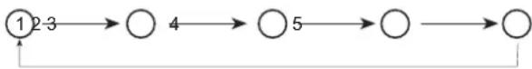
flowchart
graph LR
    A["1"] --> B["2-3"]
    B --> C["○"]
    C --> D["4"]
    D --> E["○5"]
    E --> F["○"]
    F --> G[" "]
    G --> H[" "]
Heat:
flowchart
graph LR
    A["5"] --> B["4"]
    B --> C["3"]
    C --> D["2"]
    D --> E["1"]
    E --> F["0"]
    F --> G["0"]
    G --> H["1"]
text_image
Technical diagram of a mechanical component with numbered parts and directional arrows indicating flow or movement.- Use the air direction adjustment within the ranges shown above.
- The vertical airflow direction is set automatically as shown, in accordance with the type of operation selected.
Features and Functions
HORIZONTAL AIR DIRECTION ADJUSTMENT
Press the AIR FLOW DIRECTION HORIZONTAL SET button.
• Each time the button is pressed, the air direction range will change as follows:
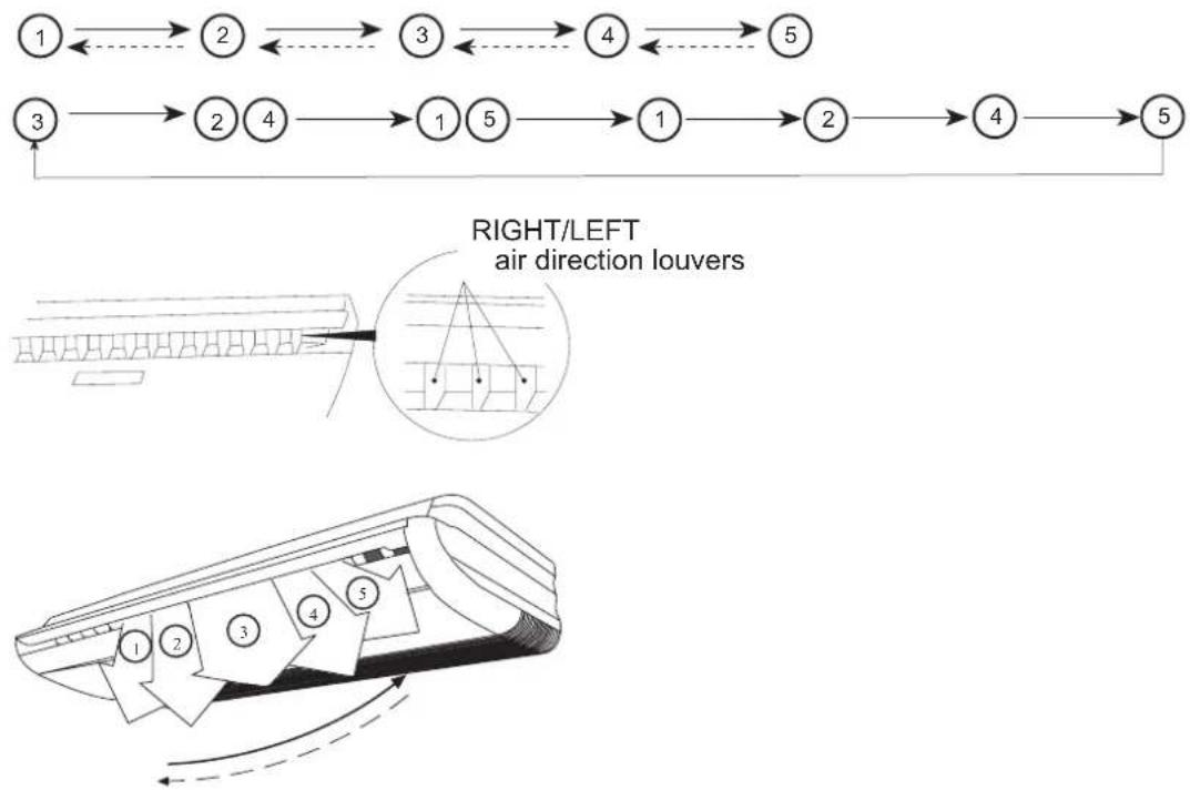
flowchart
graph TD
    A["1"] --> B["2"]
    B --> C["3"]
    C --> D["4"]
    D --> E["5"]
    F["3"] --> G["2"]
    G --> H["4"]
    H --> I["1"]
    I --> J["5"]
    J --> K["1"]
    K --> L["2"]
    L --> M["4"]
    M --> N["5"]
- Use the air direction adjustments within the ranges shown above.
• The swing range of up-down flap is as follow :
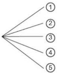
flowchart
graph TD
    A[" "] --> B["1"]
    A --> C["2"]
    A --> D["3"]
    A --> E["4"]
    A --> F["5"]
| Air flow direction set Range of swing | |
| 1 | 1 to 3 |
| 2 | 1 to 3 |
| 3 | 2 to 4 |
| 4 | 3 to 5 |
| 5 | 1 to 5 (all range) |
Note :
When being switched on firstly, the up-down flap will be at the position of max. angle. In cooling, the up-down louver is not good to stay at position 4, 5 for a long time, otherwise, the dew will occur.
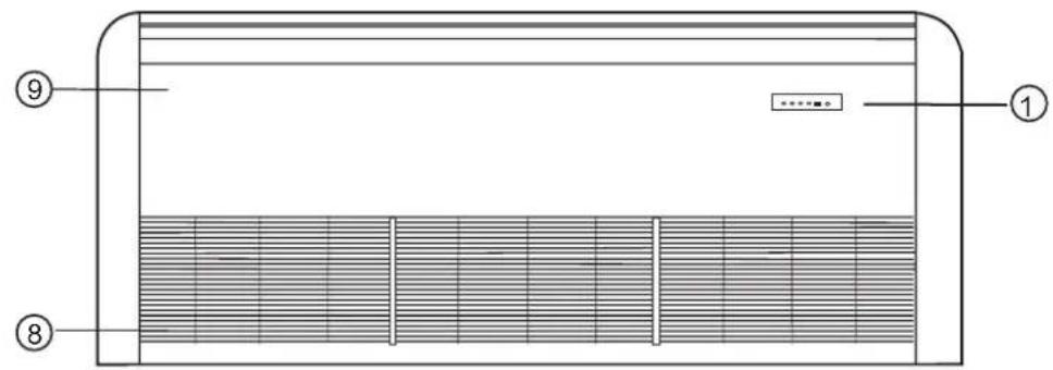
Indoor unit
text_image
Technical diagram of a ventilation system with numbered components and internal structure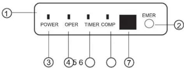
text_image
POWER OPER TIMER COMP EMER ① ② ③ ④ ⑤ ⑥ ⑦(1) Operating Control Panel
(2) Emergency Switch
(3) Power Indicator Lamp
(4) OPERATION Indicator Lamp
(5) TIMER Indicator Lamp
(6) Compressor Lamp
(7) Remote Receiver
(8) Inlet Grill (Filter inside)
(9) Front Panel
Note :
For the wired control type unit, the unit state should be checked by the wired controller, instead of the remote receiver. And if you set the TIMER function, the TIMER LED on the remote receiver will not be on.
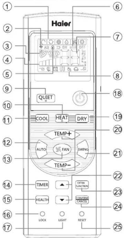
Remote controller
text_image
Haier QUIET COOL HEAT DRY TEMP+ AUTO FAN SWING TEMP- TIMER EXTRA FUNCTION HEALTH CONFIRM CANCEL LOCK LIGHT RESET- Loading of the battery
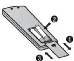
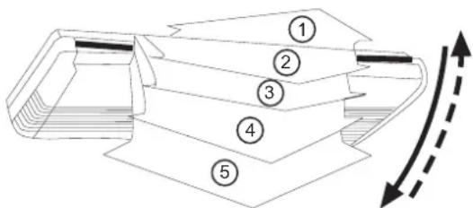
text_image
Diagram of a battery pack with labeled components and directional arrows indicating movement or force1 Remove the battery cover; 2 Load the batteries as illustrated. 2 R-03 batteries, resetting key (cylinder);
3 Be sure that the loading is in line with the " + "/"-";
4 Load the battery, then put on the cover again.
Note:
● The distance between the signal transmission head and the receiver hole should be within 7m without any obstacle as well.
- When electronic-started type fluorescent lamp or change-over type fluorescent lamp or wireless telephone is installed in the room, the receiver is apt to be disturbed in receiving the signals, so the distance to the indoor unit should be shorter.
● Full display or unclear display during operation indicates the
batteries have been used up. Please change batteries.
- If the remote controller can't run normally during operation, please remove the batteries and reload several minutes later.
Hint:
Remove the batteries in case won't be in use for a long period. If there is any display after taking-out, just press reset key.
1. Mode display
| Operation mode | AUTO | COOL | DRY | HEAT | FAN |
| Remote controller |
- Signal sending display
- SWING display
- FAN SPEED display
- LOCK display
- TIMER OFF display
TIMER ON display
7.TEMP display
- Additional functions display
| Operation mode | QUITE | SLEEP | Supplemented electrical heating | HEALTH | POWER |
| Remote controller |
Electrical heating is not available.
-
QUIET button
-
HEAT button
-
COOL button
-
AUTO button
-
FAN button
-
TIMER button
-
HEALTH button
(This model has not this function.)
- LOCK button
Used to lock buttons and LCD display
- LIGHT button
(This model has not this function.)
Control the lightening and extinguishing
of the indoor LED display board.
-
POWER ON/OFF button
-
DRY button
-
TEMP button
-
SWING button
-
HOUR button
-
EXTRA FUNCTION button
Function: Fan only function, health airflow
upwards and downwards sending
function,sleep function,
air-refresh(reserved function)
Fahrenheit Celsius conversion
Power setting function
left and right swing function,10°C heating function
24.CANCEL/CONFIRM button
Function: Setting and cancel to the
timer and other additional functions.
- RESET button
When the remote controller
appears abnormal, use a sharp
pointed article to press this button
to reset the remote
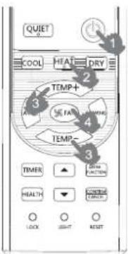
Base Operation
Remote controller
text_image
QUIET COOL HEAT DRY TEMP+ TEMP- TEMP- TIMER ▲ HEALTH ▼ CONTROL LOCK SHIFT RESET- Unit start
Press ON/OFF on the remote controller, unit starts.
- Select operation mode
COOL button:Cooling mode
HEAT button: Heating mode
DRY button: Dehumidify mode
- Select temp. setting
Press TEMP+ / TEMP- button
TEMP+ Every time the button is pressed, temp. setting increase 1°C, if kept depressed, it will increase rapidly
TEMP— Every time the button is pressed, temp. setting decrease 1°C, if kept depressed, it will decrease rapidly
Select a desired temperature.
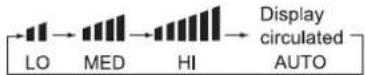
- Fan speed selection
Press FAN button. For each press, fan speed changes as follows:
Remote controller:
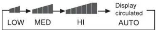
flowchart
graph LR
    A["LOW"] --> B["MED"]
    B --> C["HI"]
    C --> D["Display circulated AUTO"]
Air conditioner is running under displayed fan speed. When FAN is set to AUTO, the air conditioner automatically adjusts the fan speed according to room temperature.
| Operation Mode | Remote Controller | Note |
| AUTO |  | Under the mode of auto operation, air conditioner will automatically select Cool or Heat operation according to room temperature. When FAN is set to AUTO the air conditioner automatically adjusts the fan speed according to room temperature. |
| COOL |  | |
| DRY |  | In DRY mode, when room temperature becomes lower than temp. setting+2°C, unit will run intermittently at LOW speed regardless of FAN setting. |
| HEAT |  | In HEAT mode, warm air will blow out after a short period of the time due to cold-draft prevention function. When FAN is set to AUTO, the air conditioner automatically adjusts the fan speed according to room temperature. |
| FAN |  | In FAN operation mode, the unit will not operate in COOL or HEAT mode but only in FAN mode, AUTO is not available in FAN mode. And temp. setting is disabled. In FAN mode, sleep operation is not available. |
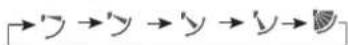
Sleep Operation
Press EXTRA FUNCTION button to enter additional options, when cycle display to 📋, 📋 will flash. And then press CONTRM CANCEL enter to sleep function.

natural_image
Close-up of a person sleeping on a bed with soft white bedding (no text or symbols visible)Operation Mode
- In COOL, DRY mode
1 hours after SLEEP mode starts, temp. will become 1^ C higher than temp. setting. After another 1 hours, temp. rises by 1^ C further. The unit will run for further 6 hours then stops Temp. is higher than temp. setting so that room temperature won't be too low for your sleep.
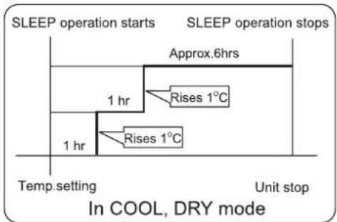
flowchart
graph TD
    A["SLEEP operation starts"] --> B["Approx.6hrs"]
    B --> C["1 hr"]
    C --> D["Rises 1°C"]
    D --> E["1 hr"]
    E --> F["Rises 1°C"]
    F --> G["Temp. setting"]
    G --> H["Unit stop"]
    style A fill:#f9f,stroke:#333
    style B fill:#ccf,stroke:#333
    style C fill:#cfc,stroke:#333
    style D fill:#fcc,stroke:#333
    style E fill:#cff,stroke:#333
    style F fill:#ffc,stroke:#333
    style G fill:#f9f,stroke:#333
    style H fill:#ccf,stroke:#333
- In HEAT mode
1 hours after SLEEP mode starts, temp will become 2^ C lower than temp. setting. After another 1 hours, temp decrease by 2^ C further. After more another 3 hours, temp. rises by 1^ C further. The unit will run for further 3 hours then stops. Temp. is lower than temp. setting so that room temperature won't be too high for your sleep.
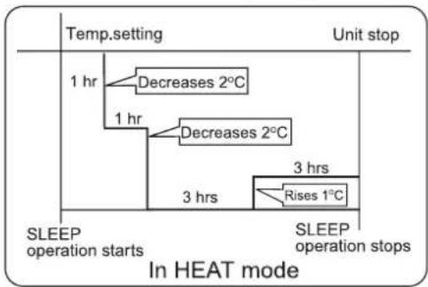
flowchart
graph TD
    A["Temp. setting"] --> B["1 hr"]
    B --> C["Decreases 2°C"]
    B --> D["1 hr"]
    D --> E["Decreases 2°C"]
    D --> F["3 hrs"]
    F --> G["Rises 1°C"]
    G --> H["SLEEP operation stops"]
    style A fill:#f9f,stroke:#333
    style H fill:#ccf,stroke:#333
- In AUTO mode
The unit operators in corresponding sleep mode adapted to the automatically selected operation mode.
Operation
4. In FAN mode
It has no SLEEP function.
- Set the wind speed change when sleeping If the wind speed is high or middle before setting for the sleep, set for lowing the wind speed after sleeping. If it is low wind, no change.
Note
When TIMER function is set, the sleeping function can't be set up. After the sleeping function is set up, if user resets TIMER function, the sleeping function will be cancelled; the machine will be in the state of timing-on.
POWER/QUIET Operation
(1) POWER Operation
When you need rapid heating or cooling, you can use this function.
Press EXTRA FUNCTION button to enter additional options, when cycle display to 📋, 📋 will flash, and then press CONFIRM CANCEL, enter to power function. When cancel the function, please enter additional options again and to cancel power function.
(2) QUIET Operation
You can use this function when silence is needed for rest or reading.
Press QUIET button, the remote controller will show 🔗, and then achieve to the quiet function. Press again this QUIET button, the quiet function will be cancelled.
Note :
During POWER operation, in rapid HEAT or COOL mode, the room will show inhomogeneous temperature distribution. Long period QUIET operation will cause effect of not too cool or not too warm.
Air Flow Direction Adjustment
1. Status display of air flow
COOL/DRY:
HEAT:

Initial state
2. Left and right air flow adjustment
(available only for convertible unit)
Press button EXTRA FUNCTION to select auxiliary function, the LCD will display in cycle, press CONFIRM CANCEL to confirm. Enter left and right air flow adjustment, please press button SWING to adjust the air flow angle.

Note: 7.20 both of the two positions are null.
Timer On/Off On-Off Operation
- After unit starts, select your desired operation mode.
- Press TIMER button to change TIMER mode. Every time the button is pressed, display changes as follows: Remote controller:
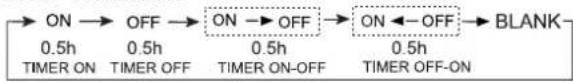
flowchart
graph LR
    A["ON"] --> B["OFF"]
    B --> C["ON → OFF"]
    C --> D["ON ← OFF"]
    D --> E["BLANK"]
    F["0.5h TIMER ON"] --> G["0.5h TIMER OFF"]
    H["0.5h TIMER ON-OFF"] --> I["0.5h TIMER OFF-ON"]
Then select your desired TIMER mode (TIMER ON or TIMER OFF or TIMER ON-OFF). "ON "or "OFF" will flash.
- Press ▼ / ▲ button to set time.
▲ Press the button for each time, setting time in the first 12 hours increased by 0.5 hour every time, after 12 hours, increased by 1 hour every time.
▼ Press the button for each time, settling time in the first 12 hours decreased by 0.5 hour every time, after 12 hours, decreased by 1 hour every time. It can be adjusted within 24 hours.
- Confirm timer setting
After adjust the time, press CONFIRM CANCEL button and confirm the time ON or OFF button will not flash any more.
- Cancel timer setting
Press the timer button by times until the time display eliminated.
Hints:
After replacing batteries or a power failure happens, time setting should be reset.
According to the Time setting sequence of TIMER ON or TIMER OFF, either Start-Stop or Stop-Start can be achieved.
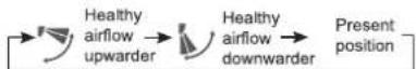
■ Healthy airflow Operation
- Press ⏻ to starting
Setting the comfort work conditions.
- The setting of healthy airflow function
Press EXTRA FUNCTION button to enter additional options, Press this button continuously, the louvers location will cycle between in the following three locations, to choose the swing location what you needed, and then press CONFIRM CANCEL button to confirm.
- The cancel of the healthy airflow function
Press EXTRA FUNCTION button to enter additional options, Press this button continuously, the louvers location will cycle between in the following three locations again, and then press button to cancel.
Notice: Do not direct the flap by hand. Otherwise, the grille will run incorrectly. If the grille is not run correctly, stop for a minute and then start, adjusting by remote controller.
Note:
-
After setting the healthy airflow function, the position grill is fixed.
-
In heating, it is better to select the mode.
-
In cooling, it is better to select the mode.
-
In cooling and dry, using the air conditioner for a long time under the high air humidity, condensate water may occur at the grille.
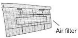
Maintenance
Clean the air filter
- Pull the filters upward to remove them from the Intake Grill.
- Clean the air filter: Remove the dust from the filters by vacuum cleaner or washing them. After washing, allow the air filters to dry thoroughly in an area protected from sunlight.
- Re-attach the air filters to the Intake Grill. Press the two buttons on the filters until you hear a sound of click.
natural_image
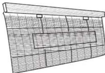
Architectural or engineering diagram showing a grid-patterned structure with no visible text, numbers, or symbols.Maintenance of indoor units
- When used for extended periods, the unit may accumulate dirt inside, which reduces its performance. We recommend that the unit is inspected regularly, in addition to your own cleaning and care. For more information, consult authorized service personnel.
- When cleaning the unit's body, do not use water hotter than 40^ , harsh abrasive cleansers, or volatile agents like benzene or thinner.
- Do not expose the unit body to liquid insecticides or hairsprays.
- When shutting down the unit for one month or more, first allow the Fan mode to operate continuously for about half a day to allow internal parts to dry thoroughly.
Operation tips
Instructions relating to heating are applicable only to "HEAT & COOL TYPE"
Heating Performance
- This air conditioner operates on the heat-pump principle, absorbing heat from outdoor air and transferring that heat indoors. As a result, the operating performance is reduced as outdoor air temperature drops. If you feel that insufficient heating performance is being produced, we recommend you use this air conditioner in conjunction with another kind of heating appliance.
- Heat-pump air conditioners heat your entire room by recirculating air throughout the room, with the result that some time may be required after first starting the air conditioner until the room is heated.
Microcomputer-controlled Automatic Defrosting
- When using the Heating mode under conditions of low outdoor air temperature high humidity, frost may form on the outdoor unit, resulting in reduced operating performance.
- In order to prevent this kind of reduced performance, this unit is equipped with a Microcomputer-controlled Automatic Defrosting function. If frost forms, the air conditioner will temporarily stop, and the defrosting circuit will operate briefly (for about 7 to 15 minutes).
Followings are not problems
Sound of water flowing is not a proble | During unit operation or at stop, a swishing or gurgling noise may be heard.This noise is generated by refrigerant flowing in the system. | |
| Sound of cracking is heard. | During unit operation, a cracking noise may be heard.This noise is generated by the casing expanding or shrinking because of temperature changes. | |
| Smell are generated. | This is because the system circulates smells from the interior air such as the smell of cigarettes or the painting on the furniture. | |
| During operation, white fog or steam comes out from the indoor unit. | When unit is running at places like restaurant, etc. where dense edible oil fumes always exist, this will happen. | |
| In cooling operation, unit switches to blowing operation. | To prevent frost from accumulating on indoor heat exchanger, unit will switch to blowing operation for a while then resume cooling operation. | |
| Unit will not restart after stop.Won't start? |  | Though ON/OFF button is set to ON, the unit won't resume cooling, dry or heating operation in 3 min after it is stopped, this is because of 3-min-delay protection circuit. Please wait 3 minutes  |
| No outlet air or fan speed can't be changed in dry mode. | Unit will reduce fan speed repeatedly and automatically if room temp. is too low in dry operation. | |
In heating operation, water or steam are blown out of outdoor unit.  | This occurs when frost accumulated on the outdoor unit is removed.(during defrosting operation) [6x8C] | |
| In heating operation, indoor fan won't stop even if unit is stopped. | After unit stop, indoor fan will go on running until indoor unit cools down. | |
Troubleshooting
Before ask for services, please first check your unit against the following.
| Air conditioner won't start. | ||
Is power supply switch turned on? Power supply switch is not set at ON. Power supply switch is not set at ON. | Is city power supply normal? Is leakage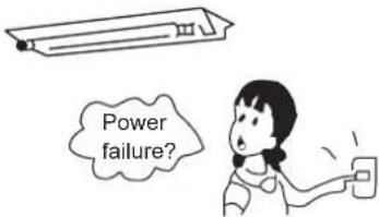 | current breaker activated?This is very dangerous, please disconnect power supply immediately and contact your dealer. |
| Poor cooling or heating | ||
Are operation control adjusted correctly as specified?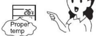 | Is air filter too dirty? Are there any obstacles in inlet or outlet grill?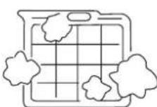 | 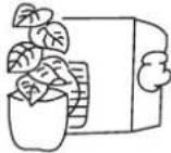 |
| Are horizontal louvers at up position (in heating mode)? | Any doors or windows left open?[IMAGE] | |
| Poor cooling | ||
Is there any direct sunlight in the room? If there are unexpected heat sources in the room?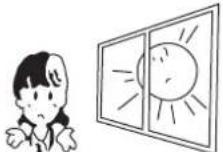 | If there are unexpected heat sources in the room? | Too many people in the room? |
| Cold air blows out (in heating mode). Is air conditioner in standby condition in heating mode? | ||
If your unit still can't work properly after above mentioned checks, or following problems occur, please stop it immediately and contact your dealer.
- Fuses or circuit breakers often blow out.
• Water comes out in cooling/dry operation.
• Operation is abnormal or sound is heard.
When failure happens, the fan of indoor unit stop running. The method of check failure code as follow.
For outdoor failure, the failure code is outdoor failure LED flash times + 20.
For example, the failure code of outdoor unit is 2. the wired controller of indoor unit will display 16(using hexadecimal method).
Ta: ambient temperature sensor
Tm: coil temperature sensor
| Failure code(from receive board) | Failure code(from wired controller) | Failure code(from panel controller) | Trouble shooting | Possible reasons | |
| Flash times of Timing LED(or indoor PCB LED4) | Flash times of Running LED(or indoor PCB LED3) | ||||
| 0 | 1 | 01 | E1 | Temperature sensor Ta faulty | Sensor disconected,or broken,or at wrong position,or short circuit |
| 0 | 2 | 02 | E2 | Temperature sensor Te faulty | Sensor disconected,or broken,or at wrong position,or short circuit |
| 0 4 04 F8 EEPROM WRONG Faulty indoor unit PCB | |||||
| 0 | 7 | 0 | 7 | E between indoor and outdoor units | Wrong connection,or the Abnormal disconected,or wrong address setting of indoor unit,or faulty power supply or faulty PCB |
| 0 | 8 | NO EEROR CODE DISPLAY | E8 Abnormal | al communication between indoor wired controller and indoor unit PCB | Abnormal communication between indoor wired controller and indoor unit PCB |
| 0 | 12 | 0C | E0 | Drainage system abnormal | Pump motor disconnected,or at wrong position,or the float switch broken down,or the float switch disconected,or at wrong position. |
| 0 | 13 | OD | EF | Zero cross signal wrong | Zero cross signal detected wrong |
| 0 | 16 | 10 | F3 | Indoor mode abnormal | Different from outdoor unit mode |
| 2 1 15 / | Outdoor unit abnormal | Refer to the outdoor unit trouble shooting list | |||
| 2 2 16 / | Outdoor unit abnormal | ||||
| 2 4 18 / | Outdoor unit abnormal | ||||
| 2 5 19 / | Outdoor unit abnormal | ||||
| 2 | 7 | 1B | / | Outdoor unit abnormal | |
| 2 | 8 | 1C | / | Outdoor unit abnormal | |
| 2 | 9 | 1D | / | Outdoor unit abnormal | |
| 3 | 0 | 1E | / | Outdoor unit abnormal | |
| 3 | 1 | 1F | / | Outdoor unit abnormal | |
| 3 2 20 / | Outdoor unit abnormal | ||||
| 3 3 21 / | Outdoor unit abnormal | ||||
| 3 5 23 / | Outdoor unit abnormal | ||||
| 3 6 24 / | Outdoor unit abnormal | ||||
| 3 7 25 / | Outdoor unit abnormal | ||||
| 3 8 26 / | Outdoor unit abnormal | ||||
| 3 9 27 / | Outdoor unit abnormal | ||||
| 4 | 3 | 2B | / | Outdoor unit abnormal | |
| 4 | 4 | 2C | / | Outdoor unit abnormal | |
| 4 | 7 | 2F | / | Outdoor unit abnormal | |
| 4 8 30 / | Outdoor unit abnormal | ||||
| 4 9 31 / | Outdoor unit abnormal | ||||
| 5 | 8 | 3A | / | Outdoor unit abnormal | |
| 5 | 9 | 3B | / | Outdoor unit abnormal | |
| 6 | 3 | 3F | / | Outdoor unit abnormal | |
| 6 4 40 / | Outdoor unit abnormal | ||||
- For the indoor failure, only running LED ON remote receiver will indicate.
- For the outdoor failure, timer LED and running LED will indicate. timer LED of remote receiver stands for ten's place, and running LED stands for one's place. timer LED will flash firstly, 2 seconds later, running LED will flash too. After that, 4 seconds later, they will flash in turns again. Flash times equals to the failure code of outdoor plus.
- For example, failure code of outdoor is 2, the indoor unit should display 22. As a result, timer LED flashes twice firstly, then running LED flashes twice.
- To get much more details of outdoor unit failure, Please refer to the outdoor unit trouble shooting list.
nunic
Please ask the dealer or specialist to install, never try by the users themselves. After the installation please be sure of the following conditions.
WARNING
- Please call dealer to install the air-conditioner. Incorrect installation may cause water leaking, shock and fire hazard.
CAUTION
- Air-conditioner can't be installed in the environment with inflammable gases because the inflammable gases near air-conditioner may cause fire hazard.
- Installed electrical-leaking circuit breaker.
It easily cause electrical shock without circuit breaker.
- Connect earthing wire.
Earthing wire should not be connected to the gas pipe, water pipe, lightning rod or phone line, incorrect earthing may cause shock.

- Use discharge pipe correctly to ensure efficient discharge.
Incorrect pipe use may cause water leaking.
• Wiring
Air-conditioner should be equipped with special power supply wire.
- Location
• Air-conditioner should be located in well-vented and easily accessible place.
• Air-conditioner should not be located in the following places:
(1) Places with machine oils or other oil vapours.
(2) Seaside with high salt content in the air.
(3) Near hot spring with high content of sulfide gases.
(4) Area with frequent fluctuation of voltage e.g. factory, etc.
(5) In vehicles or ships.
(6) Kitchen with heavy oil vapour or humidity.
(7) Near the machine emitting electric-magnetic waves.
(8) Places with acid, alkali vapour.
- Choose the following locations:
(1) Capable of supporting air conditioner weight. Don't increase operating noise and vibration.
(2) Hot vapour from outdoor unit outlet and operating noise don't disturb neighbour.
(3) No obstacles around the outdoor unit outlet.
- TV, radio, acoustic appliances etc. are at least 1 m far away from the indoor unit, outdoor unit, power supply wire, connecting wire, pipes, otherwise images may be disturbed or noises be created.
- As required, take measures against heavy snow.
For authorized sevice personnel only
WARNING
(1) For the room air conditioner to operate satisfactorily, install it as outlined in this installation manual.
(2) Connect the indoor unit and outdoor unit with the room air conditioner piping and cords available from our standard parts. This installation manual describes for the correct connections so that the installation set available from our standard parts should be used.
(3) Installation work must be performed in accordance with national wiring standards by authorized personnel only.
(4) Never cut the power cord, lengthen or shorten the cord, or change the plug. Do not use an extension cord.
(5) Plug in the power cord plug firmly. If the receptacle is loose, repair it before using the room air conditioner.
(6) Do not turn on the power until all installation work is done.
CAUTION
(1) Be careful not to scratch the room air conditioner when handing it.
(2) After installation, explain correct operation to the customer, according to the operating manual.
(3) Let the customer keep this installation manual because it will be used when the room air conditioner is serviced or moved.
SELECTING THE MOUNTING POSITION
WARNING
• Install at a place that can withstand the weight of the indoor unit and install it positively so that the unit will not topple or fall.
CAUTION
- Do not install the unit where there is the danger of combustible gas leakage.
- Do not install near heat sources.
• If children under 10 years old may approach the unit, take preventive measures so that they cannot reach the unit.
Decide the mounting position with the customer as follows.
(1) Install the indoor unit level on a strong wall which is not subject to vibration.
(2) The inlet and outlet ports should not be obstructed, and the air should be able to blow all over the room.
(3) Do not install the unit where it will be exposed to direct sunlight
(4) Install the unit where connection to the outdoor unit is easy.
(5) Install the unit where the drain pipe can be easily installed.
(6) Take servicing, etc. into consideration and leave the spaces shown in "Maintenance space dimension".
(7) Install the unit where the filter can be removed
ACCESSORIES FOR INSTALLATION
The following installation parts are optional parts. Use them as required.
Optional parts
| Adhesive tape |
| Saddle (L.S) with screws |
| Drain hose |
| Heat insulation material |
| Piping hole cover |
| Putty |
| Plastic clamp |
MAINTENANCE SPACE DIMENSION
For ceiling installation
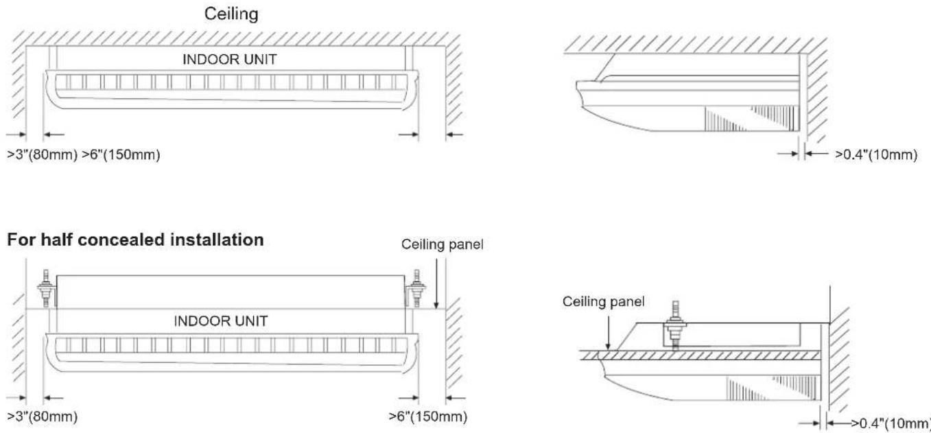
INSTALLING THE INDOOR UNIT
Connection pipe requirement
| Model | Diameter | Maximum length | Maximum height (between indoor and outdoor) | |
| Liquid side | Gas side | |||
| AC28ES1ERA AC36ES1ERA | 9.52 mm | 15.88mm | 30 m | 20m |
| AC48FS1ERA AC60FS1ERA | 9.52 mm | 19.05mm | 50 m | 30 m |
Install the room air conditioner as follows
1. Remove the intake grill and side cover
(1) Remove the Air filters
(2) Remove the intake grilles
(3) Remove the Side cover (Right and left side)
(4) This air conditioner can be set up to intake fresh air. The information about how to install for fresh-air intake, refer to "Fresh air intake".
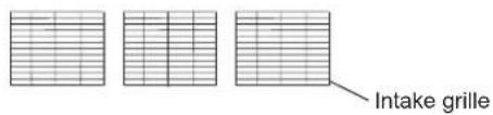
text_image
Intake grille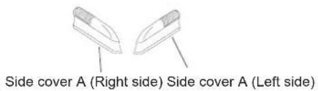
text_image
Side cover A (Right side) Side cover A (Left side)2. Location of ceiling suspension bolts
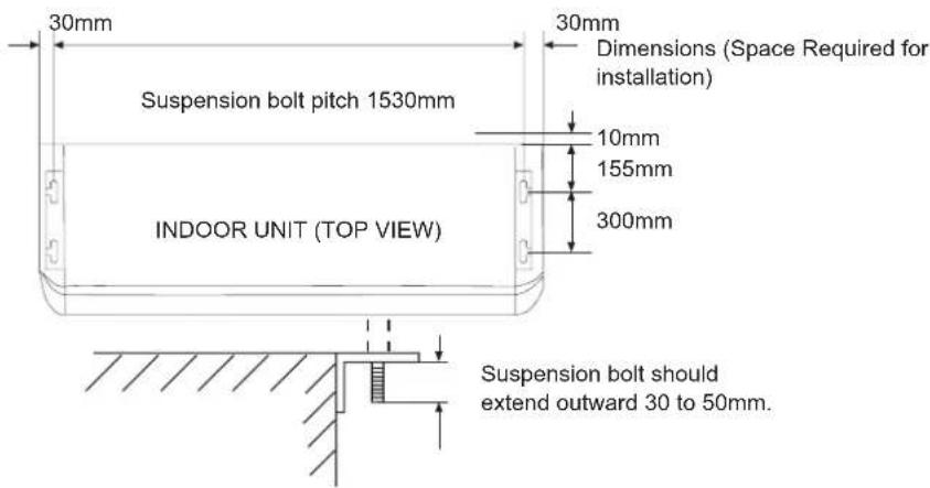
text_image
30mm Suspension bolt pitch 1530mm INDOOR UNIT (TOP VIEW) 30mm Dimensions (Space Required for installation) 10mm 155mm 300mm Suspension bolt should extend outward 30 to 50mm.For half-concealed installation
Supension-bolt pitch should be as shown below
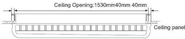
text_image
Ceiling Opening:1530mm40mm 40mm Ceiling panel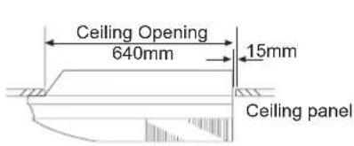
text_image
Ceiling Opening 640mm 15mm Ceiling panel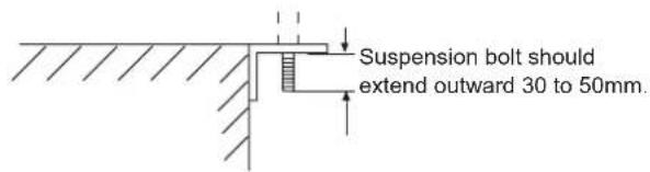
text_image
Suspension bolt should extend outward 30 to 50mm.Installation Procedure
3. Drilling the holes and attaching the suspension bolts
(1) Drill 25mm holes at the suspension-bolt locations. The two special nuts are provided with the unit. The M10 nut must be obtained locally.
(2) Install the bolts, then temporarily attach Special nuts A and B and a normal M10 nut to each bolt.
Bolt strength: 980 to 1470 N (100 TO 150 kgf)
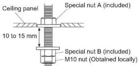
text_image
Ceiling panel Special nut A (included) 10 to 15 mm Special nut B (included) M10 nut (Obtained locally)If using anchor bolts
(1) Drill holes for anchor bolts at the locations at which you will set the suspension bolts. Note that anchor bolts must be obtained locally.
(2) Install the anchor bolts, then temporarily attach special nut "B" (included) and a locally-procured M10 nut to each of the bolts.
Anchor-bolt strength: 980 to 1470 N (100 TO 150 kgf)
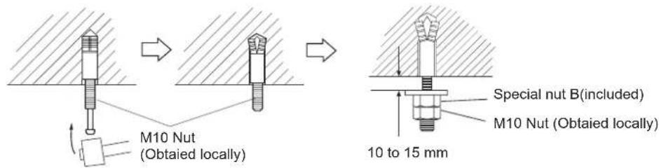
text_image
M10 Nut (Obtailed locally) Special nut B(included) M10 Nut (Obtailed locally) 10 to 15 mm4. Installing the indoor unit
(1) Lift unit so that suspension bolts pass through suspension fittings at the sides (four places), and slide the unit back.
(2) Fasten the indoor unit into place by tightening-up the special "B" bolts and the M10 nuts. Make sure that unit is secure and will not shift back and forth.
For half-concealed installation
When installing the indoor unit in a semi-concealed orientation, make sure to reinforce the insulation of the unit on all sides. Drops of water may fall from the unit if it is not thoroughly insulated.
CAUTION
In order to check the drainage, be sure to use a level during installation of the indoor unit. If the installation site of the indoor unit is not level, water leakage may occur.
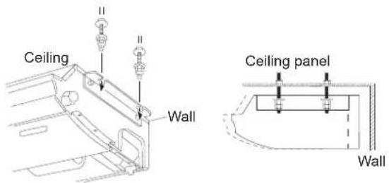
text_image
Ceiling Wall Ceiling panel Wall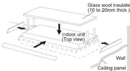
text_image
Glass wool insulate (10 to 20mm thick ) Indoor unit (Top view) Wall Ceiling panel5. Installing the coupler heat insulation
After checking for gas leaks, insulate by wrapping insulation around the two parts (large and small) of the indoor unit coupling, using the coupler heat insulation. After installing the coupler heat insulation, wrap both ends with vinyl tape so that there is no gap. Secure both ends of the heat insulation material using nylon fasteners.
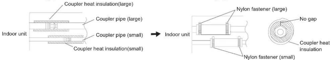
text_image
Coupler heat insulation(large) Coupler pipe (large) Coupler pipe (small) Coupler heat insulation(small) Indoor unit Nylon fastener (large) No gap Coupler heat insulation Nylon fastener (small)When using an auxiliary pipe, make sure that the fastener used is insulated in the same way.
Note:
When installing the unit on the floor, fix the four rubber base feet in the accessories on the bottom plate of the unit with four 4x16 screws and 4 flat washers, as the position in the figure.
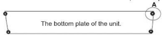
text_image
The bottom plate of the unit.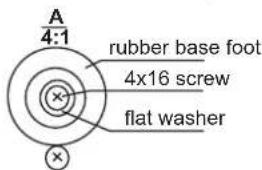
text_image
A 4:1 rubber base foot 4x16 screw flat washerINSTALLING THE DRAIN HOSE
• Install the drain pipe with downward gradient (1/50 to 1/100) and so there are no rises or traps in the pipe.
- Use general hard polyvinyl chloride pipe (VP25) (outside diameter 38 mm)
- During installation of the drain pipe, be careful to avoid applying pressure to the drain point of the unit.
- When the pipe is long, install supporters.
- Do not perform air bleeding.
• Always heat insulate (8mm or over thick) the indoor side of the drain pipe.
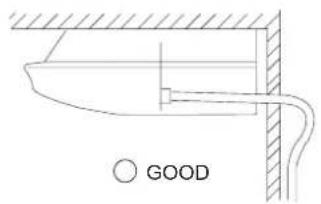
text_image
GOOD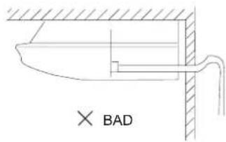
text_image
× BAD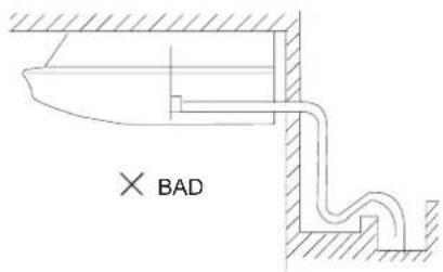
text_image
× BAD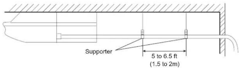
text_image
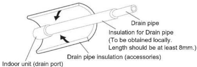
Supporter 5 to 6.5 ft (1.5 to 2m)(1) Install insulation for the drain pipe
Cut the included insulation material to an appropriate size and adhere it to the pipe.
text_image
Drain pipe Insulation for Drain pipe (To be obtained locally. Length should be at least 8mm.) Drain pipe insulation (accessories) Indoor unit (drain port)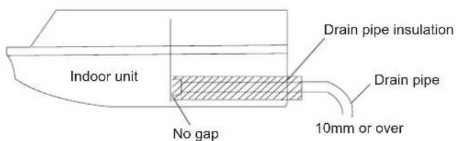
text_image
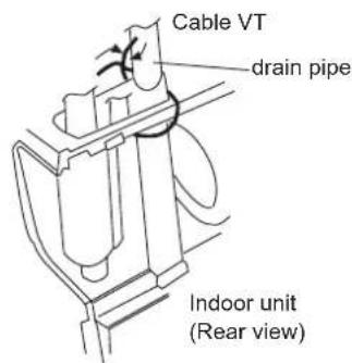
Indoor unit No gap Drain pipe insulation Drain pipe 10mm or over(2) When drain pipe is put in the right rear position
Fasten the drain pipe with cable VT so that there is a proper slope for drain pipe to exit from the indoor unit.
text_image
Cable VT drain pipe Indoor unit (Rear view)ELECTRICAL WIRING
Connect wiring to the terminals
A. For solid core wiring (or F-cable)
(1) Cut the wire end with a wire cutter or wire-cutting pliers, then strip the insulation to about 15/16"(25mm) to expose the solid wire.
(2) Using a screwdriver, remove the terminal screw(s) on the terminal board.
(3) Using pliers, bend the solid wire to form a loop suitable for the terminal screw.
(4) Shape the loop wire properly, place it on the terminal board and tighten securely with the terminal screw using a screwdriver.
B. For strand wiring
(1) Cut the wire end with a wire cutter or wire-cutting pliers, then strip the insulation to about 3/8"(10mm) to expose the solid wire.
(2) Using a screwdriver, remove the terminal screw(s) on the terminal board.
(3) Using a round terminal fastener or pliers, securely clamp a round terminal to each stripped wire end.
(4) Position the round terminal wire, and replace and tighten the terminal screw using a screwdriver.
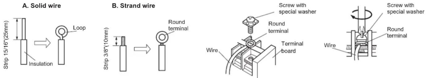
text_image
A. Solid wire Strip 15/16"(25mm) Insulation Loop B. Strand wire Strip 3/8"(10mm) Round terminal Screw with special washer Round terminal Terminal board Wire Wire Screw with special washer Round terminalFix connection cord and power cable at the cord clamp
After passing the connection cord and power cable through the insulation tube, fasten it with the cord clamp.
Use VW-1, 0.5 to 1.0 mm thick, PVC tube as the insulation tube.
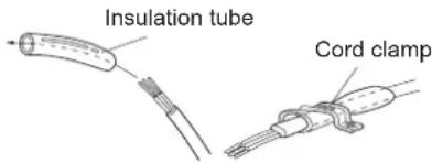
text_image
Insulation tube Cord clampElectrical requirement
Select wire sizes and circuit protection from table below. (This table shows 20m length wires with less than 2% voltage drop).
| Model\Item | Phase | Circuit breaker | Power source wire size (minimum) ( mm^2 ) | Earth leakage breaker | ||
| Switch breaker (A) | Overcurrent protector rated capacity (A) | Switch breaker(A) | Leak current(mA) | |||
| AC28ES1ERA AC36ES1ERA | 1 | 40 | 30 6.0 | 40 | 30 | |
| AC48FS1ERA AC60FS1ERA | 1 30 | 4.0 1020 30 | ||||
CAUTION
- Match the terminal block numbers and connection cord colors with those of the outdoor unit. Erroneous wiring may cause burning the electric parts.
- Connect the connection cords firmly to the terminal block. Imperfect installation may cause a fire.
- Always fasten the outside covering of the connection cord with the cord clamp. If the insulator is chafed, electric leakage may occur.
• Always connect the ground wire. - The Unit has default temperature compensation setting, please cancel it when floor standing installation.
Connect indoor unit and outdoor unit
(1) Remove the cord clamp.
(2) Process the end of the connection cords to the dimensions shown in wiring diagram.
(3) Connect the end of the connection cord fully into the terminal block.
(4) Fasten the connection cord with a cord clamp.
(5) Fasten the end of the connection cord with the screw.
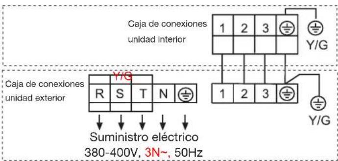
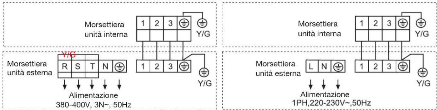
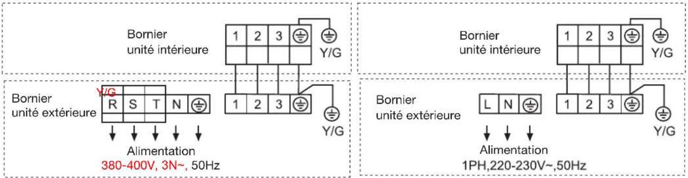
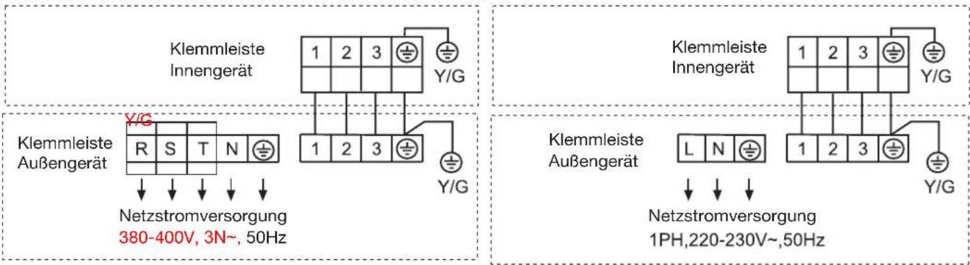
Wiring diagram
AC28ES1ERA AC36ES1ERA AC48FS1ERA AC60FS1ERA
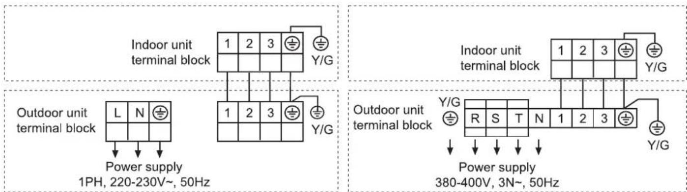
text_image
Indoor unit terminal block 1 2 3 Y/G Outdoor unit terminal block L N Power supply 1PH, 220-230V~, 50Hz 1 2 3 Y/G Indoor unit terminal block 1 2 3 Y/G Outdoor unit terminal block Y/G R S T N 1 2 3 Power supply 380-400V, 3N~, 50HzWARNING
• The power cable and connecting cable are self-provided.
• Always use a special branch circuit and install a special receptacle to supply power to the room air conditioner.
- Use a circuit breaker and receptacle matched to the capacity of the room air conditioner.
- The circuit breaker is installed in the permanent wiring. Always use a circuit that can trip all the poles of the wiring and has an isolation distance of at least 3mm between the contacts of each pole.
- Perform wiring work in accordance with standards so that the room air conditioner can be operated safely and positively.
• Install a leakage circuit breaker in accordance with the related laws and regulations and electric company standards.
CAUTION
- The power source capacity must be the sum of the room air conditioner current and the current of other electrical appliances. When the current contracted capacity is insufficient, change the contracted capacity.
- When the voltage is low and the air conditioner is difficult to start, contact the power company the voltage raised.
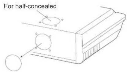
FRESH AIR INTAKE
- Open up the knockout hole for the fresh air intake. If using half-concealed installation, open up the top knockout hole instead.
CAUTION
- When removing the cabinet (iron plate), be careful not to damage the indoor unit internal parts and surrounding area (outer case).
-
When processing the cabinet (iron plate), be careful not to injury yourself with burrs,etc.
-
Fasten the round flange (optional) to the fresh air intake. If using half-concealed installation, attach to the top.
- Connect the duct to the round flange.
- Seal with a band and vinyl tape, etc. so that air does not leak from the connection.
text_image
For half-concealed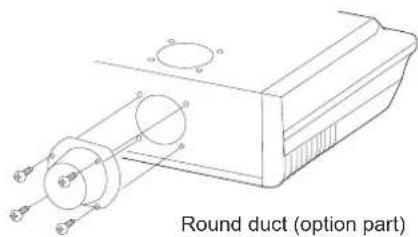
text_image
Round duct (option part)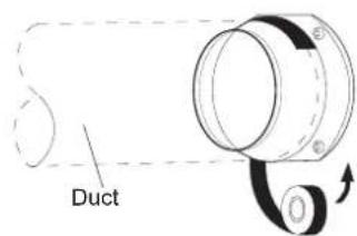
text_image
DuctCheck items
1. Indoor unit
• Is operation of each button on the remote control unit normal?
- Does each lamp light normally?
- Do not air flow direction louvers operate normally?
• Is the drain normal?
2. Outdoor unit
• Is there any abnormal noise and vibration during operation?
- Will noise, wind, or drain water from the unit disturb the neighbors?
• Is there any gas leakage?
Customer guidance
Explain the following to the customer in accordance with the operation manual:
(1) Starting and stopping method, operation switching, temperature adjustment, timer, air flow switching, and other remote control unit operations.
(2) Air filter removal and cleaning, and how to use air louvers.
(3) Give the operation and installation manuals to the customer.
Haier
Address: No.1 Haier Road, Hi-tech Zone, Qingdao 266101 P.R.China
Contacts: TEL +86-532-8893-6943;FAX +86-532-8893-6999
Website: www.haier.com

natural_image
Pure electrical circuit lines without any symbolsAC28ES1ERA AC36ES1ERA
natural_image
Front view of a white air conditioner unit with ventilation grilles and a red 'Holar' logo (no visible text or symbols beyond branding)AC48FS1ERA AC60FS1ERA
Contenido
text_image
Technical diagram of a refrigerated storage unit with numbered components and internal structure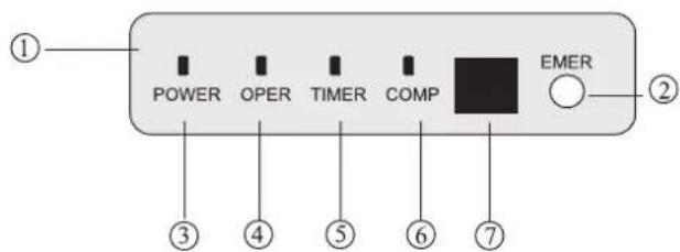
text_image
① POWER OPER TIMER COMP EMER ② ③ ④ ⑤ ⑥ ⑦text_image
Diagram of a battery pack with labeled components and directional arrows indicating movement or forcenatural_image
Close-up of a person lying in bed, wearing a white blanket with soft hair (no visible text or symbols)natural_image
Architectural line drawing of a building facade with grid patterns and structural elements (no text or symbols)text_image
Techo Pared Techo Pared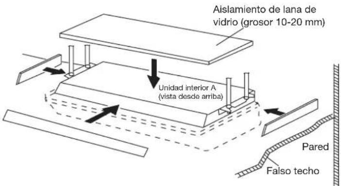
natural_image
Technical line drawing of a mechanical assembly with no visible text or symbols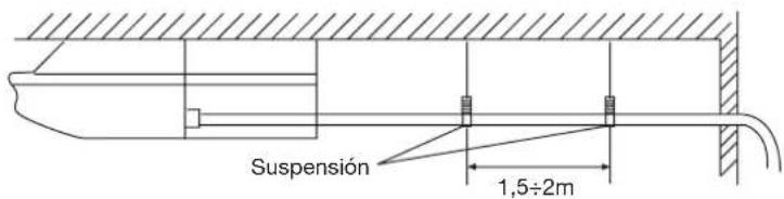
AC48FS1ERA AC60FS1ERA AC28ES1ERA AC36ES1ERA
natural_image
Pure electrical circuit lines without any symbolsAC28ES1ERA AC36ES1ERA
natural_image
Front view of a white air conditioner unit with ventilation grilles and a red 'Haier' logo (no visible text or symbols on the device itself)AC48FS1ERA AC60FS1ERA
Indice
GWP=global warming potential
text_image
Diagram of a battery pack with labeled components and directional arrows indicating movement or forcenatural_image
Person sleeping in bed with soft white bedding (no visible text or symbols)natural_image
Architectural line drawing of a window frame structure with grid patterns (no text or symbols)natural_image
Pure technical diagram showing a cross-section of a structural joint or channel with hatched areas and no text, numbers, or symbols.AC48FS1ERA AC60FS1ERA AC28ES1ERA AC36ES1ERA
natural_image
Technical line drawing of a mechanical component with circular features and a pointer (no text or symbols)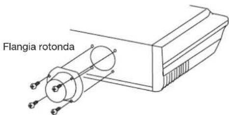
text_image
Flangia rotonda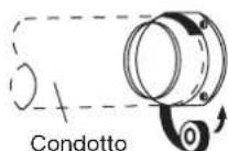
Unità interna
natural_image
Pure electrical circuit lines without any symbolsAC28ES1ERA AC36ES1ERA
natural_image
Front view of a white air conditioner unit with ventilation grilles and a red 'Meater' logo (no visible text or symbols on the device itself)AC48FS1ERA AC60FS1ERA
Table des matières
text_image
Diagram of a battery pack with labeled components and directional arrows indicating movement or forcenatural_image
Close-up of a person sleeping in bed, wearing a white blanket (no text or symbols visible)natural_image
Architectural line drawing of a window frame structure with grid patterns (no text or symbols)AC48FS1ERA AC60FS1ERA AC28ES1ERA AC36ES1ERA
natural_image
Technical line drawing of a mechanical component with circular features and a pointer (no text or symbols)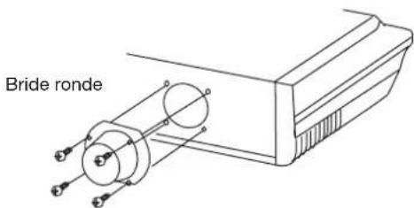
text_image
Bride ronde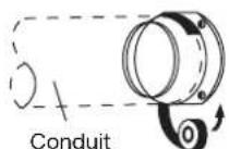
Unité intérieure
natural_image
Front view of a white air conditioner unit with yellow indicator lights (no text or symbols visible)AC28ES1ERA
AC36ES1ERA
natural_image
Front view of a white air conditioner unit with red 'Holar' branding and ventilation grille (no readable text beyond brand name)AC48FS1ERA
AC60FS1ERA
Inhalt
text_image
Diagram of a battery pack with labeled parts and directional arrows indicating movement or assembly.natural_image
Close-up of a person sleeping in bed with soft lighting (no visible text or symbols)Betriebsart
natural_image
Architectural wireframe diagram of a building facade with grid patterns and structural elements (no text or symbols)AC48FS1ERA AC60FS1ERA AC28ES1ERA AC36ES1ERA
natural_image
Technical line drawing of a mechanical component with two circular features and a base (no text or symbols)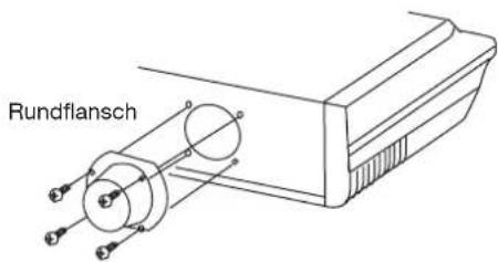
text_image
Rundflansch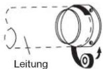
Innengerät
Adresse: No.1 Haier Road, Hi-tech Zone, Qingdao 266101, VR-China
Kontakt: TEL +86-532-8893-6943; FAX +86-532-8893-6999
Website: www.haier.com
