
ACG201 - Electric oven FAGOR - Free user manual and instructions
Find the device manual for free ACG201 FAGOR in PDF.

| Product type | Professional electric oven |
| Brand | Fagor |
| Model | ACG201 |
| Power supply | 230 V / 400 V (depending on version) |
| Cooking modes | Convection, Steam (99 °C), Combination, Regeneration |
| Temperature range (convection) | 20 °C to 300 °C |
| Temperature range (combination) | 20 °C to 250 °C |
| Steam temperature | 99 °C (fixed) |
| Timer | Up to 300 minutes |
| Core probe function | Yes, with core temperature display |
| Delta function | 50 °C difference between probe and oven (optional) |
| Cool down function | Automatic cooling down to 45 °C |
| Humidifier | Rapid moisture injection for rising |
| Display | Digital with mode indicators |
| Control | Push buttons and rotary selectors |
| Chamber material | Stainless steel |
| Cleaning | Manual with recommended steam cycle |
| Safety | Self-diagnosis with error codes (001-025) |
| Usage | Professional |
| Burner lock (gas models) | Yes, with indicator and reset |
Frequently Asked Questions - ACG201 FAGOR
User questions about ACG201 FAGOR
0 question about this device. Answer the ones you know or ask your own.
Ask a new question about this device
Download the instructions for your Electric oven in PDF format for free! Find your manual ACG201 - FAGOR and take your electronic device back in hand. On this page are published all the documents necessary for the use of your device. ACG201 by FAGOR.
USER MANUAL ACG201 FAGOR
20560 Oñati (Gipuzkoa/Spain)
INDICE
INDICE ....3
ELEMENTOS DE MANDO......4
ELEMENTOS DE MANDO CONCEPT GAS....4
ELEMENTOS DE MANDO CONCEPT ELECTRICO....5
START / STOP
natural_image
Simple line drawing of a trash bin with crossed lines indicating no waste or restriction (no text or symbols)natural_image
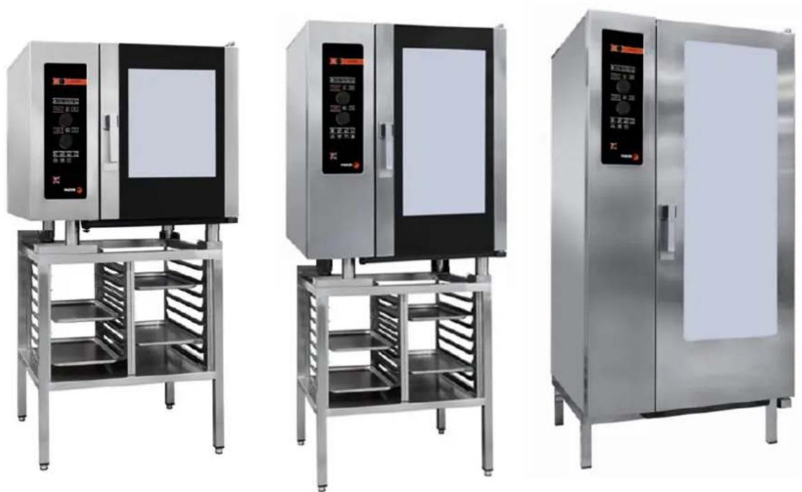
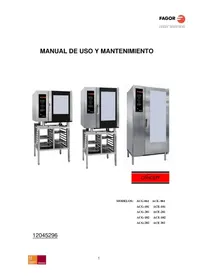
Three stainless steel laboratory ovens with control panel designs, displayed side by side (no visible text or labels)
MODELOS: ACG-061 ACE-061
ACG-101 ACE-101
ACG-201 ACE-201
ACG-102 ACE-102
ACG-202 ACE 202
12045296
DEAR CUSTOMER
We would like to thank you for the confidence you have shown in our product on purchasing a professional appliance. We are totally convinced that in time you will be completely satisfied with your purchase.
Take a few minutes of your time and get to know the appliance with this instructions manual and "down to work": the easy to understand graphical information replaces pages full of writing.
Nevertheless, we recommend you thoroughly read this manual compiled by FAGOR's kitchen supervisors, in order to benefit to the maximum from the multiple possibilities and advantages this appliance offers you.
Keep this manual near to the appliance and at all times in an accessible place.
Lastly, we wish you success and hope that you will be fully satisfied with your new oven.

FAGOR INDUSTRIAL S. COOP.
B\ Santxolopetegi 22 aptdo 17
20560 Oñati (Gipuzkoa/Spain)
CONTENTS
CONTENTS....19
CONTROLS 20
CONCEPT GAS COOKING MODES 20
CONCEPT ELECTRIC COOKING MODES 21
SELECTION OF CONCEPT COOKING MODES....22
TEMPERATURE SELECTION....22
TIME SELECTION 23
POWER / SPEED SELECTION....23
AUXILIARY FUNCTIONS....23
CORE PROBE SPIKE (OPTIONAL): 24
DELTA FUNCTION 25
COOL DOWN 26
HUMIDIFIER BUTTON 26
LOCK INDICATOR BURNER (GAS MODELS) 26
START / STOP 27
OPERATION OF THE CONCEPT OVEN....27
MAINTENANCE....28
MANUAL CLEANING 28
PROBLEMS 29
TYPES OF FAULT....30
ENVIRONMENTAL PROTECTION RECOMMENDATION 32
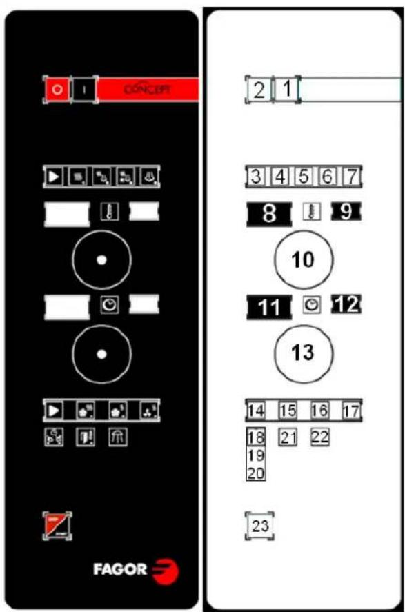
CONTROLS
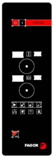
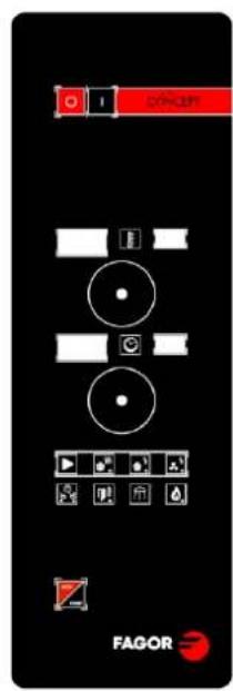
Concept Gas Serigraph
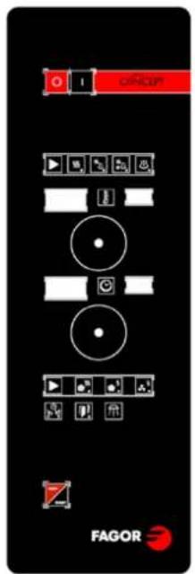
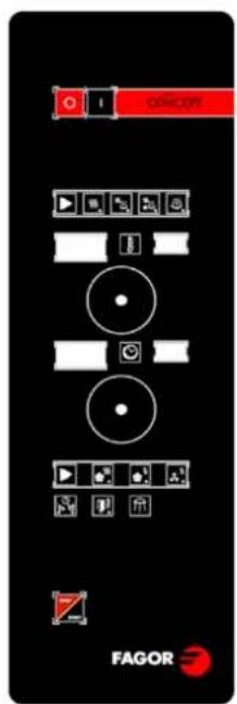
Concept Electric Serigraph
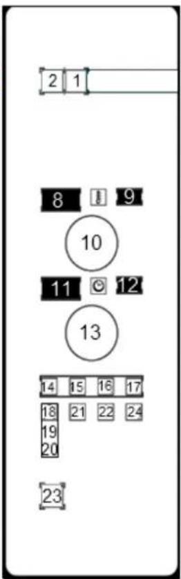
CONCEPT GAS COOKING MODES
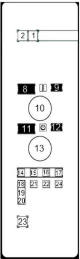
1-Turning the oven on
2-Turning the oven off
8-Chamber temperatura actual value
9-Chamber temperature setpoint
10-Temperature selector
11-Remaining time value
12-Time Setpoint
13-Time Selector
14-Power / Speed Selector
15-Max Power / Max Speed Display
16-Min Power / Max Speed Display
17-Min Power / Min Speed Display
18-19-20-Function Selector -Spike function Display-Delta function Display
21-Cool down button / Display
22-Button / Humidify
24-Burner block
23-Start / Stop button
CONCEPT ELECTRIC COOKING MODES
- Turning on the oven
- Turning off the oven
- Mode selection
- Convection mode indicator
- Mixed Mode Indicator
- Regeneration mode indicator
- Steam mode indicator
- Actual value of chamber temperature
- Chamber temperature setpoint
- Temperature selector
- Remaining time value
- Setpoint time
- Time selector
- Selector power / speed
15-Max Power / Max Speed Display
16-Min Power / Max Speed Display
17-Min Power / Min Speed Display - Function switch
- Spike indicator function
- Delta function indicator
- Button / Indicator cool down
- Button / Humidify
- Push button Start / Stop
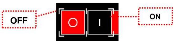
ON/OFF
The oven is switched on/off with the main ON/OFF switch. Each time that the oven is switched on, the last-used values are displayed. If this is the first time the oven is switched on, the defect values are displayed.
flowchart
graph LR
    A["OFF"] --> B["Red Circle"]
    B --> C["I"]
    C --> D["ON"]
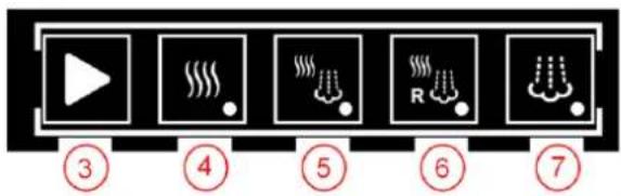
SELECTION OF CONCEPT COOKING MODES
Use the mode 3 selector button.
- Mode selector.
- Convection mode indicator.
- Mixed-mode indicator.
- Regeneration mode indicator
-
Indicator steam mode.
-
CONVECTION: The oven is only heated with hot air (dry heat).
- STEAM: The oven is heated using steam from the injection of water at 99°C at atmospheric pressure.
- MIXED: The oven is heated using a combination of hot air and steam.
- REGENERATION: The heating by hot air and steam at a time, but at higher power to steam.
The fluepipe opens automatically in convection mode. In all other modes it remains closed.
TEMPERATURE SELECTION
Use the temperature selection button (control 10) to select the required temperature in the oven interior. This is displayed in window 9 (chamber temperature setting).
Window 8 shows the true value of the temperature in the chamber.
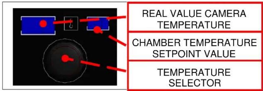
The temperature range and defect values for each operating mode are listed below:
- Convection: Range [20..300].
- Mixed: Range [20.0.250].
- Steam: Range [99].
TIME SELECTION
○ Remaining time: Numerical value which shows the time remaining until the selected cooking mode is completed.
When the time reaches 0, the number starts to flash, the horn is heard and the light flashes in time with the horn until the door is opened or for a maximum of 30 seconds. If the door is not opened, the acoustic/visual warning is repeated for 30 seconds every 3 minutes.
○ Time setting: Time setting selected by the user. The maximum possible time is 300 minutes. When the operating mode is changed, the last-used value in this mode is automatically loaded.
natural_image
Diagram showing a blue rectangular object with red lines and a black circular component, no text or symbols present.TIME REMAINING
DELIVERY TIME
TIME SWITCH
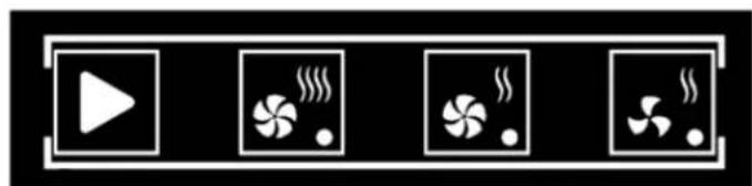
POWER / SPEED SELECTION
natural_image
Four white play button icons with fan symbols, arranged horizontally on black background (no text or labels)14
15
16
17
AUXILIARY FUNCTIONS
18
19
20

21

22

24
MODELO DE GAS
14- Power / speed selector button.
15- Maximum power / maximum speed display.
16- Average power / maximum speed display.
17- Average power / average speed display.
18-.19-20-Temperature / spike / delta (optional) selector button.
21- Button / Cool down display.
22- Humidifier button.
24-Lock burner
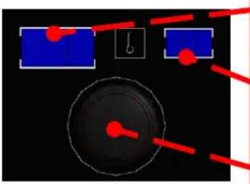
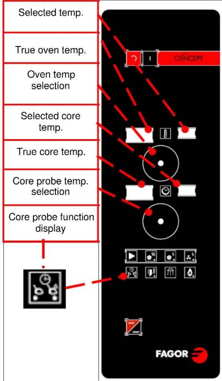
CORE PROBE SPIKE (OPTIONAL):
Select by pressing button 17 and with the core probe display lit.
flowchart
graph TD
    A["Selected temp."] --> B["True oven temp."]
    B --> C["Oven temp selection"]
    C --> D["Selected core temp."]
    D --> E["True core temp."]
    E --> F["Core probe temp. selection"]
    F --> G["Core probe function display"]
    G --> H["FAGOR"]
Turn control 13 to select the required core temperature.
Window 12 displays the selected core temperature from 0 to 99°C.
Window 11 displays the true temperature in the core probe.
Turn control 10 to select the oven chamber temperature.
Window 8 displays the selected oven temperature.
Window 8 displays the true temperature in the oven chamber.
When the core temperature reaches the required temperature, the oven stops and an alarm is heard.
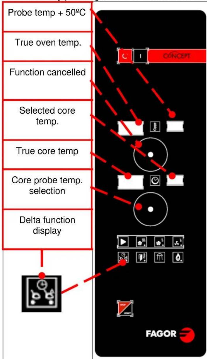
DELTA FUNCTION
Difference between the core temperature and the oven temperature.
The oven temperature is always 50^ C higher than the temperature recorded by the core probe.
Select by pressing button 17 and with the delta display lit.
flowchart
graph TD
    A["Probe temp + 50°C"] --> B["True oven temp."]
    B --> C["Function cancelled"]
    C --> D["Selected core temp."]
    D --> E["True core temp"]
    E --> F["Core probe temp. selection"]
    F --> G["Delta function display"]
    G --> H["FAGOR"]
Turn control 13 to select the required core temperature (for example 70^ C) displayed in window 12.
Insert spike probe in food (for example 15^ C) displayed in window 11.
The oven will heat up to 15^+50^ 65^ and as the temperature of the core rises, the oven temperature will increase, always maintaining a difference of +50^ .
When the core temperature reaches the selected 70^ C, the oven temperature is 120^ C and an alarm will be heard.
In this function, control 10 (for selecting the oven temperature) is inoperative.
In steam mode, set at 99^ C, the adjustment range is only from 0 to 49^ C.
In the convection and mixed modes, the adjustment range is from 0 to 99°C.
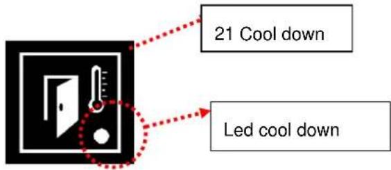
COOL DOWN
To cool the cooking chamber, proceed as follows:
Close the door and press button 21 (COOL DOWN). Next open the door.
The fan starts and the cool down LED indicator light, number 21, lights up. When the chamber temperature reaches 45^ , the fan stops automatically.
The cooling cycle can be stopped by pressing button 20 again or by closing the door, and the cool down indicator will go out.
Warning: Do not cool the oven by directly applying cold water in the tub.
SAFETY MEASURES: The fan cover and the tray guides must be correctly fastened in place during this cycle.
The cooking chamber must not be cooled with cold water.
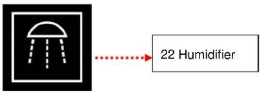
HUMIDIFIER BUTTON
The moisture inlet only operates when button 21 is pressed in Start mode (in Stop mode the signal is ignored).
Bakery products rise very well using this function thanks to the rapid entrance of moisture.
Soft shine to baked products.
It should be used for short periods of time.
flowchart
graph LR
    A["Shutter Icon"] --> B["22 Humidifier"]
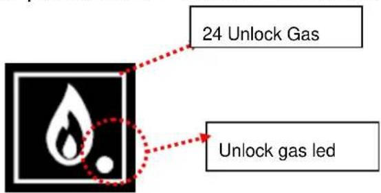
LOCK INDICATOR BURNER (GAS MODELS)
The gas burners can be blocked for different reasons. In this situation the burner lock indicator is activated and warns that it is necessary to unlock.
To unlock, press the reset key 24 gas, and press START / STOP to resume operation of the furnace.
START / STOP
The oven starts to operate with the settings entered in cooking, temperature and time mode when the START/STOP button is pressed once.
If the button is pressed again, the operation is stopped and the oven is in pause mode.
If a set time has been selected, pressing the START/STOP button a second time implies that the cooking time is interrupted and the time is reset to the previously selected value.

Procedure to start a FAGOR CONCEPT oven.
- Press the ON button (1).
- Select cooking mode (3).
- Select time (9).
- Select temperature (12).
- Select time/spike/delta function (17) (optional).
- Press START/STOP (22).
MAINTENANCE
MANUAL CLEANING
The appliance should be cleaned every day.
The appliance must always be switched off for cleaning.
For the correct working and maintenance of the appliance, it should be cleaned every day using degreasing products specifically designed for this.
VERY IMPORTANT: Sand-based or abrasive products must not be used. Nor should a hose be used to clean the outside of the appliance as this could affect the internal components.
The appliance must always be switched off for Manual Cleaning.
The procedure for Manual Cleaning is as follows:
1 Cool the oven to 60^ C, (use the oven cooling function), and then remove all solid waste.
2 Spray the inside of the chamber evenly with the detergent.
3 Close the door and allow the detergent to operate for 5 or 10 minutes (depending on the type of dirt).
4 Continue with a steam cycle for 5 to 10 minutes, then stop the oven and carefully open the door.
WARNING: The detergents are highly active and therefore extreme caution should be taken as they could cause irritation to the skin or eyes. The manufacturer's instructions must be strictly observed.
6 Rinse with plenty of water. The shower supplied with the appliance (optional in all versions) may be used.
Note: The appliance has been designed to permit water to be sprayed all over the cooking chamber without any risk of damage, to allow thorough cleaning and the perfect rinse.
7 Dry the oven, using the convection mode for 5 minutes. Next, disconnect the power supply, close the water cut-off taps and leave the door ajar to ensure that the air inside the oven remains fresh.
If the oven is cleaned everyday, the operation can be completed within 15 minutes, giving an appliance in perfect condition ad ready for work the next day.
As the door reverse is made of glass, it is very easy to clean, using the same products used to clean vitroceramic hobs.
1 Use the scraper to remove any grease incrusted on the glass.
2 Spray the product on the glass.
3 Wipe the glass clean with a cloth.
Note: Do not use products or tools which may scratch the glass.
PROBLEMS
In the event of a fault or the incorrect operation of the appliance, before calling the technical assistance service, please check that:
■ the fuses are correct.
■ the voltage is correct
■ the mains water pressure is correct.
- if steam comes out through the door, the door seal may be dirty. If this is the case, it should be cleaned.
- If water is observed dripping on the floor, the drainage may be blocked. In this case, clean through the plug in the lower part of the appliance.
This model has a self-diagnosis programme. In the event of a fault the appliance is blocked and an error message is displayed on the digital displays.
This appliance is only for professional use and must be used qualified personnel.
TYPES OF FAULT
When an error occurs:
■ The bell rings intermittently.
- The code and error identification are displayed in the oven windows.
- If the START/STOP button is pressed, the error message continues to be displayed but the bell stops ringing.
- When the fault causing the error is removed, the outputs return to normal operation.
The errors which may occur in the oven are listed below, together with the message displayed and the impact on the operation of the oven.

ERROR 001
DESCRIPTION
Camera probe broken. TC out of range.
CONSEQUENCE
The oven is completely disabled

ERROR 003
DESCRIPTION
Steam outlet temperature probe (TV) faulty. TV out of range [-5..330]
CONSEQUENCE
It is only possible to operate in Convection mode, omitting water condensation.
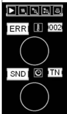
ERROR 002
DESCRIPTION
Core probe (TN) faulty. TN out of range [-10..330]
CONSEQUENCE
The spike and delta function is disabled
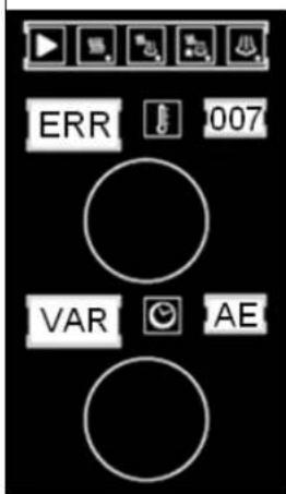
ERROR 007
DESCRIPTION
• There is no communication with the speed variator.
- If the motor does not start within 10 seconds of a start request.
- If a speed of 500 rpm is not exceeded within 20 seconds of a start request.
CONSEQUENCE
The oven is completely
disabled
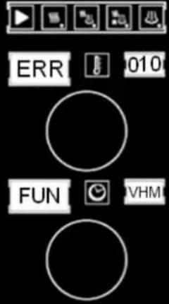 | ERROR 010DESCRIPTIONIf the VHM outlet is activated and TV does not rise 3 or more degrees in 2 minutes, if TV<=75.CONSEQUENCEIt is only possible to operate in Convection mode | 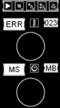 | ERROR 023DESCRIPTIONFluepipe motor faultyCONSEQUENCEThe oven is completely disabled |
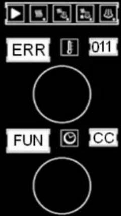 | ERROR 011DESCRIPTIONThe CC output operates for 12 minutes and TC does not rise 3 or more degrees.CONSEQUENCEThe oven is completely disabled. | 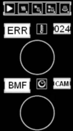 | ERROR 024DESCRIPTIONCommunication error. The chamber card does not respond.CONSEQUENCEThe oven is completely disabled |
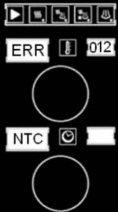 | ERROR 012DESCRIPTIONThe controller NTC reaches 60°C, but does not exceed 70°C.CONSEQUENCEThe oven operates normally and the bell is not heard. This message should be displayed every 3 minutes for 30 seconds. |  | ERROR 025DESCRIPTIONCommunication error. The control holder card does not respond.CONSEQUENCEThe oven is completely disabled |
 | ERROR 022DESCRIPTIONThe controller NTC exceeds 70°C.CONSEQUENCEThe oven is completely disabled. | ||
ENVIRONMENTAL PROTECTION RECOMMENDATION
On ending its useful life, this product must not be thrown away in a standard rubbish bin, but must be left in an electrical waste and electronic equipment collection point for recycling.
This is confirmed by the symbol on the product, user manual, or packaging.
Depending on the symbol, the materials can be recycled. By recycling and other ways of processing electrical waste and electronic equipment, you can significantly contribute to protecting the environment.
Contact your local authorities for more information of the nearest collection point.
To preserve the environment at the end of the useful life of your product, leave it in the appropriate places in accordance with the current legislation.
NOTE: THE FINAL USER OF THE PACKAGING WASTE IS RESPONSIBLE FOR ITS DISPOSAL.
natural_image
Symbol of a trash bin crossed with two diagonal lines, representing no waste or discharge (no text or labels)natural_image
Three stainless steel laboratory ovens with control panel designs, displayed side by side (no visible text or labels)
MODELLE: ACG-061 ACE-061
ACG-101 ACE-101
ACG-201 ACE-201
ACG-102 ACE-102
ACG-202 ACE 202
12045296
20560 Oñati (Gipuzkoa/Spain)
INHALTSVERZEICHNIS
15-INDICATOR Pot max / vel max
16-Geschwindigkeit
natural_image
Symbol of a trash bin crossed with two diagonal lines, representing no waste or discharge (no text or labels)UTILISER ET MAINTENANCE
natural_image
Three stainless steel laboratory ovens with control panel designs, displayed side by side (no visible text or labels)
MODÈLES : ACG-061 ACE-061
ACG-101 ACE-101
ACG-201 ACE-201
ACG-102 ACE-102
ACG-202 ACE 202
12045296
CHER CLIENT
20560 Oñati (Gipuzkoa/Spain)
TABLE DES MATIÈRES
TABLE DES MATIÈRES....51
ÉLÉMENTS DE COMMANDE....52
ÉLÉMENTS DE COMMANDE DE GAZ CONCEPT ....52
ELEMENTS DE COMMANDE CONCEPT ÉLECTRIQUE ....53
SÉLECTION DES MODES DE CUISSON CONCEPT ....54
SÉLECTION TEMPÉRATURE....54
SÉLECTION DU TEMPS....54
SÉLECTION PUISSANCE / VITESSE ....55
FONCTIONS AUXILIAIRES....55
FONCTIONNEMENT FOUR CONCEPT ....59
ENTRETIEN 60
NETTOYAGE MANUEL 60
IRRÉGULARITÉS 61
TYPES DE DÉFAUTS....62
RECOMMANDATIONS RELATIVES À LA PROTECTION DE L'ENVIRONNEMENT....64
ÉLÉMENTS DE COMMANDE
Sérigraphie Concept Gaz
1-Allumez le four
2 - Eteindre le four
FONCTIONNEMENT FOUR CONCEPT
20560 Oñati (Gipuzkoa/Spain)
INDICE
INDICE 67
ELEMENTI DI COMANDO 68
ELEMENTI DI COMANDO COMCEPT GAS....68
ELEMENTI DI COMANDO COMCEPT ELECTTRICA....69
START / STOP
natural_image
Symbol of a trash bin crossed with two diagonal lines, representing no waste or discharge (no text or labels)


- INDICE
- START / STOP
- DEAR CUSTOMER
- CONTENTS
- CONCEPT ELECTRIC COOKING MODES
- ON/OFF
- SELECTION OF CONCEPT COOKING MODES
- TEMPERATURE SELECTION
- TIME SELECTION
- POWER / SPEED SELECTION
- AUXILIARY FUNCTIONS
- CORE PROBE SPIKE (OPTIONAL):
- DELTA FUNCTION
- COOL DOWN
- HUMIDIFIER BUTTON
- LOCK INDICATOR BURNER (GAS MODELS)
- MAINTENANCE
- MANUAL CLEANING
- PROBLEMS
- TYPES OF FAULT
- ERROR 001
- DESCRIPTION
- CONSEQUENCE
- ERROR 003
- ERROR 002
- ERROR 007
- ENVIRONMENTAL PROTECTION RECOMMENDATION
- INHALTSVERZEICHNIS
- UTILISER ET MAINTENANCE
- CHER CLIENT
- TABLE DES MATIÈRES
- TABLE DES MATIÈRES....51
- ÉLÉMENTS DE COMMANDE....52
- FONCTIONNEMENT FOUR CONCEPT ....59
- ENTRETIEN 60
- TYPES DE DÉFAUTS....62
- RECOMMANDATIONS RELATIVES À LA PROTECTION DE L'ENVIRONNEMENT....64
- ÉLÉMENTS DE COMMANDE
- FONCTIONNEMENT FOUR CONCEPT
- INDICE 67
- ELEMENTI DI COMANDO 68
Brand : FAGOR
Model : ACG201
Category : Electric oven