Airpower 4801090 - Compressor Güde - Free user manual and instructions
Find the device manual for free Airpower 4801090 Güde in PDF.

Frequently Asked Questions - Airpower 4801090 Güde
User questions about Airpower 4801090 Güde
0 question about this device. Answer the ones you know or ask your own.
Ask a new question about this device
Download the instructions for your Compressor in PDF format for free! Find your manual Airpower 4801090 - Güde and take your electronic device back in hand. On this page are published all the documents necessary for the use of your device. Airpower 4801090 by Güde.
USER MANUAL Airpower 4801090 Güde
natural_image
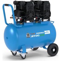
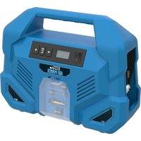
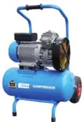
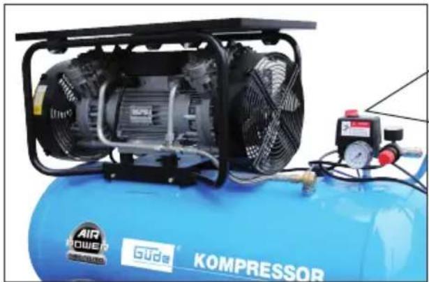
Blue KOMPRESSOR air compressor with visible engine and control panel (no text or symbols on body)480/10/90
50092

natural_image
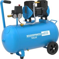
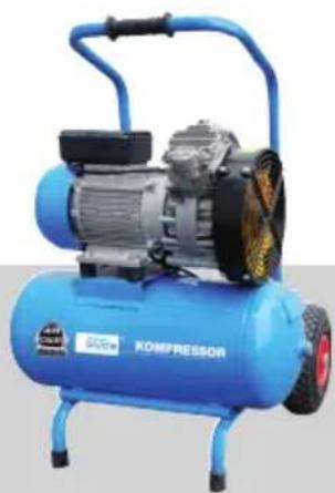
Blue industrial air compressor with visible motor and wheels (no text or symbols)350/10/25
50094

natural_image
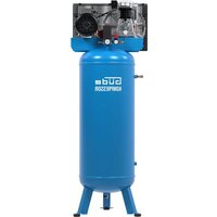
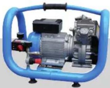
Blue industrial air compressor with motor and pump unit (no visible text or symbols)240/10/5
50096


ENGLISH Please read the instructions carefully before starting the machine.
English TECHNICAL DATA | SPECIFIED CONDITIONS OF USE | SAFETY INSTRUCTIONS | MAINTENANCE | GUARANTEE | EC-DECLARATION OF CONFORMITY 17
Français CARACTÉRISTIQUES TECHNIQUES | UTILISATION CONFORME À LA DESTINATION | CONSIGNES DE SÉCURITÉ | ENTRETIEN | GARANTIE | DÉCLARATION DE CONFORMITÉ CE \_\_\_\_ 22
text_image
Product catalog page showing three industrial machines with Chinese labels and a 'STO' button1
natural_image
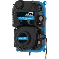
Blue Air Conditioner with internal air compressor and control panel (no visible text or symbols on body)2
3
2x

4
2x
5
2x
2x
6
[Non-Text]
7
2x

8
2x
0
Typ 350/10/25
2
9
2x

| DE | Montage | SI | Montaža |
| GB | Assembly | HR | Montaža |
| FR | Montage | BG | MONTAX |
| IT | Montaggio | RO | Montaj |
| NL | Montage | BA | Montaža |
| CZ | Montáž | ||
| SK | Montáž | ||
| HU | Szerelés |
| DE | Inbetriebnahme | SI | Uvedba v pogon |
| GB | Starting-up the machine | HR | Puštanje u rad |
| FR | mise en service | BG | Пускане в действие |
| IT | Messa in funzione | RO | Punerea în funcțiune |
| NL | Inbedrijfstelling | BA | Puštanje u rad |
| CZ | Uvedení do provozu | ||
| SK | Uvedenie do prevádzky | ||
| HU | Üzembe helyezés |
| DE | Betrieb | SI | Delovanje |
| GB | Operation | HR | Rad |
| FR | Fonctionnement | BG | Păbota |
| IT | Esercizio | RO | Funcționare |
| NL | Gebruik | BA | Rad |
| CZ | Provoz | ||
| SK | Prevádzka | ||
| HU | Üzemeltetés |
| DE | Reinigung / Wartung | SI | Čiščenje / Vzdrževanje |
| GB | Cleaning / Maintenance | HR | Čiščenje / Održavanje |
| FR | Nettoyage / Entretien | BG | Чистене / Поддръжка |
| IT | Pulizia / Manutenzione | RO | Curățare / Întreținere |
| NL | Schoonmaken / Onderhoud | BA | Čiščenje / Održavanje |
| CZ | Čištění / Údržba | ||
| SK | Čistenie / Údrzba | ||
| HU | Tisztítás / Karbantartás |
text_image
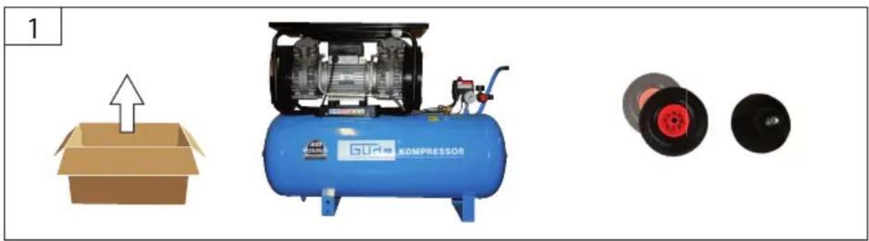
1DE Montage
GB Assembly
FR Montage
IT Montaggio
NL Montage
CZ Montáž
SK Montáž
HU Szerelés
SI Montaža
HR Montaža
BG Монтаж
RO Montaj
BA Montaža
Typ 480/10/90
natural_image
Product diagram showing a blue industrial air compressor with a cardboard box and two spools of thread (no text or symbols)
text_image
2 GHPK KOMPRESSOR 6 5 4 7 8 3 7DE Montage
SI Montaža
GB Assembly
HR Montaža
FR Montage
BG Монтаж
IT Montaggio
RO Montaj
NL Montage
BA Montaža
CZ Montáž
SK Montáž
HU Szerelés

20 kg
Typ 350/10/25
1
natural_image
Simple illustration of an open cardboard box with an upward arrow (no text or symbols)
natural_image
Blue industrial air compressor with visible propeller and motor (no text or symbols)
2
natural_image
Blue industrial air compressor unit with visible propeller and motor (no text or symbols)
text_image
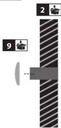
2 9| 2 | DE InbetriebnahmeGB Starting-up the machineFR mise en serviceIT Messa in funzioneNL InbedrijfstellingCZ Uvedení do provozuSK Uvedenie do prevádzkyHU Üzembe helyezés | SI Uvedba v pogonHR Puštanje u radBG Пускане в действиеRO Punerea în funcțiuneBA Puštanje u rad |

text_image
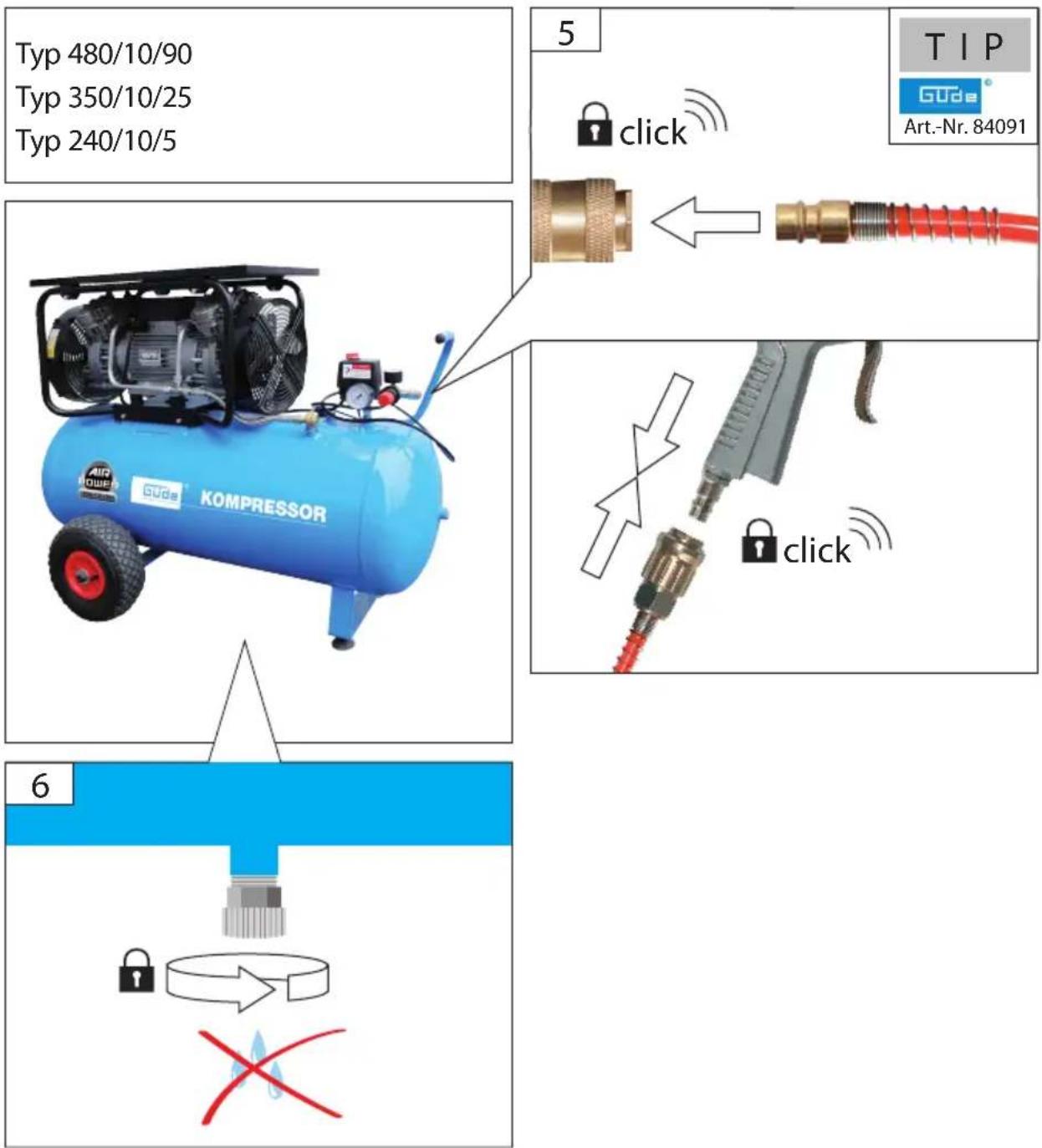
Typ 480/10/90 Typ 350/10/25 Typ 240/10/5 5 click TIP Gube Art.-Nr. 84091 AIR POWER KOMPRESSOR 6 clickDE Inbetriebnahme
GB Starting-up the machine
FR mise en service
IT Messa in funzione
NL Inbedrijfstelling
CZ Uvedení do provozu
SK Uvedenie do prevádzky
HU Üzembe helyezés
SI Uvedba v pogon
HR Puštanje u rad
BG Пускане в действие
RO Punerea în funcțiune
BA Puštanje u rad
2
TIP
A
natural_image
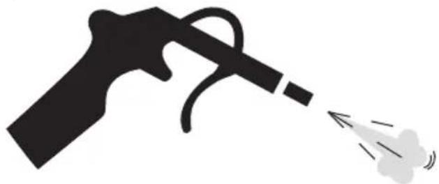
Silhouette of a spray gun emitting a spray bottle (no text or symbols)
B
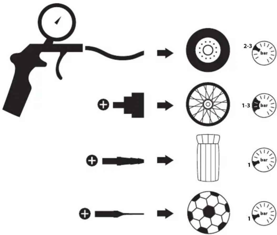
flowchart
graph TD
    A["Gun Injection"] --> B["Initial Pressure Gauge"]
    B --> C["Add Fuel Pump"]
    C --> D["Add Fuel Pump"]
    D --> E["Add Fuel Pump"]
    E --> F["Add Fuel Pump"]
    F --> G["Add Fuel Pump"]
    G --> H["Add Fuel Pump"]
    H --> I["Add Fuel Pump"]
    I --> J["Add Fuel Pump"]
    J --> K["Add Fuel Pump"]
    K --> L["Add Fuel Pump"]
    L --> M["Add Fuel Pump"]
    M --> N["Add Fuel Pump"]
    N --> O["Add Fuel Pump"]
    O --> P["Add Fuel Pump"]
    P --> Q["Add Fuel Pump"]
    Q --> R["Add Fuel Pump"]
    R --> S["Add Fuel Pump"]
    S --> T["Add Fuel Pump"]
    T --> U["Add Fuel Pump"]
    U --> V["Add Fuel Pump"]
    V --> W["Add Fuel Pump"]
    W --> X["Add Fuel Pump"]
    X --> Y["Add Fuel Pump"]
    Y --> Z["Add Fuel Pump"]
| 3 | DE | Betrieb - START | SI | Delovanje - START |
| GB | Operation - START | HR | Rad - START | |
| FR | Fonctionnement - START | BG | Páboṭa - START | |
| IT | Esercizio - START | RO | Funcționare - START | |
| NL | Gebruik - START | BA | Rad - START | |
| CZ | Provoz - START | |||
| SK | Prevádzka - START | |||
| HU | Üzemeltetés - START |

text_image
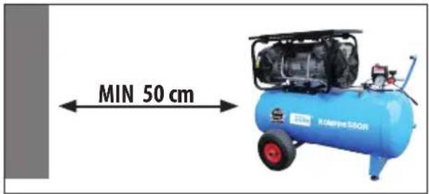
MIN 50 cm KOMPHESSOR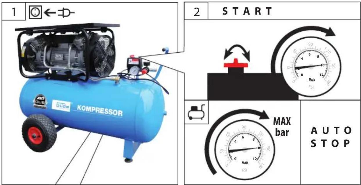
text_image
1 ← 2 START MAX bar AUTO STOP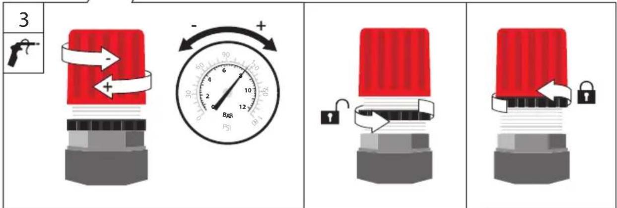
text_image
3 + - + 60 4 8 10 2 12 BMP PSIDE Betrieb-START
GB Operation-START
text_image
START 3 STOP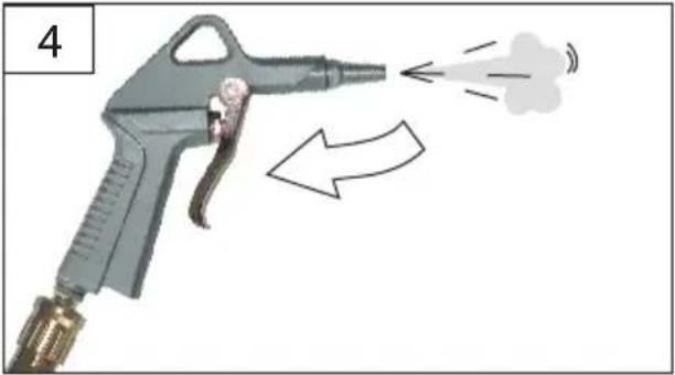
natural_image
Illustration of a spray gun emitting smoke with motion arrows indicating airflow (no text or symbols)
text_image
BARR PSI
AUTO START
MAX bar
$$ 4 8 0 / 1 0 / 9 0 = 1 0 \text { bar } \quad 3 5 0 / 1 0 / 2 5 = 1 0 \text { bar } $$
$$ 2 4 0 / 1 0 / 5 = 1 0 \mathrm{bar} $$
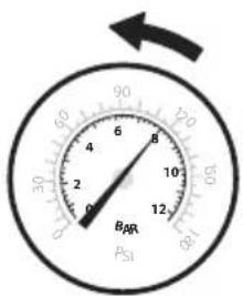
 | DE | Betrieb - STOP | SI | Delovanje - STOP |
| GB | Operation - STOP | HR | Rad - STOP | |
| FR | Fonctionnement - STOP | BG | Pábota - STOP | |
| IT | Esercizio - STOP | RO | Functionare - STOP | |
| NL | Gebruik - STOP | BA | Rad - STOP | |
| CZ | Provoz - STOP | |||
| SK | Prevádzka - STOP | |||
| HU | Üzemeltetés - STOP |

natural_image
Blue industrial air compressor with visible cooling fan and pressure gauge (no text or symbols on main body)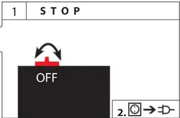
text_image
1 STOP OFF 2. ⏻→≡÷-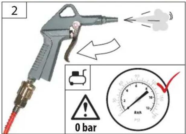
text_image
2 0 bar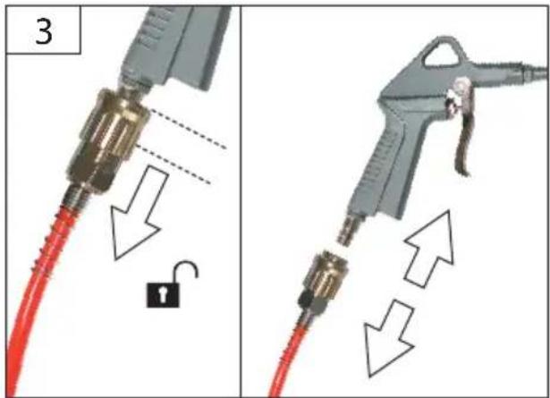
text_image
3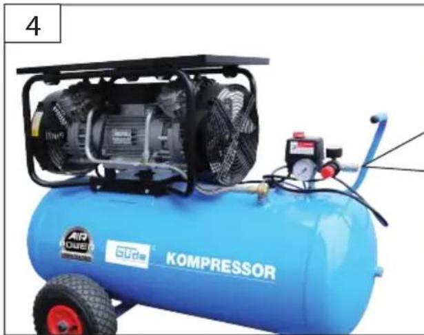
natural_image
Blue industrial air compressor with visible cooling unit and pressure gauges (no text or symbols on main body)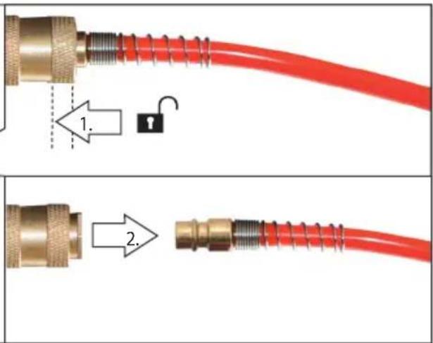
text_image
Diagram showing two stages of a red cable with a lock and connector, labeled with step numbers 1 and 2.DE Kondensat ablassen
GB Drain the condensate
FR Videz le condensat
IT Scaricare la condensa
NL Condens aftappen
GB After approx. 2-4 hours of use, the condensate that has formed must be drained from the receiver.
natural_image
Blue industrial pressure vessel with visible branding and mounting base (no readable text or symbols beyond branding)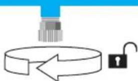
natural_image
Diagram showing a robotic arm interacting with a circular object and a padlock (no text or symbols)3
natural_image
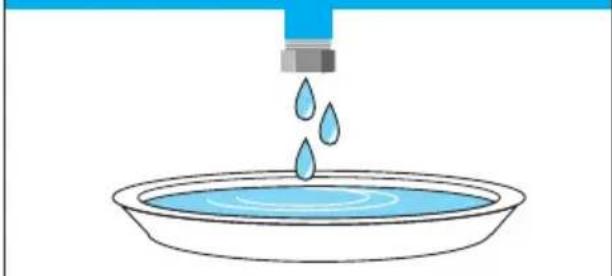
Illustration of a blue water droplet falling into a bowl of liquid (no text or symbols)4
natural_image
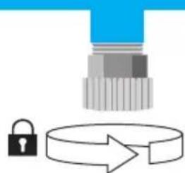
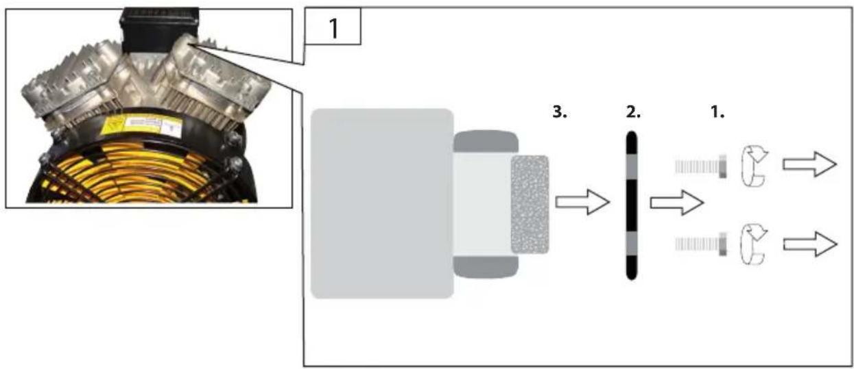
Illustration of a robotic arm interacting with a lock and directional arrow (no text or symbols)| 4 | DE Wartung-Luftfi Iter | SI Održavanje-Zračni fi ltar |
| GB Maintenance-Air fi Iter | HR Поддръжка-Въздушен филтър | |
| FR Entretien-Filtre à air | BG Întreținere-Filtru de aer | |
| IT Manutenzione-Filtro d’aria | RO Održavanje-Zračni fi ltar | |
| NL Onderhoud-Luchtfi Iter | BA Održavanje-Svijeća za paljenje | |
| CZ Údržba-Vzduchový fi ltr | ||
| SK Údrzba-Vzduchový fi Iter | ||
| HU Karbantartás-Levegőszűrő |

flowchart
graph LR
    A["Engine Component"] --> B["Assembly Step 1"]
    B --> C["Internal Structure"]
    C --> D["Product Output"]
    style A fill:#f9f,stroke:#333
    style B fill:#ccf,stroke:#333
    style C fill:#cfc,stroke:#333
    style D fill:#fcc,stroke:#333
text_image
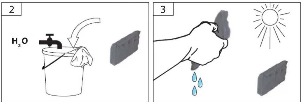
2 H₂O 3
flowchart
graph LR
    A["Stage 1: Initial State"] --> B["Intermediate Stage"]
    B --> C["Final Stage"]
    style A fill:#ccc,stroke:#333
    style B fill:#999,stroke:#333
    style C fill:#ccc,stroke:#333
GB Check valve inspection
text_image
BAR 12-7 P 51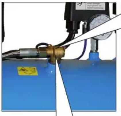
natural_image
Close-up of a blue fluid tank with a pressure regulator and pipe connection (no visible text or symbols)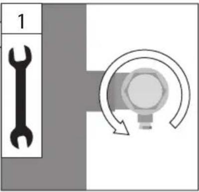
text_image
1 1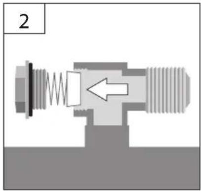
natural_image
Cross-sectional diagram of a mechanical valve or fitting with internal spring and threaded shaft (no text or symbols)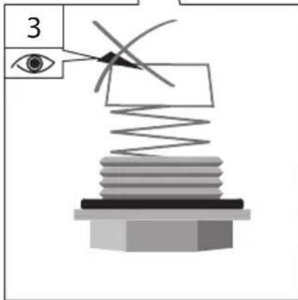
text_image
3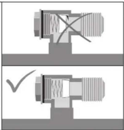
natural_image
Mechanical valve assembly diagram showing two cross-sectional views with no text or symbols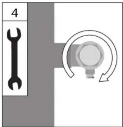
text_image
4 4Technische Daten
*Measured according to 2005/88/EC


Read and understand the operating instructions before using the appliance. Abide by all the safety measures stated in the
service manual. Act responsibly toward third parties. In case of any doubts about connection and operation refer please to our customer center Preserve all the documentation so that anyone who uses the compressor can consult this beforehand.
Specifi ed Conditions Of Use
The compressor can only be used for the production of compressed air to be used at home and by handymen. – Respecting technical data and safety precautions.

The compressed air produced by the pressor cannot not be used for pharmaceuti- food or medical purposes or to fill the air tles of scuba divers.

The compressor must be used in a suitable environment (well ventilated with an ambient temperature of between +5°C and +40°C) and cover in places with dust, acids, vapors, explosive, and ammable gases.
Do not use this product in any other way as stated for normal use. Not observing general regulations in force and instructions from this manual does not make the manufacturer liable for damages.
Safety instructions

WARNING! Electric shock! There is a risk of injury caused by electric shock!

Operation is only allowed with a safety tch against stray current (RCD max. stray rent of 30mA).
Check the voltage. Technical data given on the type label must correspond with electric network voltage.
Insert the plug of the electrical cable in a socket of suitable shape, voltage and frequency complying with current regulations.
Use extension cables with a maximum length of 5 meters and with a cable cross-section of not less than 1.5 mm ^2 . Use of extension cables of different length and cross-section and also of adapters and multiple sockets should be avoided.
Check the cable and/or socket for damages before the appliance putting into operation.
To avoid danger, a damaged mains supply pipe must be replaced by the manufacturer. Do not under any circumstances attempt any repair yourself.
Never let the compressor come into contact with water or other liquids and never direct the jet of liquids sprayed by tools connected to the compressor towards the compressor: as the appliance is live, this could cause electrocution or short-circuits.
Never use the appliance with bare feet or wet hands or feet.
Never yank the power cable to disconnect the plug from the power outlet or to move the compressor.
Warning: the compressor may restart when power is restored following a blackout.
Compressed air is a potentially dangerous form of energy; always take great care when using the compressor and its accessories.
This device is not intended for use by persons (including children) with limited physical, sensory or mental capabilities or without the necessary lack experience or knowledge unless they are supervised by a person who is responsible for their safety or were instructed by that person in how to use the device.
Children should be supervised to ensure that they do not play with the device. Always keep children and unauthorised persons out of reach of the appliance.
Never use the compressor without being supervised.
Never direct the jet of air towards persons, animals or your body.
Never keep the air flow in body holes as that could lead to fatal injuries!
Keep the work area free.
When operating, the compressor must be placed on a stable surface.
Caution! The compressor may only be used with appropriate wheels and rubber bumps.
Safety goggles should be worn when using the compressor in order to protect the eyes against any foreign bodies lifted by the jet of air.
If possible, when using air-powered accessories, wear safety clothing.
Always maintain a safety distance of at least 4 meters between the compressor and the work area.
Caution! The pneumatic hose may lash you when the quick-acting coupling is opened! The pneumatic hose should be held by hand.
Always use the handle to move the compressor.
When using compressed air, you must know and comply with the safety precautions to be adopted for each type of application (inflation, airpowered tools, painting, washing with water-based detergents only, clinching, etc.).
When using compressed air, you must know and comply with the safety precautions to be adopted for each type of application (inflation, airpowered tools, painting, washing with water-based detergents only, clinching, etc.).
Caution! Never switch the compressor on or off using the plug. Pressure switch to be pressed at all times.
Do not leave the compressor on over night as it could become a source of danger.
At the end of your working day, switch the appliance off, release the air jet and unplug the compressor.
Warning: if the water that condenses is not drained, it may corrode the receiver, reducing its capacity and impairing safety.
Never leave the appliance exposed to adverse weather conditions (rain, sun, fog, snow).
If this compressor is used outdoors, always remember to stow it after use in a covered or closed place.
Never use the compressor outdoors in rain or bad weather.
Do not place fl ammable or nylon/fabric objects close to and/or on the compressor.
Do not cover the air inlets on the compressor.
The compressor must not be fitted in a vehicle for industrial purposes without an inspection by an expert!
If the compressor is used for industrial purposes, it must be checked by an expert before putting into operation for the first time. Such check must be ordered by the operator (under BetrSichV Section 17 No. 25 – operation safety regulation)
Caution! When fitted in automatic equipment, it is necessary to install appropriate alarm or warning devices in case of power outage or malfunction or compressor (e.g. feed line, etc.) failure.
Operation at lower temperatures
At lower temperatures, below 5^ C, problems may be experienced when starting. They are manifested by growling of the electric motor. In such a case, the appliance must be immediately switched off and oil (5W30) changed in warmer conditions.
To guarantee perfect and reliable operation of the rotary and percussive pneumatic tools such as impact wrenches, staplers or nailers, etc., the compressed air must be supplied if Itered - with oil via the lubricator or maintenance unit. Tip 41086
A fi Itered water separator should be used for varnishing in any case. Tip 41089
To select a suitable pneumatic tool, the tool air consumption and the compressor eff ective amount delivered must necessarily be considered.
(Pneumatic tools and accessory equipment can be found at www.guede.com)
Requirements for operating staff
The operating staff must carefully read the Operating Instructions before using the appliance.
Qualification: Apart from the detailed instructions by a professional, no special qualification is necessary for appliance using.
Minimum age: Persons over 16 years of age can only work on the appliance. An exception includes youngsters trained in order to reach knowledge under supervision of the trainer during occupational education.
Training: Using the appliance only requires corresponding training by a professional or the Operating Instructions. No special training is necessary.
Emergency procedure
Conduct a fi rst-aid procedure adequate to the injury and summon qualifi ed medical attendance as quickly as possible. Protect the injured person from further harm and calm them down. For the sake of eventual accident, in accordance with DIN 13164, a workplace has to be fitted with a fi rst-aid kit. It is essential to replace any used material in the fi rst-aid kit immediately after it has been used. If you seek help, state the following pieces of information:
- Accident site
- Accident type
- Number of injured persons
- Injury type(s)
Maintenance
Before carrying out any work on the machine, disconnect the plug from the socket.
Run the accessory connected dry until there is no more air in the receiver.
Prior to every use, visually check the machine to rule out any defects, in particular on the power cable and the plug.
Safety valve Functional check
The machine must not be used under any circumstances if the machine or the safety devices are damaged.
Use only original accessories and original spare parts.
Never clean the machine and its components with solvents, flammable or toxic liquids. Us only a damp cloth making.

Oil-free
to add oil for operation
Only a regularly maintained and treated appliance can serve as a satisfactory aid. Insufficient maintenance and care can lead to unforeseen accidents and injuries.
If necessary, a list of spare parts can be found at www.guede.com.
Guarantee
Warranty period of 12 months applies to commercial use and 24 months applies to private use and commences on the day of purchase of the device.
The guarantee solely covers inadequacies caused by material defect or manufacturing defect. Original payment voucher with the sales date needs to be submitted for any claim in the guarantee period.
The guarantee does not cover any unauthorised use such as appliance overloading, use of violence, damage as a result of any unauthorised interference
or caused by foreign items. Failing to follow the operating and assembly instructions and common wear are also not included in the guarantee.
Service
Do you have any technical questions? Any claim? Do you need any spare parts or operating instructions? We will quickly help you and without needles bureaucracy at our web pages at www.guede.com in the Servicing part. Please help us be able to help you. In order to identify your device in case of claim we need the serial No., product No. and year of production. All this data can be found on the type label. Please enter it here for future reference:
Serial No.:
Art. No:
Year of production:
Symbols

Read the Operating Instructions!

Before carrying out any work on the machine, disconnect the plug from the socket.

Wear eye protective goggles! Wear ear protectors!

Protect against humidity Never expose tool to rain.

Cable pulling / transport prohibited

Warning/caution!

Dangerous voltage

Caution - hot surface! Warning, hot surfaces!

Danger - automatic control (closed loop)

Warning against thrown-off items

Keep distance of persons! Observe to keep out of dangerous zone

Any damaged or disposed electric or electronic devices must be delivered to appropriate collection centres.

Protect against humidity

This side up
Failure removal
| Defect Causes Measure | ||
| Compressor not starting after being switched on | Pressure in the air jet exceeds the closing pressure | Release the pressure in the air jet so that the pressure switch gets automatically switched on |
| Defective supply Have the current supply checked by an authorised person | ||
| Defective pressure switch Have the pressure switch replaced by an authorised person (Güde service centre) | ||
| Worn carbons Replace the carbons | ||
| After reaching the closed pressure, the compressor runs or buzzes for a short time and then switches off automatically | Electric cable is too long or its cross section is too small | Check the length and cross section of the electric cable |
| Compressor running constantly | Suction filter is very dirty | Clean or replace the suction filter |
| Pneumatic tools have high air consumption | Check the pneumatic tool air consumption; seek an authorised compressed air dealer | |
| Leaking on the compressor Localise the leaking, contact the Güde service centre | ||
| Compressed-air pipeline leaking Contact the Güde service centre | ||
| Drain valve is open or missing Close or insert the drain valve | ||
| Compressed air is released from the discharge valve under the pressure switch when the appliance is being operated | Discharge valve is defective Discharge valve renew | |
| Check valve insert is leaking or defective | Clean or replace the check valve insert → [1] | |
| After reaching the cut-off pressure, air is released from the discharge valve under the pressure switch until the closing pressure is reached | Check valve is damaged | Replace the check valve |
| Compressor gets started too often | Too much condensate in the air jet | Drain the condensate |
| Compressor is overloaded | ||
| Safety valve blowing off | Pressure in the air jet exceeds the set cut-off pressure | Have the pressure switch adjusted/replaced by an authorised person (Güde service centre) |
| Safety valve is defective | Replace the safety valve or contact the Güde service centre | |
| Compressor getting warm too much | Air supply is not sufficient | Make sure sufficient air supply and outlet (minimum distance from wall is 40 cm) is provided |
| Cooling fi ns on the cylinder (cylinder head) are dirty | Clean the cooling fi ns on the cylinder (cylinder head) | |
| Too long time of appliance operation | Switch the compressor off | |
| Compressor being overheated and keeps switching off | Compressor is overloaded | Contact the Güde service centre |
| Compressor is defective | Contact the Güde service centre | |
| Compressor under undervoltage Contact the Güde service centre | ||
| Outdoor temperature of 35°C | ||
Do you have any technical questions? Any claim? Do you need any spare parts or operating instructions? We will quickly help you and without needles bureaucracy at our web pages at www.guede.com in the Servicing part. Please help us be able to help you. In order to identify your device in case of claim we need the serial No., product No. and year of production. All this data can be found on the type label. Please enter it here for future reference:
Numéro de série:
Numéro de commande:
Do you have any technical questions? Any claim? Do you need any spare parts or operating instructions? We will quickly help you and without needles bureaucracy at our web pages at www.guede.com in the Servicing part. Please help us be able to help you. In order to identify your device in case of claim we need the serial No., product No. and year of production. All this data can be found on the type label. Please enter it here for future reference:
Sériové číslo:
Objednací číslo:
Rok výroby:
Symboly

EC-Declaration of Conformity
We, hereby declare the conception and construction of the below mentioned appliances correspond - at the type of construction being launched - to appropriate basic safety and hygienic requirements of EC Directives.
In case of any change to the appliance not discussed with us the Declaration expires.
2006/42 EG 2006/42 EG 2006/42 EG
2004/108 EG 2004/108 EG 2004/108 EG
2009/105 EG 2009/105 EG 2009/105 EG
2000/14 EG 2000/14 EG 2000/14 EG