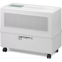
B 500 - Humidifier TROTEC - Free user manual and instructions
Find the device manual for free B 500 TROTEC in PDF.


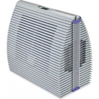
| Product type | Evaporative air humidifier |
| Brand | Trotec |
| Model | B 500 Professional |
| Dimensions (L x H x D) | 75.5 x 62 x 36.5 cm |
| Weight (empty) | 24 kg |
| Power supply | 230 V / 50 Hz, max. power consumption 95 VA (without accessories) |
| Evaporation capacity | 2.6 L/h at 25 °C and 20% RH |
| Tank volume | 50 liters (max.) |
| Air flow (ventilation) | 900 m³/h |
| Filter surface area | 3.5 m² |
| Filter type | Biological filter (ref. 1603) or honeycomb filter (ref. 1601), optional activated carbon set |
| Settings | Integrated hygrostat, infrared remote control, menu programming |
| Main functions | Automatic humidity regulation, 5 ventilation levels (4 manual + automatic), water level and filter change indicator |
| Maintenance and cleaning | Cleaning of copper electrodes, filter replacement every 56 to 98 days, draining and cleaning the tank every 3-4 weeks, annual descaling |
| Safety | Automatic shut-off when tank empty, error code indicator, 2 AT fuse, disconnection recommended before any intervention |
| Spare parts and repairability | Filters, water pump, fan, control panel, UV lamp (optional), remote control, radio-electrical sensor |
| Optional accessories | Automatic water supply, rinsing device, UV technology with lime conversion cartridge, air recovery hood |
| General information | Instruction manual available in several languages; remote control with AAA batteries; radio-electrical sensor 435 MHz |
Frequently Asked Questions - B 500 TROTEC
User questions about B 500 TROTEC
0 question about this device. Answer the ones you know or ask your own.
Ask a new question about this device
Download the instructions for your Humidifier in PDF format for free! Find your manual B 500 - TROTEC and take your electronic device back in hand. On this page are published all the documents necessary for the use of your device. B 500 by TROTEC.
USER MANUAL B 500 TROTEC
Inhalt
19. Reinigung
- Commissioning B - 02
Commissioning Check List ....B - 02
-
Location B - 02
-
Power consumption B - 02
-
Atmospheric humidity B - 02
-
Control panel at a glance....B - 03
-
Remote control B - 03
-
Filling B - 04
-
Water level indicator B - 04
-
Filter change indicator B - 04
Changing the filter ....B - 05
-
Changing the control panel ..... B - 06
-
Connections on the circuit board.....B - 06
-
Fan settings B - 07
Changing the fan . . . . . . . . . . . . . . . . . . . . . . . . . . B - 07
- Radio-sensor-system B - 07
Starting up....B-07
- Coding the radio-sensor-system ..... B - 07
Coding the sensor.....B - 07
Procedure....B - 08
-
Fault code display . . . . . . . . . . . . . . B - 08
-
Menu programming . . . . . . . . . . . . . B - 09
-
Water pump B - 11
-
Hygiene products B - 11
-
Cleaning B - 12
-
Accessoires..... B - 12
Automatic water supply ...... B - 12
Automatic rinsing system ....B - 13
Activated charcoal cleaning filter ..... B - 13
Air scoop with flexible hose ...... B - 13
UV-technology with calcium
conversion cartridge....B - 14
Changing the UV-tubes.....B - 14
-
Parts list B - 15
-
Design/ Exploded-view drawing ..... B - 16
-
Maintenance check lists B - 17
-
Correcting faults B - 19
-
Installation suggestions..... B - 20
-
Technical data. B - 21
This publication replaces all previous announcements. No part of this publication may be reproduced, processed using electronic systems, replicated or distributed in any form, without our written authorisation. Subject to technical changes. All rights reserved. Names of goods are used without guarantee of free usage keeping to the manufacturer's syntax. The names of goods used are registered and should be considered as such. We reserve the right to modify design in the interest of on-going product improvement, such as shape and colour modifications. The scope of delivery may vary from that in the product description. All due care has been taken in compiling this document. We accept no liability for errors or omissions. © TROTEC®
01. Commissioning
⚠ Before you commission your new equipment, please read through the operating instructions!
Commissioning Check List
- Within the equipment are the accessories: mains plug, radio sensor system, remote control.
- Remove the upper part, withdraw parts and close the equipment cover again.
- Install batteries of the remote control and the radio sensor.
- Check radio sensor system for functionality. Briefly illuminate the diode by pressing the black knob. A warning tone indicates that the batteries must be replaced. When changing the batteries mind the +/- poles.
- Fill device with tap water. Observe the light emitting diodes of the water level fill indicator. Max. 50 litres – do not overfill!
- Enter desired values with the infrared remot control (Air humidity, blower stage). Wait 10 seconds until the storage process is finished.
02. Location
The humidifier should be placed on an even surface. This facilitates circulation and it is advantageous if the heat source (convector or similar) is located nearby. Avoid subjecting the humidifier to the effects of outside temperatures in excess of +70°C.
03. Power Consumption
The humidifier is connected to a 230V AC, 50 Hz socket outlet. The power consumption rating is max. 150 VA. It is advisable to protect the electrical supply line with a 10 Amp fuse. For safety reasons, the power plug must be disconnected when carrying out all work on the humidifier.
04. Humidity
The electronic hygrostat (radio-sensor-system) automatically controls the humidifier. The required humidity values can be set by means of the remote control.
⚠ Disconnect the mains plug before opening the equipment!
05. Control panel at a glance
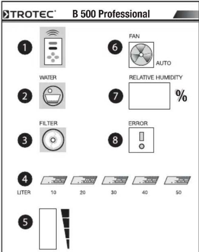
1 Receiver sensor for remote control
2 Empty water tank indicator
3 Filter change indicator
4 Electronic water level indicator
5 Fan speed indicator
6 Automatic fan
7 Actual/required atmospheric humidity display, Menu in programming mode or Fault code with error message
8 Error message display (note fault code)
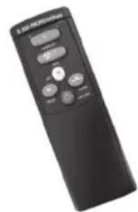
- Remote Control
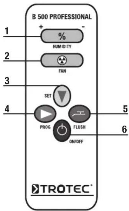
1 Humidity button
The required humidity value can be set with this button. Pressing + or - several times or holding it down alters the humidity setting upwards or downwards.
2 Fan Taste
Pressing + or - several times increases or de-creases the fan speed. Other fan speeds can be selected with the „Automatic” setting (4).
3 SET button
With the Set button you can select from the sub-men-us Taste (21, 22, 23) in programming mode. If no other settings are made, after 10 seconds the display automatically jumps back to the standard display figure, i.e. indoor atmospheric humidity. Changes that have been made to the required humidity setting or in programming mode are saved.
4 PROG button
Pressing this button opens the programming mode of the B 500 so that you can select from the main menus (10, 20, and 30). See page 9 for a description of the menus.
5 Flush button
Pressing this button activates the rinsing system. (optional extra)
6 ON/OFF-Taste
The appliance can be switched on or off by pressing this button.
⚠️ Supplied with two 24G Size AAA 1.5V batteries.Please do not use any other type!
07. Filling
(not applicable for humidifiers with automatic water supply)
The device is filled with water via the upper filler flap using a watering can (only up to the max. level mark, 50 litres). The water level is indicated by light emitting diodes (max. 5 stages). Both normal tap water and softened water can be used to operate the humidifier.
Do not use distilled water! Take care to fill correctly, since spilt water could enter the equipment and cause a short circuit. The maximum temperature of the water must not exceed 35 °C.
08. Water level indicator
The water level is sensed by copper electrodes and is indicated by LEDs on the control panel. The device switches off automatically if the red „Top up water“ LED comes on. A small quantity of water always remains in the tank (approx. 15 litres). It is advisable to regularly (approx. every 3-4 weeks) drain off the residual water depending on the degree of soiling
and calcium (lime) content. The opportunity should be taken to clean the water tank with a sponge or a wet vacuum cleaner. The electrode rods require occasional cleaning to ensure they do not indicate incorrect values or cause the humidifier to shut down owing to calcification of the voltage electrodes. Distilled water must not be used because it leads to malfunctions in the water level indicator.
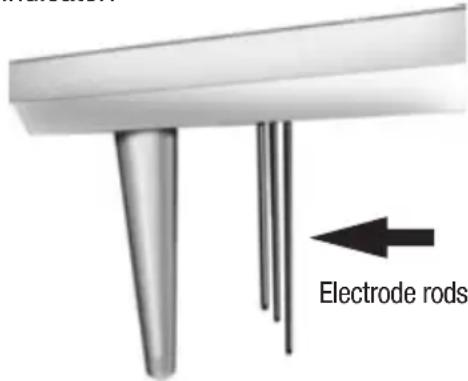
09. Filter change indicator
The B 500 atmospheric humidifier has a filter change indicator. The frequency with which the filter needs to be changed depends on the length of time for which the pump runs, the hardness of the water, and the fan. Under the best circumstances it will have to be changed after 98 days, in the worst after 56 days, but this is only a recommendation; the situation can be affected one way or the other by such external factors as air pollution or the hardness of the water. In any case it is advisable to make regular visual checks of the filter Please see the section on „Changing the filter” for detailed instructions. When you have changed the filter you have to reset the indicator manually to its initial position. Please proceed as described in the section on „Menu programming“ to Menu 33, where you can reset the filter change indicator at any time to its initial position of 98 days.
Filter change
Depending on the operating time of the humidifier, the special filter is used up during the course of time as a result of mineral deposits in the water and dust deposits in the air (every 8-16 weeks depending on the water hardness, dust accumulation and operating time). The filter should not be washed as this reduces the evaporation capacity of the device. All humidifi-
ers are equipped with a BIO filter (Order No. 1603) as standard (high evaporation capacity). Foam filters (Order No. 1601) are also still available. In addition, we also offer a special activated charcoal cleaning filter in a 2-pack (Order No. 1605).
In order to ensure perfect operation, only use Original Replacement Filters and Original Replacement Parts. We undertake no responsibility or warranty for any water damage or reductions in performance.
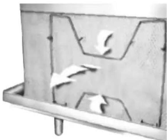
- Remove the two clips by pressing them together.
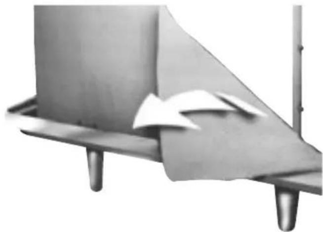
- Release filter from 4 retaining lugs.
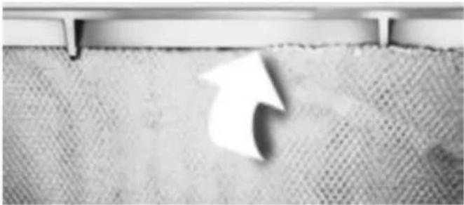
- Fit new filter in reverse order, secure clips and make sure that the filter rests within the bottom U-shaped rail over the entire length of the water distribution.
⚠️ Particular care must be taken to ensure the two side clips are fitted correctly otherwise the filter may make contact with the upper section of the housing, thus causing leaks.
10. Changing the control panel
⚠ Before doing any work on the appliance, always make sure it is unplugged from the wall socket!
In the event of a defect in the control panel it may be necessary to replace it completely.
Please proceed as follows.
- Raise the upper part of the housing.
- Loosen the four screws on the corners of the control panel and take the panel out.
- Unplug the plugs ①,②, X9) vfrom the circuit board and if necessary also unplug the plugs 3-5.
- Use a small screwdriver to loosen the screws of the central power connection XI and pull the cable out of the clamp.
- Loosen any other connections. (X3, X2)
- You can now pull out the circuit board completely.
- Now attach the individual connection to the new circuit board in the reverse order. Note the numbers on the plugs and the circuit board when making the plug-in connections.
- Insert the control panel back into the shaft and fasten it with the four screws.
- Now replace the upper part of the housing back onto the B 500.
The appliance is protected by a conventional fuse with the rating of 2 AT.
11. Connections on the circuit board
Connection Description Power supply Power
consumption
X1 Power supply 230V AC (L, N, and 6 x PE) 230V 50Hz 200 VA
X2 Zero-potential malfunction reporting relay 42V 1A
X3 External water sensor (zero current) - -
1 Fan connection 230V AC 230V 50Hz 65 VA
2 Water pump 230V AC 230V 50Hz 25 VA
3 Rinsing pump 230V AC 230V 50Hz 25 VA
4 Magnetic valve 230V AC 230V 50Hz 10 VA
5 UV lamp 230V AC 230V 50Hz 6 VA
X9 Water sensors, 10 litre to 50 litre - -
12. Fan settings
The fan can be set by the remote control unit at any of five speeds (4 set speeds and one automatic function). The required speed can be set with the Fan button (see above) on the remote-control unit. When the Fan button is pressed the bar indicator starts to flash. Pressing the + or the - side increases or decreases the fan output. The automatic function enables the appliance to control its own speed depending on the output required. It does this by measuring the changes in atmospheric humidity and increasing or decreasing the fan speed accordingly. To activate the automatic fan, press the „-” side of the Fan button and hold it down until the last bar has disappeared from the indicator and the red diode with the fan symbol has gone out. To deactivate it, simply increase the fan speed with the Fan button until the red diode comes on again.
Changing the fan
⚠️ Before doing any work on the appliance, always make sure it is unplugged from the wall socket.
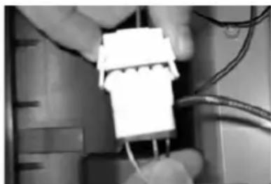
- Loosen and pull the fan plug by pressing the plug clamps.
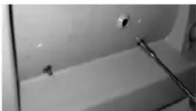
- Set the centre part of the B 500 aside and loosen
the three boltings. Mind that the fan does not fall out after the screws are loosened.
- Take the fan out.
-
Insert the new fan and attach the screw threads to the vibration absorber by plugging them through the holes in the centre
-
Tighten the fan and plug the appliance in again.
13. Radio-sensor-system (Radio frequency 435 MHz)
Starting up
Carefully loosen the underneath of the housing, e.g. with a screwdriver. Replace the batteries (MN 1500 LR6, 1,5 V AA).
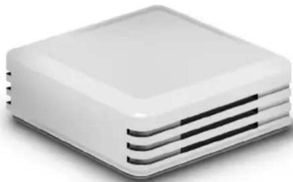
⚠ Make sure the poles (+/-) are inserted correctly.
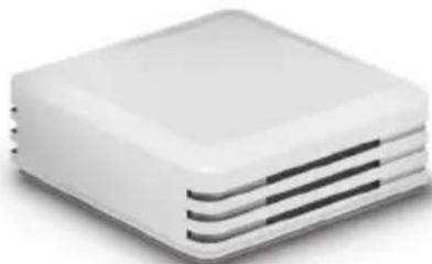
Press the small black test knob ① to check the transmission function (the green test diode ② should light up). Please attach it to a dry, well ventilated place such as a ceiling or a wall and make quite sure it is not exposed to any direct sunlight. (The calibration is factoryadjusted to 2%)
14. Coding the radio sensor system
Coding the sensor
These appliances are coded in the factory, but if two or more are used in direct proximity to one another (i.e. less than 50 metres apart) a different coding may be necessary.
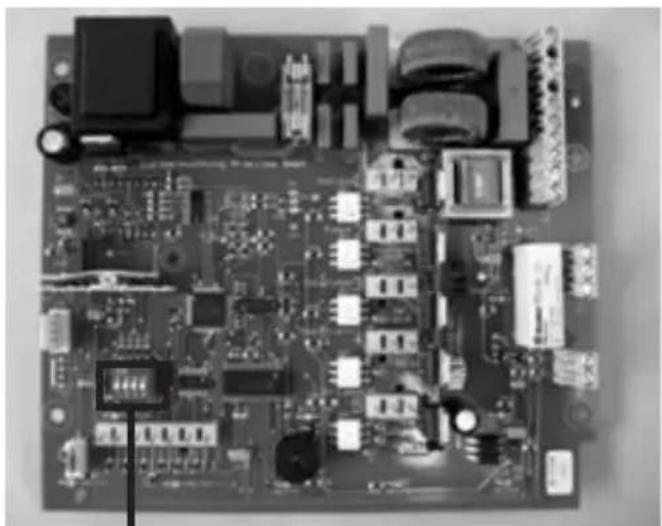
a) Device circuit board B 500
b) Radio sensor circuit board
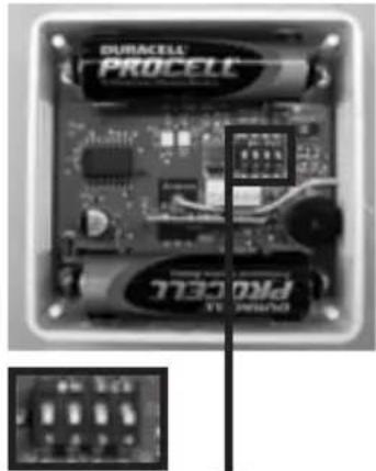
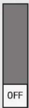
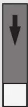

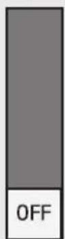
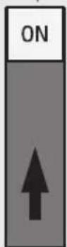
For each slide control there are only two positions: „ON“ = up and „OFF“ = down, which give 16 possible combinations. Please note: each appliance and its radio sensor (a + b) must have the same coding.
You have the option here of controlling a number of appliances in one room from one sensor, with all of them
identically coded to the one sensor, or of operating each one independently, each with a separate sensor and different codings. Please proceed as follows.
Procedure:
- Carefully lift the cover of the radio sensor with a small screwdriver and take it off.
- Code the radio sensor by setting the slide control with a small screwdriver.
- Remove the housing of the B 500 air humidifier.
- Loosen the four of screws on the top side of the control panel and lift it off.
- Code the receiver circuit board on the rear side of the control panel by setting the slide control with a small screwdriver.
The coding of the radio sensor and of the receiver circuit board must match exactly (note ON and OFF). Otherwise there is no certainty that the system will function.
- Close the cover of the radio sensor again.
- Fasten the control panel down again with the four screws and set the top part of the housing onto it.
- Breathe lightly on the radio sensor to check the functioning of the system
15. Fault code display
The B 500 Professional has an independent monitoring system that gives you the possibility of spotting errors quickly and reacting accordingly.
The fault display can be combined with an acoustic signal so that a „beep” can be heard in addition to the display being shown. You can select this setting yourself. Please refer to the section on „Menu programming”.
The following fault codes tell you what problem has occurred and what has to be done.
⚠️ If a fault code is displayed, only the On/Off button and the PROG and SET key on the remote control unit can be used.
Fault code Fault What to do?
| 01 Water tank is empty • Check water level and top up if necessary. | |
| • Check water level diodes for dirt and clean if necessary. | |
| • Has distilled water been used? If so, top up with plain tap water. | |
| • Check the diodes connection. | |
| • Is the automatic water supply defective? (optional extra) | |
| 02 UV lamp defective • Replace UV lamp. (see „Changing the UV tube“) | |
| 03 Water leaking(only possible with external water sensor) | • Check whether the filter has been inserted correctly. |
| • Check whether the appliance is standing upright. | |
| • Check whether the automatic water supply is working correctly (if fitted). | |
| • Check tank for leaks. | |
| 04 Water tank overfilled(only possible with automatic water supply) | • Check the function of the magnetic valve. |
| • Check the water level diodes for dirt. | |
| 05 No radio signal from hygros-tat. The receiver on the con-trol panel has not received a signal for a quite some time. | • Is the radio transmitter too far away from the appliance? |
| • Check the function and coding of the radio transmitter (see „Starting up” / „Coding the radio sensor system”). | |
| • Replace the batteries if necessary. | |
| 09 Several faults have occurred simultaneously | • Check the appliance as described for Faults 01 to 04. |
16. Menu programming
The B 500 Professional offers you the possibility of changing the factory settings and making various settings to meet your requirements.
Please proceed as follows:
- Press the „PROG“ button on the remote control unit „Prog“.
- The number „10“ will appear on the control panel display.
- Select one of the main menus (10, 20, or 30, see table below).
-
Once your have reached the main menu you are looking for, press the „SET” button to reach the required sub-menu, e.g. 11, 12, or 13.
-
Once your have reached the sub-menu you are looking for, after a few seconds the display will flash with a number such as 00, 01, or 98. By pressing the blue „Humidity“ button (%) you can increase the figure with ‘+’ or decrease it with ‘-’.
-
When you have made the necessary change, simply wait for about 10 seconds. After that the display will jump back to the standard position (showing relative humidity) and the changes will be saved.
⚠️ If no more settings have been made for 10 seconds the display will jump back to the standard position (showing relative humidity). The programming process can be terminated at any time by pressing the ON / OFF button. Please note, however, that this will result in the loss of all the changes that have been made.
| Main menu | Sub-menu | Description Setting Comment Factory | setting | |
| 10 Hooter setting | ||||
| 11 Hooter active when tank empty | 00 = OFF01 = ON | 01 | ||
| 12 Hooter active when UV lamp is defective | 00 = OFF01 = ON | Only at version with UV-C-technology 01 | ||
| 13 Hooter active with external water sensor alarm | 00 = OFF01 = ON | With external sensor | 01 | |
| 14 Hooter active when tank content >=50 liters | 00 = OFF01 = ON | (Only in combination with automatic water supply) 01 | ||
| 15 Hooter active when no radio signal | 00 = OFF01 = ON 01 | |||
| 20 Relay setting | ||||
| 21 Relay active when tank empty | 00 = OFF01 = ON | Only necessary with connection to a central air-conditioning system 00 | ||
| 22 Relay active when UV lamp is defective | 00 = OFF01 = ON | Only necessary with connection to a central air-conditioning system 00 | ||
| 23 Relay active with external water sensor alarm | 00 = OFF01 = ON | Only necessary with connection to a central air-conditioning system 00 | ||
| 24 Relay active when tank content >= 50 Litre | 00 = OFF01 = ON | Only necessary with connection to a central air-conditioning system 00 | ||
| Main menu | Sub-menu | Description Setting Comment | Factory setting |
| 25 Relay active when no radio signal | 00 = OFF01 = ON | Only necessary with connection to a central air-conditioning system 00 | |
| 26 Relay switch status(Low= Relay active open High= Relay active closed) | 00 = OFF01 = ON | Only necessary with connection to a central air-conditioning system 00 |
| Main menu | Sub-menu | Description Setting Comment Factory | setting |
| 30 Rinsing setting | |||
| 31 Rinse cycle in days 00 = OFF | (manuell)01 ... 07 days | If rinsing is existent | 07 |
| 32 Water hardness setting 01 = soft | 02 = medium03 = hard | Water hardness affects the filter change display interval | 02 |
| 33 Resetting the filter change indicator | 98 = reset The display „98 - .00” shows in how many days the filter will have to be changed. The display can be reset to 98 days at any time | 98 | |
| 34 Operation via external time switch or other 230V switching mechanism | 00 = OFF01 = ON | REQUIRED humidity level is fixed at 90%. The ACTUAL display shows a constant 00%rF. The fan can be set freely at any suitable speed | 00 |
| 35 Setting/Changing interval of the fan in auto-mode | 01 ... 10 min. | Dependent on the size of the room | |
17. Water pump
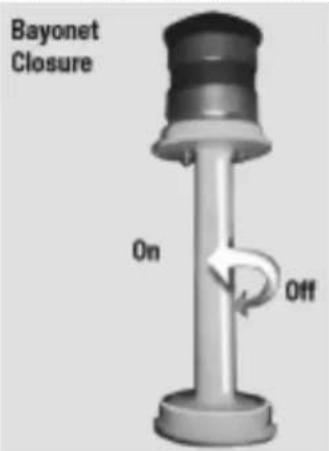
The immersion pump can be removed from the centre
plate by turning it in the direction indicated by the arrow. Take particular care when installing the pump to ensure that the plug connection as well as the pump hoses and the Y-piece, or on devices with UV-technology the connection hoses to the V4 A-pipe, are firmly fitted.
18. Hygiene products
To prevent the development of germs, algae, mould or bacteria and the odours they cause in the water container of a humidifier, we recommend the use of
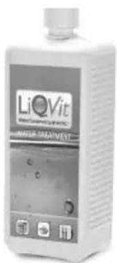
adequate hygiene products such as LiQVit and Secosan. Secosan can be placed directly in the water container. When exchanging the water in the reservoir, simply take it out and the Secosan Stick can be used again. Depending on the volume of the
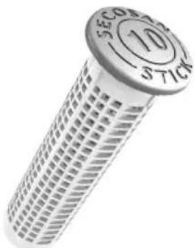
water container, there are different Secosan Products available. Like the Secosan Stick, LiQVit is also designed to keep the water in your humidifier clean and free of bacteria, algae and mould. Apart from that, it also reduces the waters' surface tension, which leads to an increased rate of dehumidification. Working against lime scale, it can also significantly increase the lifetime of the evaporation filter.

19. Cleaning
The device should be cleaned of calcium (lime) deposits and soiling every 3-4 months. For this purpose, the upper section of the housing is detached, the filter removed and the centre plate cleaned. A commercially available cleaning agent can be used for this purpose. All traces of the cleaning agent must be removed (rinse thoroughly with clean water).
⚠ Do not use benzene or other solvents that attack plastic.
The humidifier should be cleaned thoroughly once a year (preferably by our maintenance service). Use commercially available limescale remover (decalcifying agent) to remove lime residue. Then rinse thoroughly with clean water. The water distributor is open at the top, easily accessible and should be cleaned of any residue. If blocked, the drain holes in the water distributor can be cleaned with a knitting needle or similar. While cleaning, check to ensure there are no sludge deposits in the pump hoses. If necessary, they should be cleaned with a narrow bottle brush or they should be replaced. Should the equipment remain out of service for longer periods, the residual water is to be emptied out, the filter is to be removed and cleaning is to be carried out.
Automatic water supply
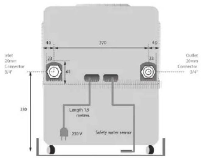
The connection to the local water main must be made by a qualified specialist, i.e. a licensed installation technician. (Please note the water supply utility's regulations. It may be advisable to fit a back-flow stop valve.) We recommend our 1.5-metre long safety pressure hose for the connection between the water pipe and the appliance (Product no 1754). The automatic system for topping up the water incorporates a magnetic valve. In the factory the appliance is set at automatic water supply at a maximum fill level of 30 litres, i.e. when the fill level reaches 30 litres the water supply is shut off. If the water supply is active, this is shown by a running light (10-50 litre diodes flash on after the other). The water supply is controlled by the electronic rods in the water level display. To ensure faultless functioning of the automatic water supply it is therefore necessary for the electrode rods to be cleaned regularly with a sponge and freed of any deposits of chalk or dirt. In order to avoid overfilling, when the fill level of 50 litres is reached a malfunction message is issued, i.e. the appliance is automatically switched off, an audible warning signal is given, and Fault Code 04 appears in the display. If the water supply is defective and the water level does not change although the magnetic valve is open, the process is terminated and Fault Code 01 appears in the display. Please refer to the next page (Rinsing system) for a sketch and the dimensions. We recommend for safety's sake that our safety collection tub (Product no. 1752) should be used, connected to our safety water sensor (Product no. 1757), or that an addition external water valve should be used (Product no. 1753).
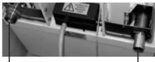
Water supply Rinsing system outlet
⚠ The maximum water pressure must not exceed 10 bar!
Automatic rinsing system
The purpose of the rinsing system is to let the residual water out of the tank at regular intervals and to let in fresh water. The rinsing system can be started manually via the remote control unit by means of the „Flush“ button or alternatively via Menu point 31, with automatic flushing intervals between 1 and 7 days. For making the setting please refer to the section on „Menu programming.
![graph TD A["Dirty water is pumped out"] --> B["Rinsing pump"] B --> C["Magnetic valve / inlet/ automatic water supply"] C --> D["Water level diodes"] D --> E["Fresh water is let in"]](/content/2026/02/404446/images/2b7170b45e6f0f1b7e8d78254f7be2b27a50465ef24a15faf4c375e3e6d6b337.jpg)
An automatic rinsing system is only possible in combination with the automatic water supply. There is then no need for any manual water exchange. The connection of the rinsing system to the local waste-water mains must be made by a specialist technician, i.e. a licensed installation technician.
When the waste-water hose is being connected it is important to make sure that it is not laid in an upward slope and that its length does not exceed 1.5 metres because the pump's capacity is not limitless and otherwise no pressure would be built up. It might therefore be necessary to fill the hose with water beforeconnecting it so that a siphon can be created.
Activated charcoal cleaning filters
The two cleaning filters can be easily removed from the clips. The service life is approx. 6 months which primarily depends on the dirt in the room air (e.g. smoke and dust accumulation).
Air scoop with flexible hose
These accessories are especially used in church organs. The scoop is fitted or screwed to the outlet of the B 500. Provided with a flexible aluminium ventilation hose (150 mm), which carries the humidified air into the critical organ area. The hygrostat must also be positioned in this area. The hygrostat controls the B 500 humidifier located on the outside in a position with good access.
(Wall mounting on brackets is also possible)
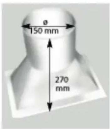
Height of scoop: 270 mm
Diameter: 150 mm
Overall height with flexible hose 570 mm
scoop
UV-technology with Calcium Conversion Cartridge
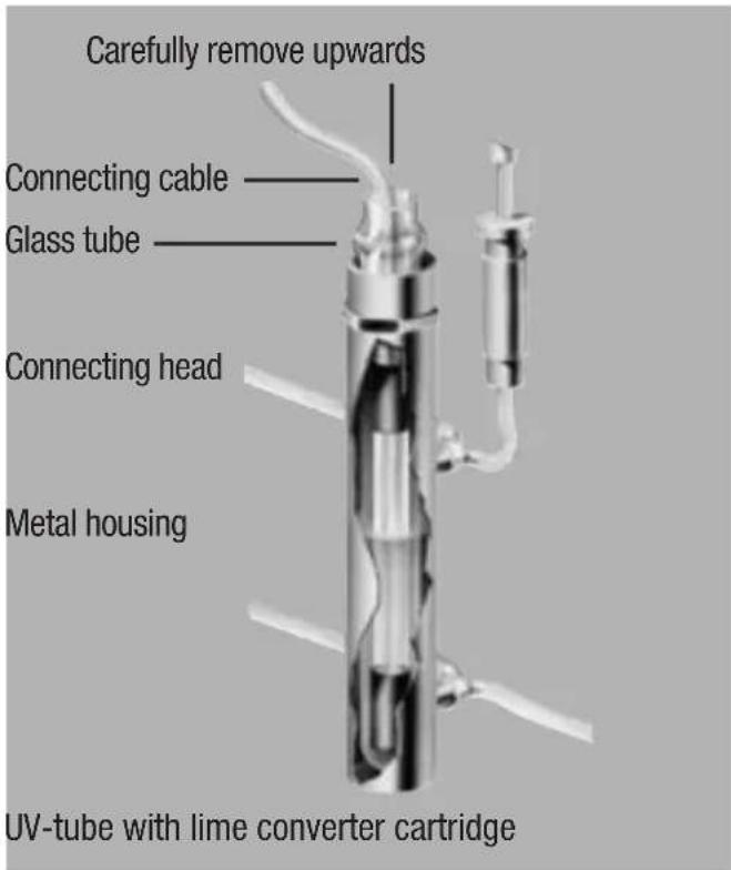
The low pressure mercury vapour lamp used in the device operates in the UV-C range in which the wavelength kills most microorganisms. The humidifier water is therefore effectively disinfected and is fed into the water circuit of the humidifier with reduced germ content. Permanent magnets produce a magnetic field, past which the humidifier water is fed. As a result, the molecular structure of the calcium is changed so that it can no longer collect on surfaces in the device. Always keep the passage in the calcium conversion cartridge clean. (see page B17)
⚠ Using softened water can lead to heavy damage to the lime transformation cartridge. It's strongly recommended to avoid the combined usage!
Changing UV-tubes
- Please first remove the switch panel as described on page 5. The UV-tube is located under the switch panel, next to the pump motor.
- Pull out the UV-tube on the connecting cable and replace the tube.
- Reattach the electrical connecting head to the UV-tube properly and insert it into the glass tube again with care.
The UV-lamp is to be disposed of in accordance with legal requirements.
The UV-tube has an operating life of about 5000 hours.
⚠️ Please take care that the quartz glass body in which the source sits is not damaged when fitting and removing the UV-source.
All accessories can be retrofitted at any time at the factory or by an authorised dealer.
In order to ensure perfect operation, only use Original Replacement Filters and Original Replacement Parts. We undertake no responsibility or warranty for any water damage or reductions in performance.
21. Parts list
1101 Housing upper section cream white
1102 Housing upper section grey
1104/500 Housing upper section anthracite
1131 Suction grid cream white (2)
1132 Suction grid grey (2)
1134 Suction grid anthracite (2)
1141 Exhaust grid cream white
1142 Exhaust grid grey
1144/500 Exhaust grid anthracite
1149 Filter replacement plate
1150 "Fill here" label
1151 Filler flap cream white
1152 Filler flap grey
1154 Filler flap anthracite
1201 Housing lower section cream white
1202 Housing lower section grey
1204/500 Housing lower section anthracite
1251 Locating cover (4)
1252 Guide pulleys (4)
1301 Centre plate cream white
1302 Centre plate grey
1304/500 Centre plate anthracite
1309 p Armature plate
1311 Shaft
1312/500 Shaft cover
1326 Electrode rods (set of 7) with head
1339 Cable loom
1347 p Base circuit board
1348/3 Measurement/transmission module complete with housing, without batteries
1348/4 Battery 1,5 V AA (2)
1350 Cover Box
1351 Tensile strain reducer
1352 Terminal block
1353 Power cable with plug
1355 Cable 0.8 m
1356 Cable 0.8 m with socket
1362 "Withdraw mains plug" plate
1369 keypad foil
1401 Water distribution
1402 Stick-on part extension (left)
1403 Stick-on part extension (right)
1406 Remote control
1411 Filter rods without grooves (6)
1412 Filter rods with grooves (4)
1413 Clamp-bracket with double-nib
1500 Fan complete with motor, housing and mounting parts
1507 Fan housing
1508 Sheet metal screw M 4,2 x 19 A2 (4)
1518 Plug body with cable
1520 Gum-metal bumper M 4 High Quality steel (3)
1522/1 Pump motor incl. 0.3 m cable and pump ventilator
1523 Pump body
1524 Pump cover
1525 Pump impeller blade
1526 Y-shaped piece
1529 Pump hose clear (2)
1551 Cylinder head screw M 4 x 10
1552 Cylinder head screw M 4 x 12
1553 Cylinder head screw M 4 x 6
1555 Countersunk screw M 4 x 10
1556 Cap nut M 4
1561 Brass nut M 4
1565 Toothed disk M 4
1566 Washer M 4
1567 Washer V2 M 5 x 15
1568 Poly washer M 5 x 15
1603 Bio-filter B 500
*Optional extras and accessories
1605/500 Charcoal-Filter-Set
1720 UV-C-technology
1721 6-Watt spotlight (UV germicide)
1725 Lime transformation cartridge
1740 Rinsing system, complete
1741 Pump for rinsing system
1747 Drainage hose for rinsing
1752 Safety collecting tub
1753 Water filling control system
1754 Safety pressure hose
1757 Safety water sensor
1798 Magnetic valve, complete
1799 Automatic water supply, complete
- Construction
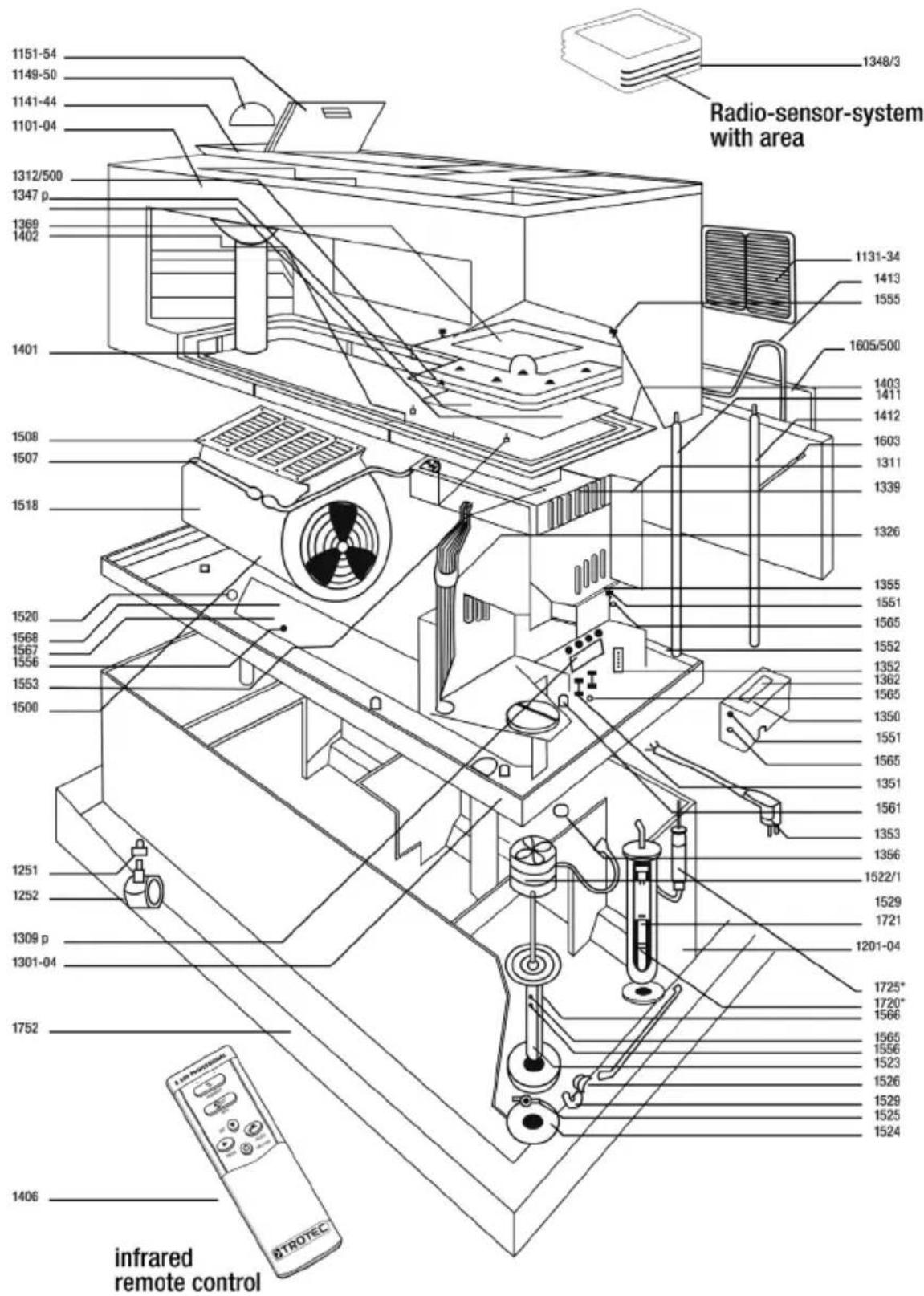
23. Maintenance check lists
⚠️ Only authorised and qualified staff are permitted to carry out the following work!
| Time interval* | Cleaning and operating instructions(Always disconnect mains supply plug before performing any work on the device!) |
| Every day | Visual check of water level via LED display (10-50) litres. Device switches off automatically at residual water level of approx. 15 litres.Does not apply in case of automatic water supply.Visual check of indicated humidity value via digital display. |
| 3-5 weeks | Lift upper part of device upwards.Visual check of filter. In case of strong pollution replace filter. (Use original filters only, otherwise operation of the device may be impaired). When inserting the new filter, always take care that it will be inserted flush with water distribution system (see operation manual „Replacing filters“).The two lateral snap bows of the filter must be inserted properly, since otherwise the filter can come into contact with the upper part of the casing, which may cause water escapes.Please check at the same time whether the outlet holes in the water distribution system are free from residues. Remove any residues such as lime or dust for instance, by means of a needle, a screwdriver or even use a vacuum cleaner for this.Lift middle part of device off in upward direction.Remove remaining water from the water container and clean the tub (bottom part).This is necessary in particular when using fresh water in order to avoid higher concentrations of residues.Visual check of the copper electrode bars (see operation manual). Remove lime and other residues by means of a household sponge, or if necessary use a rag for this. |
| 12-16 weeks | As described in the above section the filter must be replaced after 12 to 16 weeks in any case, since otherwise the operation of the device may be impaired. When replacing the filter check the water distribution for passage.After this time has elapsed and in case of heavy calcification and dirt deposits the water tub (bottom part) should be cleaned by means of an anti-lime agent from an anti-lime agent that is customary in the trade. After cleaning with such an agentalways rinse the water tube well in order to avoid residues remaining in the device. |
| 12 months | General cleaning of the device by means of anti-lime agent - clean pump tubes using a bottle brush or replace them - clean the body of the fan by using the extension nozzle of the vacuum cleaner - clean the body of the pump - clean the copper electrodes |
| Time interval* | Cleaning and operating instructions(Always disconnect mains supply plug before performing any work on the device!!!) |
| 12 months | With the type of equipment using UV degermination and lime conversion: Check and clea the UV-lamp and the lime conversion cartridge (see sheet on UV degermination and lime conversion cleaning) After cleaning, always rinse with clear water to avoid residues of the anti-lime agent remaining in the device:Do not use agents that contain benzene or other agent types likely to affect plastic when cleaning.Visual check of UV-lamp operation. Operation of the UV-lamp is indicated while the device is working.If the UV-lamp has to be replaced (Operating life 5,000-8,000 hours), proceed as described in the operating instructions under „Replacing the UV-tube“.Lift the upper part of the device upwards for cleaning the lime conversion cartridge.Lift the centre plate upwards out of the water tank (lower part).The UV-degermination arrangement is located below the centre plate next to the pump.Inspect stainless steel tube visually and remove fouling.Withdraw pump hoses from the stainless steel tube and check the passage of the stainless steel tube hoses. Remove fouling.Take care that the quartz glass body is not damaged.The lime conversion cartridge (blue) is located on the right side between the water feed and the centre plate of the device.The pump hoses can be removed by pulling them off.Visually check the passage. Carefully remove lime deposits with a drill (max. diameter 7 mm) or screwdriver.Take care when fitting that the hoses are securely seated on the plug connector. |
* The time intervals indicated apply in case of normal water and normal production of dust in the air and may thus vary either in length or even require shorter cleaning intervals.
The batteries must be removed before the appliance is scrapped.
They must not be thrown in the dustbin but handed in for proper disposal.
24. Correcting faults
If your device is not working properly, please check the following points:
| Problem Cause What to do? | ||
| No functionality Device not connected Check mains connector | ||
| Water tank symbol lights red No water Fill with water | ||
| Device does not start up Humidity is higher than the desired humidity set „Enter“ was not pressed when altering the humidity value or blower stageWater indicator copper electrodes fouled | If appropriate change the set value After changing the value always press „Enter“ on the remote controlClean copper electrodes | |
| Device runs but does not take in any water | Pump hoses not correctly fitted or fouledLime conversion cartridge clogged 1)Pump defect | Clean pump hoses or fit correctlyClean or bore out cartridgeReplace pump |
| Water channel overflows Outflow holes are clogged Clean water distribution and outflow holes | ||
| Water is escaping from the device | Filter is usedFilter is not correctly installed | Renew filterCheck the filter seating |
| Water degermination monitor lamp does not light 1) | UV-source defect Replace UV-source | |
| Device does not respond to the remote control | Battery discharged or incorrectly installedDistance between remote control and device too great | Check battery and replace ; note +/-Reduce distance |
| Automatic water feed no longer replenishes water 2) | Safety pressure hose defect – Water feed is automatically stopped | Replace hose |
| Water feed runs continuously 3) | Water feed floater stuck Remove fouling in the feed, replace float | |
| Water monitor outputs acoustic signal 3) | Water has escaped Check cause. Separate the feeding line to the water monitor from the mains for a few seconds | |
| Radio transmitter outputs acoustic signal | Batteries in transmitter are discharged Replace batteries | |
| Newly fitted batteries are not working | Battery were incorrectly fitted (polarity not observed) | Fit new batteries |
1) Only for special UV-technology version with lime conversion cartridge
2) Only for special automatic water feed version with safety pressure hose
3) Only for special electronic water monitor version
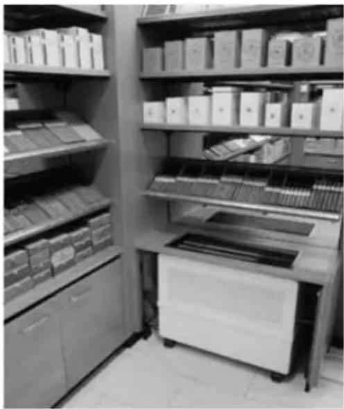
25. Installation suggestions
During installation care must be taken to ensure that adequately large openings are available for air intakes and outlets to ventilate the appliance.
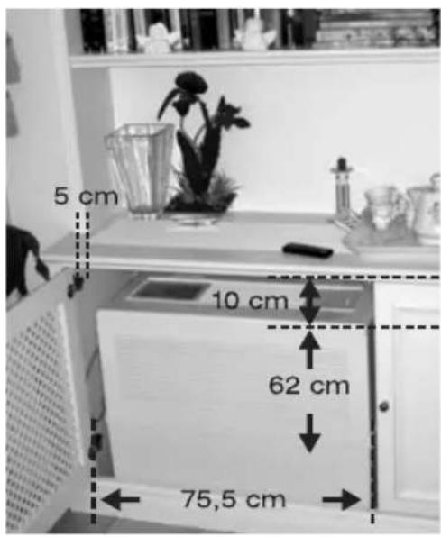
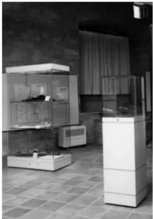
Living-room area Equipment in a specialist shop / walk-in humidor

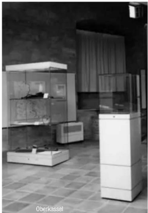
Possible uses in the museum area... ...or in churches to protect valuable organs.
26. Technical data
Power supply 230 V/50 HZ
Power consumption max. 95 VA (without additional equipment)
Air flow capacity 900 m³/h
Evaporation capacity 2,6 ltr./h on 250 C and 20% r.H.
Evaporation filter area 3,5 m²
Weight (empty) approx. 24 kg
Water reservoir approx. 50 ltr
Dimensions L: 75.5 x H: 62.0 x W: 36.5 cm
⚠️ Disconnect the mains plug before opening the equipment!
RéSUMÉE
19. Nettoyage

- INHALT
- REINIGUNG
- COMMISSIONING
- COMMISSIONING CHECK LIST
- LOCATION
- POWER CONSUMPTION
- HUMIDITY
- CONTROL PANEL AT A GLANCE
- 1 HUMIDITY BUTTON
- 2 FAN TASTE
- 3 SET BUTTON
- 4 PROG BUTTON
- 5 FLUSH BUTTON
- 6 ON/OFF-TASTE
- FILLING
- (NOT APPLICABLE FOR HUMIDIFIERS WITH AUTOMATIC WATER SUPPLY)
- WATER LEVEL INDICATOR
- FILTER CHANGE INDICATOR
- FILTER CHANGE
- CHANGING THE CONTROL PANEL
- PLEASE PROCEED AS FOLLOWS
- CONNECTIONS ON THE CIRCUIT BOARD
- CONNECTION DESCRIPTION POWER SUPPLY POWER
- FAN SETTINGS
- CHANGING THE FAN
- RADIO-SENSOR-SYSTEM (RADIO FREQUENCY 435 MHZ)
- STARTING UP
- ⚠ MAKE SURE THE POLES (+/-) ARE INSERTED CORRECTLY
- CODING THE RADIO SENSOR SYSTEM
- CODING THE SENSOR
- PROCEDURE
- FAULT CODE DISPLAY
- MENU PROGRAMMING
- WATER PUMP
- HYGIENE PRODUCTS
- CLEANING
- ⚠ DO NOT USE BENZENE OR OTHER SOLVENTS THAT ATTACK PLASTIC
- AUTOMATIC WATER SUPPLY
- ⚠ THE MAXIMUM WATER PRESSURE MUST NOT EXCEED 10 BAR
- AUTOMATIC RINSING SYSTEM
- ACTIVATED CHARCOAL CLEANING FILTERS
- AIR SCOOP WITH FLEXIBLE HOSE
- UV-TECHNOLOGY WITH CALCIUM CONVERSION CARTRIDGE
- CHANGING UV-TUBES
- PARTS LIST
- OPTIONAL EXTRAS AND ACCESSORIES
- MAINTENANCE CHECK LISTS
- CORRECTING FAULTS
- INSTALLATION SUGGESTIONS
- TECHNICAL DATA
- RÉSUMÉE
- NETTOYAGE
Brand : TROTEC
Model : B 500
Category : Humidifier