
TempTrend 7004001 - Weather Station BRESSER - Free user manual and instructions
Find the device manual for free TempTrend 7004001 BRESSER in PDF.
| Product Type | Radio-controlled weather station with wireless outdoor sensor |
| Brand | Bresser |
| Model | TempTrend 7004001 |
| Base station dimensions | 100 x 180 x 29 mm |
| Base station weight | 225 g (without batteries) |
| Remote sensor dimensions | 56 x 105 x 30 mm |
| Remote sensor weight | 69 g (without batteries) |
| Base station power supply | 2 x 1.5 V UM-3 / AA batteries |
| Remote sensor power supply | 2 x 1.5 V UM-3 / AA batteries |
| Indoor temperature range | -5.0 °C to +50.0 °C |
| Outdoor temperature range | -10 °C to +50 °C |
| Humidity range | 25% to 95% RH |
| Radio transmission frequency | 433 MHz |
| Maximum radio range | 30 meters in open field |
| Number of sensor channels | 3 |
| Radio-controlled clock | Yes, DCF77 reception |
| Weather forecast display | Based on air pressure, icons (sunny, cloudy, rainy, snowy) |
| Frost alert function | Yes, icon displayed if outdoor temperature < 3 °C |
| Air pressure display | With trend (rising, steady, falling) |
| Maintenance and cleaning | Clean the exterior with a clean, dry cloth. Do not use cleaning liquids. |
| Safety | Do not expose to heat, do not disassemble, use only recommended batteries/power adapter, keep out of reach of children. |
| Spare parts and repairability | No user-serviceable parts. Contact the dealer if damaged. |
| Warranty | 2 years from purchase, extension possible upon registration at www.bresser.de/warranty_terms |
Frequently Asked Questions - TempTrend 7004001 BRESSER
User questions about TempTrend 7004001 BRESSER
0 question about this device. Answer the ones you know or ask your own.
Ask a new question about this device
Download the instructions for your Weather Station in PDF format for free! Find your manual TempTrend 7004001 - BRESSER and take your electronic device back in hand. On this page are published all the documents necessary for the use of your device. TempTrend 7004001 by BRESSER.
USER MANUAL TempTrend 7004001 BRESSER
Weather Station with Wireless Outdoor Sensor
C RÜCKSETZ-TASTE [RESET]
D KANAL-SCHALTER
ABLESEN DES "WELLEN"-INDIKATORS
DANGER to your child! RISK of physical injury!
This device contains electronic components that are powered by either a mains connection or batteries. Never leave a child unsupervised with this device. The device should only be used as per these instructions otherwise there is a serious RISK of ELECTRICAL SHOCK.
Children should only use this device under supervision. Keep packaging materials (plastic bags, rubber bands, etc.) away from children. There is a risk of SUFFOCATION.
Batteries should be kept out of children's reach. When inserting batteries please ensure the polarity is correct. Leaking or damaged batteries can cause injury if they come into contact with the skin. If you need to handle such batteries please wear suitable safety gloves.
DANGER of fire and explosion!
Do not expose the device to high temperatures. Use only the mains adapter supplied or those battery types recommended. Never short circuit the device or batteries or throw into a fire. Exposure to high temperatures or misuse of the device can lead to short circuits, fire or even explosion!
RISK of material damage!
Never take the device apart. Please consult your dealer if there are any defects. The dealer will contact our service centre and send the device in for repair if needed.
Only use the batteries that have been recommended. Always replace low or used batteries with a completely new set of full capacity batteries. Do not combine batteries of different brand, type or capacity. Batteries should be removed from the device after long periods of disuse.
TIPS on cleaning

Remove the device from it's energy source before cleaning (remove plug from socket / remove batteries).
Clean the exterior of device with a dry cloth. Do not use cleaning fluids so as to avoid causing damage to electronic components.
DISPOSAL

Dispose of the packaging material/s as legally required. Consult the local authority on the matter if necessary.
Do not dispose of electrical equipment in your ordinary refuse. The European guideline 2002/96/EU on Electronic and Electrical Equipment Waste and relevant laws applying to it require such used equipment to be separately collected and recycled in an environment-friendly manner.
In accordance with the regulations concerning batteries and rechargeable batteries, disposing of them in the normal household waste is explicitly forbidden. Please pay attention to dispose of your used batteries as required by law - at a local collection point or in the retail market (a disposal in domestic waste violates the Battery Directive).
Batteries that contain toxins are marked with a sign and a chemical symbol. „Cd“ = cadmium, „Hg“ = mercury, „Pb“ = lead.
Cd1
Hg2
Pb3
1 battery contains cadmium
2 battery contains mercury
3 battery contains lead
Remote Sensor
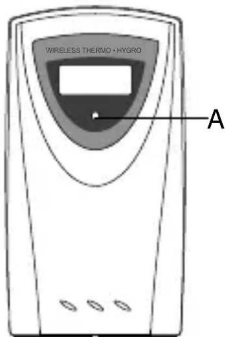
A Outdoor Temperature and Humidity as well as LED Control Light
Flashes once when remote unit transmits a reading and twice when the batteries are low.
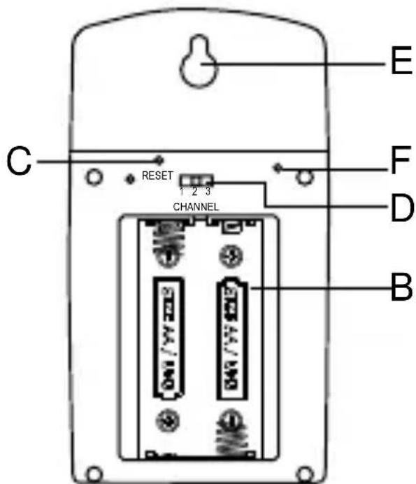
B Battery Compartment
Accommodates 2 Mignon batteries (1.5V, Type AA).
C Reset Button
Resetting of all functions after changing the channels.
D Channel Selector
Channel is to be selected at channel 1.
E Wall Mount Hole
For mounting the sensor on the wall.
F ^ / ^ Switch
Selects between Centigrade (^) and Fahrenheit (^) .
BEFORE YOU BEGIN
For best operation,
- Insert batteries for the main unit before doing so for the remote unit.
- Place the main unit as close as possible next to the remote unit.
- Position the remote unit and main unit within effective transmission range.
Note that the effective range is vastly affected by the building materials and where the main and remote units are positioned. Try various set-ups for best result.
Though the remote units are weather proof, they should be placed away from direct sunlight, rain or snow.
BATTERY INSTALLATION: MAIN UNIT
- Open the battery compartment door.
- Install 2 batteries (UM-3 or "AA" size 1.5V) strictly according to the polarities shown.
- Replace the battery compartment door.
BATTERY INSTALLATION: REMOTE UNIT
- Remove the screws on the battery compartment.
- Select the channel
- Install 2 batteries (UM-3 or "AA" size 1.5V) strictly according to the polarities shown.
- Replace the battery compartment door and secure its screws.
LOW BATTERY WARNING
When it is time to replace batteries, the respective low-battery indicator will show up on the indoor or outdoor temperature.
INTRODUCTION:
Congratulations with the purchase if the In/Out Therm odometer with wireless sensor and radio controlled clock.
The basic package comes with a main unit (the temperature/clock station) and a remote unit (the thermo sensor).
The main unit has large displays for time/date, indoors temperature and humidity, outdoors temperature and humidity as received from the remote unit. The main unit can receive data from remote units.
The remote units have a range up to 30 meters, this range can be influenced by several factors (concrete walls, electric wires, other sending devices, etc.)
The sensors are weatherproof and can be used outdoors, but should not be submerged into water or hung in a place where rain can reach the unit.
The clock/calendar function is radio controlled.
Attention! For first time operation and battery replacement: First insert batteries for main unit and then insert batteries for remote sensor.
The clock is synchronised with the atom clock in Frankfurt Germany, this clock has a range of 1.500 km and your clock will receive the time signal 12 to 24 times a day and will correct, if necessary. When you first operate your clock, it can take up to 60 minutes before the radio signal is received and the correct time is set.
When you put the main unit and the remote unit next to each other, you will notice a minimal difference in temperature. This is caused by the software used and the insulation of the outdoors sensor, this sensor is calibrated on the average outdoors temperature, whereas the main unit is calibrated on the average indoors temperature. This is no defect in the units
At temperatures below freezing point the operation can be distorted, this is caused because the batteries cannot deliver the power needed to operate the unit correctly. You can avoid this by using branded batteries and change them just before the winter starts.
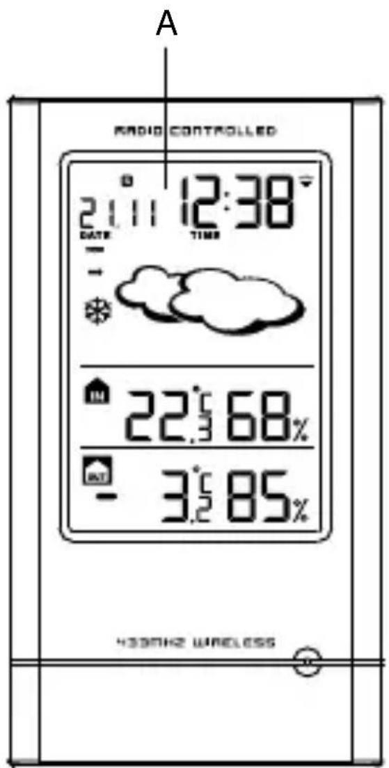
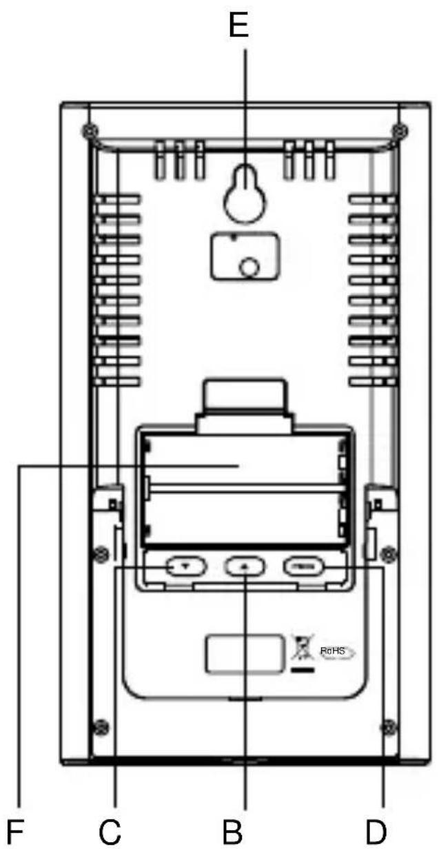
A DISPLAY
Facilitates easy reading of weather forecast, indoor and outdoor humidity remote and indoors temperature and calendar clock.
BUP (▲) BUTTON
Increases the value of a setting.
Selects the pressure or calendar reading and toggle between ^ C and ^ F .
C DOWN (▼) BUTTON
Decreases the value of a setting.
Activates the radio signal reception and enforce the remote channel search function.
D MODE toets
Enters the setting mode for time and date.
E WALL-MOUNT RECESSED HOLE
For mounting the main unit on a wall.
F BATTERY COMPARTMENTS
Accommodates two UM-3 or LR6 (AA) 1.5V batteries.
HOW TO USE THE TABLE STAND OR WALL MOUNTING
The main unit has a removable table stand, which when connected, can support the unit on a flat surface. Or you can remove the stand and mount the unit on a wall using the recessed screw hole. As for the remote unit, you can place it on a flat surface or mount the unit on a wall using the recessed screw hole.
GETTING STARTED
Once batteries are in place for the remote unit, they will start transmitting temperature readings at around 45 seconds intervals. The main unit will also start searching for signals for about two minutes once batteries are installed. Upon successful reception, the outdoors temperatures will be displayed on the top line and the indoors temperature on the bottom line. The main unit will automatically update its readings at about 45-second intervals.
If no signals are received, blanks “…” will be displayed. Hold [▼] for 2 seconds to enforce another search for about 2 minutes. This is useful in synchronizing the transmission and reception of the remote and main units.
Repeat this step whenever you find discrepancies between the reading shown on the main unit and that on the remote unit.
HOW TO CHECK REMOTE AND INDOOR TEMPERATURES
The indoors temperature is shown on the second line of the display. The outdoors temperature is shown on the top line of the display.
The wave display on the outdoors temperature indicates the reception of the remote unit is in good order.
If no readings are received from the remote unit for more than two minutes, blanks “…” will be displayed until further readings are successfully searched.
Check the remote unit is sound and secure. You can wait for a little while or Hold [] for 2 seconds to enforce an immediate search. If the temperature goes above or below than the temperature measuring range of the main unit or the remote unit (stated in specification), the display will show “...”
HOW TO READ THE KINETIC WAVE DISPLAY
The kinetic wave display shows the signal receiving status of the main unit. There are three possible forms:
| The unit is in searching mode. | |
| Temperature readings are securely registered. | |
| No signals. |
Weather Forecast
This unit is capable of detecting atmospheric pressure changes. Based on collected date it can predict the weather for the forthcoming 12 to 24 hours.
| Display | |||
| Forecast | CloudySlightly cloudy | ||
| Display | |||
| Forecast | SnowyHeavy RainRain |
Note:
- The accuracy of a general pressure-based weather forecast is 70% .
- The weather forecast indicates the forthcoming change and not necessarily the current situation.
- The symbol “Sunny” applies also to night time.
It indicates clear skies/without clouds.
ATMOSPHERIC PRESSURE
The atmospheric pressure indicator, in the weather forecast window, uses arrows to indicate if the atmospheric pressure is increasing, remaining stable, or decreasing.
| Arrow indicator | TREND | TREND | TREND |
| ↑ | → | ↓ | |
| Pressure Trend | Steady Falling | Rising |
FREEZING ALERT
The freeze alert symbol lights up in the display when outside temperature falls below 3^ (as transmitted by remote sensor channel 1).
As soon as the temperature rises above 6^ the symbol will disappear from the display.

DISCONNECTED SIGNALS
If without obvious reasons the display of the outdoor temperature goes blank, Check:
- The remote unit is still in place.
- The batteries of both the remote unit and main unit. Replace as necessary.
Note: When the temperature falls below freezing point, the batteries of outdoor units will freeze, lowering their voltage supply and the effective range.
- The transmission is within range and path is clear of obstacles and interference. Shorten the distance when necessary.
Signals from other household devices, such as door bells, home security systems and entry controls, may interfere with those of this product and cause temporarily reception failure. This is normal and does not affect the general performance of the product. The transmission and reception of temperature readings will resume once the interference recedes.
HOW TO SET THE RADIO CONTROLLED CLOCK
- After the batteries are installed. The clock will automatically search the radio signal. It takes about
3-5 minutes to finish this process. - If the radio signal is received, the date & time will be set automatically with radio control signal icon [ turns on.
- If the clock fails to receive the time signal, it will be show as [ ] icon. Then user can set the time manually.
CALENDAR / BAROMETER DISPLAY
The calendar date will be displayed in day-month format. Press and hold the [▲] button for 2 seconds to change from date to barometer display.
RADIO CONTROLLED CLOCK
The radio controlled signal for time (DCF 77) is transmitted from the central atomic clock in Frankfurt/ Main in short intervals. It has a reception range of approx. 1500km . Obstructions such as concrete walls can reduce the signal range.
If the search for the radio signal is not successful the aforementioned symbol will not appear. Instead the symbol for signal search will be displayed. In this case the time is to be set manually.
Press [▼] button for 2 seconds, in order to switch off the radio controlled quartz function. The symbol for radio signal transmission will be deleted. By again pressing the [▼] button for 2 seconds the radio controlled reception will be again be turned on. The time change from standard to daylight saving time and back is done automatically. Visible through the icon on the display.
HOW TO SET THE CLOCK MANUALLY
To set the clock manually, hold MODE for two seconds it will show the year. Use [▲] or [▼] to change it. Press MODE to confirm. Repeat the same procedure to set month, date, date-month format, 12/24, hours, minutes. During the setting, press and hold [▲] or [▼] will increase or decrease the value rapidly. If there is an item you do not wish to change, simply press [MODE] to bypass the item. When you finished the change, press [MODE] to exit. The display will return to the clock mode.
PRECAUTIONS
This product is engineered to give you years of satisfactory service if you handle it carefully. Here are a few precautions:
- Do not immerse the unit in water.
- Do not clean the unit with abrasive or corrosive materials. They may scratch the plastic parts and corrode the electronic circuit.
- Do not subject the unit to excessive force, shock, dust, temperature or humidity, which may result in malfunction, shorter electronic life span, damaged battery and distorted parts.
- Do not tamper with the unit's internal components. Doing so will invalidate the warranty on the unit and may cause unnecessary damage. The unit contains no user-serviceable parts.
- Only use fresh batteries as specified in the user's manual. Do not mix new and old batteries as the old ones may leak.
- Always read the user's manual thoroughly before operating the unit.
CAUTION
- The content of this manual is subject to change without further notice.
- Due to printing limitation, the displays shown in this manual may differ from the actual display.
- The contents of this manual may not be reproduced without the permission of the manufacturer.
SPECIFICATIONS
Temperature Measurement
Main unit
Indoor Temperature measurement
Proposed operating range : -5.0°C to +50.0°C 23.0°F to 122.0°F
Humidity Measuring range : R.H. 25% to 95% at 25^ C( 77^ F)
Temperature resolution : 0.1^
Humidity resolution : 1% R.H.
Remote unit
Proposed operating range : -10°C to + 50°C 23°F to 122°F
Temperature resolution : 0.1^
RF Transmission Frequency : 433 MHz
RF Transmission Range : Maximum 30
Temperature sensing cycle : around 43~47
Remote relative humidity : 25% RH to 95% RH measurement range
Resolution
: 1%RH
Calendar Clock
24 h display with hh : mm
Date Format : Day - Month or Month-Day.
Power
Main unit : use 2 pcs UM-3 or "AA"
Remote sensing unit : use 2 pcs UM-3 or "AA"
1.5V
1.5V
Weight
Main unit : 225g (without battery) Remote sensing unit : 69g (without battery)
Dimension
Main unit : 100(L) x 180(H) x 29(D) mm Remote sensing unit : 56(L) x 105(H) x 30(D) mm
EC-DECLARATION OF CONFORMITY
CE
Product: TempTrend
Bresser GmbH declares that the device (Weather station/Art.No.: 70-04000) is in accordance with applicable guidelines and corresponding standards of the 1999/5/EG directive.
Bresser GmbH has issued a Declaration of Conformity in accordance with applicable guidelines and corresponding standards. This can be viewed any time upon request.
WARRANTY & SERVICE
The regular guarantee period is 2 years and begins on the day of purchase. To benefit from an extended voluntary guarantee period as stated on the gift box, registration on our website is required.
You can consult the full guarantee terms as well as information on extending the guarantee period and details of our services at www.bresser.de/warranty_terms.
Would you like detailed instructions for this product in a particular language? Then visit our website via the link below (QR code) for available versions. Alternatively you can also send an email to manuals@bresser.de or leave a message on +49 (0) 28 72 - 80 74-220*. Please always state your name, precise address, a valid phone number and email address, as well as the article number and name.
*Number charged at local rates in Germany (the amount you will be charged per phone call will depend on the tariff of your phone provider); calls from abroad will involve higher costs.

B Compartment des Piles
Reçoit 2 piles R6 (1.5V, Type AA).
2d) INDICADOR DE PILA “VACÍA”

- C RÜCKSETZ-TASTE [RESET]
- D KANAL-SCHALTER
- ABLESEN DES "WELLEN"-INDIKATORS
- DANGER to your child! RISK of physical injury!
- DANGER of fire and explosion!
- RISK of material damage!
- TIPS on cleaning
- DISPOSAL
- Remote Sensor
- A Outdoor Temperature and Humidity as well as LED Control Light
- B Battery Compartment
- C Reset Button
- D Channel Selector
- E Wall Mount Hole
- F °C / °F Switch
- BEFORE YOU BEGIN
- BATTERY INSTALLATION: MAIN UNIT
- BATTERY INSTALLATION: REMOTE UNIT
- LOW BATTERY WARNING
- INTRODUCTION:
- A DISPLAY
- BUP (▲) BUTTON
- C DOWN (▼) BUTTON
- D MODE toets
- E WALL-MOUNT RECESSED HOLE
- F BATTERY COMPARTMENTS
- HOW TO USE THE TABLE STAND OR WALL MOUNTING
- GETTING STARTED
- HOW TO CHECK REMOTE AND INDOOR TEMPERATURES
- HOW TO READ THE KINETIC WAVE DISPLAY
- Weather Forecast
- Note:
- ATMOSPHERIC PRESSURE
- FREEZING ALERT
- DISCONNECTED SIGNALS
- HOW TO SET THE RADIO CONTROLLED CLOCK
- CALENDAR / BAROMETER DISPLAY
- RADIO CONTROLLED CLOCK
- HOW TO SET THE CLOCK MANUALLY
- PRECAUTIONS
- CAUTION
- SPECIFICATIONS
- Power
- Weight
- Dimension
- EC-DECLARATION OF CONFORMITY
- CE
- WARRANTY & SERVICE
- 2d) INDICADOR DE PILA “VACÍA”
Brand : BRESSER
Model : TempTrend 7004001
Category : Weather Station