CNS 125 U - Pan STIEBEL ELTRON - Free user manual and instructions
Find the device manual for free CNS 125 U STIEBEL ELTRON in PDF.
| Product type | Wall-mounted electric convector |
| Brand | Stiebel Eltron |
| Model | CNS 125 U |
| Heating power | 1.25 kW |
| Electrical supply | 230 V ~ 50 Hz, single-phase |
| Height | 450 mm |
| Width | 445 mm |
| Depth (with wall bracket) | 78 mm |
| Weight | 5.6 kg |
| Temperature setting range | Approximately 6 to 30 °C |
| Frost protection | Approximately 6 °C |
| Protection class | II |
| Protection rating | IP24 (protection against water splashes) |
| Operating type | Natural convection |
| Safety device | Protection temperature controller (STR) against overheating |
| Minimum safety distances | Air outlet: 500 mm; sides: 100 mm; top: 150 mm; bottom: 100 mm; rear: 26 mm |
| Electrical connection | Power outlet with protective contact or fixed connection box |
| Maintenance | Clean with a damp cloth and clear water, appliance cold. Do not use abrasive or corrosive products. |
| Spare parts | Power cable replaceable only with Stiebel Eltron original parts |
| Warranty | According to conditions of the country of purchase, 10 years for safety components? (verification by installer at the latest 10 years after commissioning) |
| Recommended use | Main heating in bathroom or supplementary heating in small rooms |
| Instructions included | Yes, instructions for use and installation |
Frequently Asked Questions - CNS 125 U STIEBEL ELTRON
User questions about CNS 125 U STIEBEL ELTRON
0 question about this device. Answer the ones you know or ask your own.
Ask a new question about this device
Download the instructions for your Pan in PDF format for free! Find your manual CNS 125 U - STIEBEL ELTRON and take your electronic device back in hand. On this page are published all the documents necessary for the use of your device. CNS 125 U by STIEBEL ELTRON.
USER MANUAL CNS 125 U STIEBEL ELTRON
CNS 50 S, CNS 75 S, CNS 100 S, CNS 125 S, CNS 150 S, CNS 175 S, CNS 200 S, CNS 250 S, CNS 300 S
CNS 50 U, CNS 75 U, CNS 100 U, CNS 125 U, CNS 150 U, CNS 175 U, CNS 200 U, CNS 250 U, CNS 300 U
Deutsch
Wand-Konvektor
Wall mounted convector heater
Operation and installation instructions
Français
Convecteur mural
- Operating instructions 8
1.1 Description
1.2 Operation
1.3 Safety notes
1.4 Care and maintenance
What to do if . . .? 9
- Installation instructions 9
2.1 Structure of unit
2.2 Provisions and specifications
2.3 Installation
2.4 Electrical connection
2.5 Handover
Technical data 10
3.Environment and recycling 10
4.Guarantee 10
Table des matieres
Français
page 11 - 13
Wate doen als...? 15
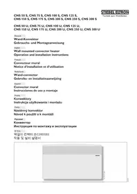
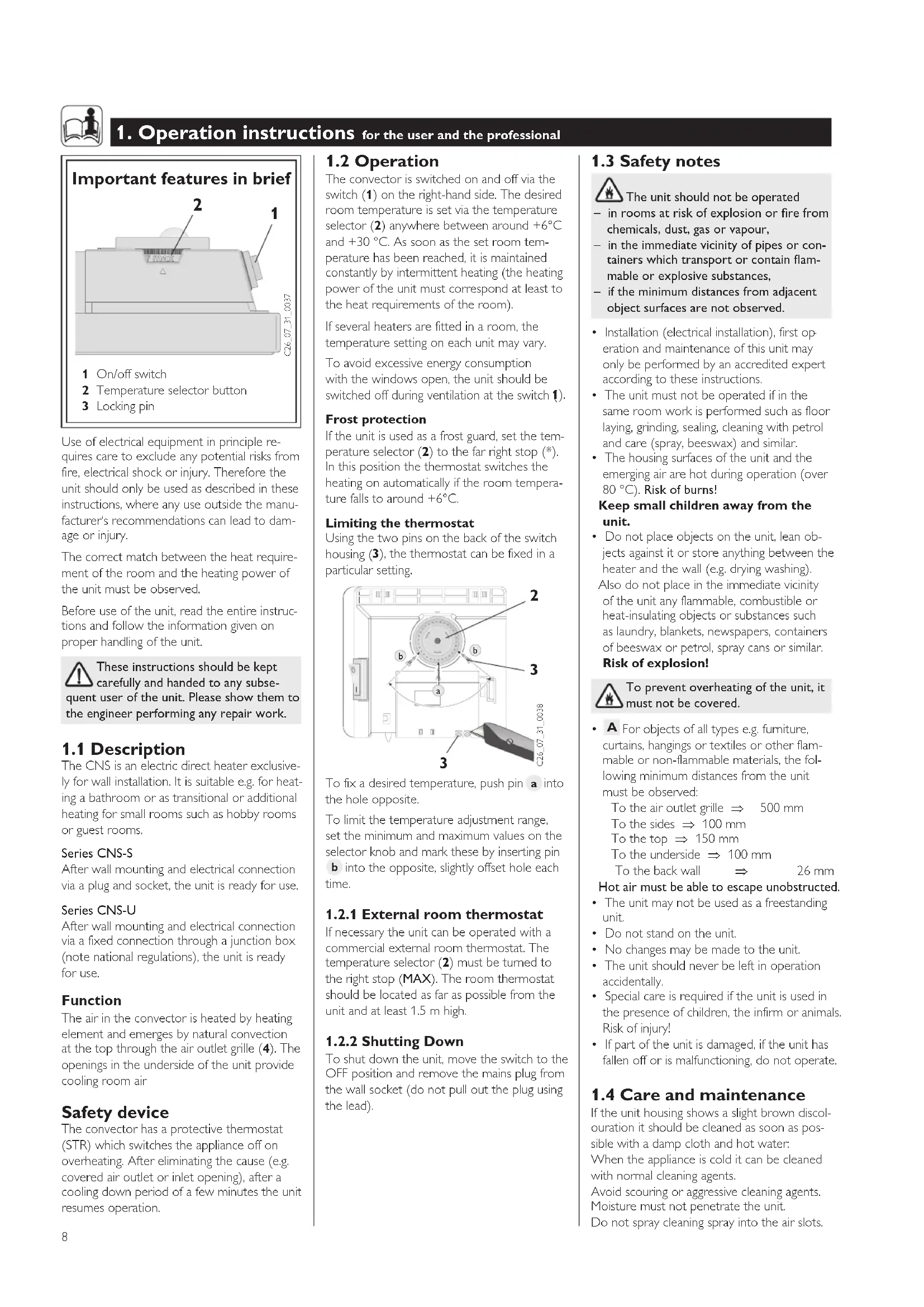
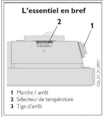
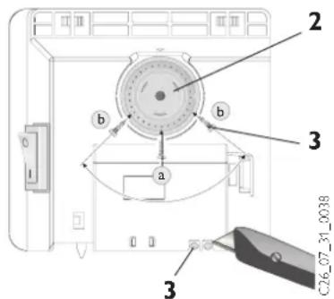
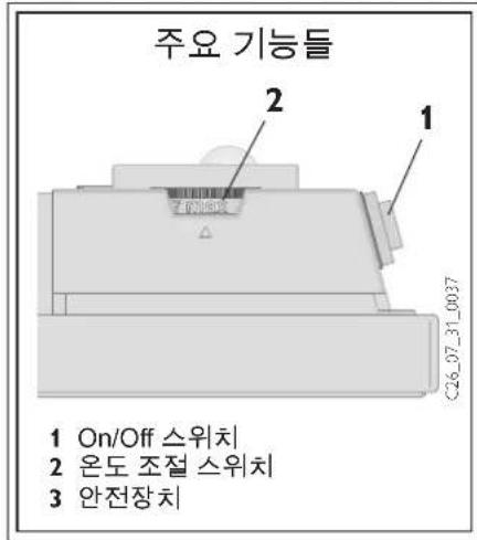
Important features in brief
1 On/off switch
2 Temperature selector button
3 Locking pin
Use of electrical equipment in principle requires care to exclude any potential risks from fire, electrical shock or injury. Therefore the unit should only be used as described in these instructions, where any use outside the manufacturer's recommendations can lead to damage or injury.
The correct match between the heat requirement of the room and the heating power of the unit must be observed.
Before use of the unit, read the entire instructions and follow the information given on proper handling of the unit.
These instructions should be kept carefully and handed to any subsequent user of the unit. Please show them to the engineer performing any repair work.
1.1 Description
The CNS is an electric direct heater exclusively for wall installation. It is suitable e.g. for heating a bathroom or as transitional or additional heating for small rooms such as hobby rooms or guest rooms.
Series CNS-S
After wall mounting and electrical connection via a plug and socket, the unit is ready for use.
Series CNS-U
After wall mounting and electrical connection via a fixed connection through a junction box (note national regulations), the unit is ready for use.
Function
The air in the convector is heated by heating element and emerges by natural convection at the top through the air outlet grille (4). The openings in the underside of the unit provide cooling room air
Safety device
The convector has a protective thermostat (STR) which switches the appliance off on overheating. After eliminating the cause (e.g. covered air outlet or inlet opening), after a cooling down period of a few minutes the unit resumes operation.
1.2 Operation
The convector is switched on and off via the switch (1) on the right-hand side. The desired room temperature is set via the temperature selector (2) anywhere between around +6^ and +30^ . As soon as the set room temperature has been reached, it is maintained constantly by intermittent heating (the heating power of the unit must correspond at least to the heat requirements of the room).
If several heaters are fitted in a room, the temperature setting on each unit may vary.
To avoid excessive energy consumption with the windows open, the unit should be switched off during ventilation at the switch 1).
Frost protection
If the unit is used as a frost guard, set the temperature selector (2) to the far right stop (^*) . In this position the thermostat switches the heating on automatically if the room temperature falls to around +6^ .
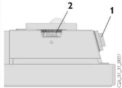
Limiting the thermostat
Using the two pins on the back of the switch housing (3), the thermostat can be fixed in a particular setting.
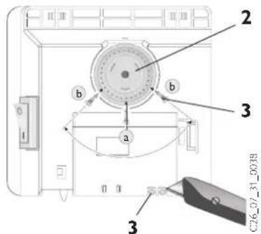
To fix a desired temperature, push pin a into the hole opposite.
To limit the temperature adjustment range, set the minimum and maximum values on the selector knob and mark these by inserting pin b into the opposite, slightly offset hole each time.
1.2.1 External room thermostat
If necessary the unit can be operated with a commercial external room thermostat. The temperature selector (2) must be turned to the right stop (MAX). The room thermostat should be located as far as possible from the unit and at least 1.5 m high.
1.2.2 Shutting Down
To shut down the unit, move the switch to the OFF position and remove the mains plug from the wall socket (do not pull out the plug using the lead).
1.3 Safety notes
The unit should not be operated
- in rooms at risk of explosion or fire from chemicals, dust, gas or vapour,
- in the immediate vicinity of pipes or containers which transport or contain flammable or explosive substances,
-
if the minimum distances from adjacent object surfaces are not observed.
-
Installation (electrical installation), first operation and maintenance of this unit may only be performed by an accredited expert according to these instructions.
The unit must not be operated if in the same room work is performed such as floor laying, grinding, sealing, cleaning with petrol and care (spray, beeswax) and similar. - The housing surfaces of the unit and the emerging air are hot during operation (over 80^ ). Risk of burns!
Keep small children away from the unit.
- Do not place objects on the unit, lean objects against it or store anything between the heater and the wall (e.g. drying washing). Also do not place in the immediate vicinity of the unit any flammable, combustible or heat-insulating objects or substances such as laundry, blankets, newspapers, containers of beeswax or petrol, spray cans or similar.
Risk of explosion!
To prevent overheating of the unit, it must not be covered.
- A For objects of all types e.g. furniture, curtains, hangings or textiles or other flammable or non-flammable materials, the following minimum distances from the unit must be observed:
To the air outlet grille 500 mm
To the sides 100mm
To the top 150mm
To the underside 100mm
To the back wall 26 mm
Hot air must be able to escape unobstructed.
The unit may not be used as a freestanding unit.
- Do not stand on the unit.
No changes may be made to the unit.
The unit should never be left in operation accidentally.
Special care is required if the unit is used in the presence of children, the infirm or animals. Risk of injury!
If part of the unit is damaged, if the unit has fallen off or is malfunctioning, do not operate.
1.4 Care and maintenance
If the unit housing shows a slight brown discolouration it should be cleaned as soon as possible with a damp cloth and hot water.
When the appliance is cold it can be cleaned with normal cleaning agents.
Avoid scouring or aggressive cleaning agents. Moisture must not penetrate the unit.
Do not spray cleaning spray into the air slots.
For regular maintenance we recommend checking the control and adjustment elements.
At the latest 10 years after first use, the safety, control and adjustment elements should be checked by an expert.
What to do if . . .?
the unit does not get hot?
Chechk that ...
... the ON/OFF switch is turned on.
... in your fuse box, the corresponding fuse is intact or whether the breaker has tripped.
Eliminate cause!
If the heater still does not warm up, call an engineer!
the unit switches itself off?
Check whether it is covered, so it could have overheated (e.g. covered air outlet or inlet opening).
- customer service is called?
Eliminate cause!
If it does not warm up again after a few minutes' cooling down period, call an engineer!
Read the type (Typ) and number (Nr.) from the rating plate (8) on the unit and tell customer service!
STIEETRON Typ:CNS.

2. Installation instructions for the professional
This unit may only be erected and electrically connected by a specialist following the installation instructions.
First remove the packaging and check accessories and any enclosures, ensure that no accessories remain in the packaging material.
2.1 Structure of unit
4 Air outlet grid
5 Wall bracket
6 Closing bolt
7 Mains connection cable
8 Rating plate
2.2 Provisions and specification

The unit should not be operated
- in rooms at risk of explosion or fire from chemicals, dust, gas or vapour,
- in the immediate vicinity of pipes or containers which transport or contain flammable or explosive substances,
- if the minimum distances from adjacent object surfaces are not observed.
In workshops or other rooms in which exhaust gases, oil or petrol vapours etc. occur or where solvents and chemicals are used, persistent odour problems and where applicable contamination can occur.
The unit may only be fitted to a vertical wall, temperature-resistant up to at least 80^
- Minimum distances from adjacent object surfaces must be observed.
- All electrical connection and installation work must be performed to VDE regulations (0100), the regulations of a competent utility company and the corresponding national and regional regulations.
The unit must not be mounted directly below a wall socket.
- If the unit is permanently connected to an AC network (junction box) an isolation distance of at least 3mm is required on all poles for isolation from the network. For this circuit breakers, LS switches, fuses etc. can be used.
Installation with permanent connection cables is not permitted.
- The rating plate must be observed. The rated voltage must correspond to the nominal voltage.
- On installation of the heater in rooms with a bath and/or shower, the protection area to VDE 0100 part 701 as specified on the unit rating plate must be observed.
- The unit must be mounted such that the switch and control units are out of reach of a person in the bath or shower.
- The mains connection cable may only be replaced with original Stiebel Eltron spare parts by experts.
2.3 Installation
2.3.1 Installation of wall bracket B
The wall bracket should be used as a template for fixing the appliance to the wall. It also helps to keep the necessary ground clearance. To attach the unit proceed as follows:
1 Place the wall bracket (5) holding the centre point horizontally on the ground and mark the holes a and d on the assembly wall;
II Raise the wall bracket so that the holes b in the wall bracket coincide with the marks just made on the assembly wall;
Mark holes c and d on the wall bracket on the assembly wall;
At all four markings drill holes and attach
the wall bracket to the wall using suitable fixing materials (wall plugs and screws) depend on the type of wall. The vertical slots allow adjustment for an offset in the fixing holes.
2.3.2 Unit installation C
The convector is mounted by attaching the slots on the rear simultaneously to the four tabs of the wall bracket pressing down to lock. The closing bolt (6) of the wall bracket is then turned clockwise to the stop, locking the fixing. To remove the convector, unscrew the locking bolt and lift the unit slightly, pulling it forwards and out of the bracket.
2.4 Electrical connection
The required electrical connection is AC 230V 50Hz
For fixed connection, an earth socket or junction box should be installed at a distance of at least 10cm to the side of the heater.
2.5 Handover
Explain to the user how the unit functions. Draw his attention in particular to the safety instructions.
Give the user these operating and usage instructions.
| Technical data | |||||||||
| Type CNS 50 S | CNS 50 U | CNS 75 S | CNS 100 S | CNS 125 S | CNS 150 S | CNS 175 S | CNS 200 S | CNS 250 S | CNS 300 S |
| CNS 75 U | CNS 100 U | CNS 125 U | CNS 150 U | CNS 175 U | CNS 200 U | CNS 250 U | CNS 300 U | ||
| Height mm 450 | |||||||||
| Width mm 370 445 445 | 590 590 740 | 740 890 1040 | |||||||
| Depth mm with wall bracket | |||||||||
| Dimension A mm 121 | 195 195 343 | 343 491 491 | 639 787 | ||||||
| Weight kg | 3.0 | 4.2 | 4.2 | 5.6 | 5.6 | 7.0 | 7.0 | 8.4 | 9.8 |
| Connection | |||||||||
| Power kW | 0.5 | 0.75 | 1.0 | 1.25 | 1.5 | 1.75 | 2.0 | 2.5 | 3.0 |
| Temperature adjustment range °C | |||||||||
| Frost protection °C | |||||||||
| Protection class | |||||||||
| Protection mode | |||||||||
| Approval | |||||||||

3. Environment and recycling
Recycling of obsolete appliances

Appliances with this label must not be disposed off with the general waste.
They must be collected separately and
disposed off according to local regulations.

Guarantee
For guarantees please refer to the respective terms and conditions of supply for your country.

The installation, electrical connection and first operation of this appliance be carried out by a qualified installer.
The company does not accept liability for failure of any goods supplied which accordance with the manufacturer's instructions.
PeknM 3aunTbI OT 3amep3aHnra
EcInB npinbope nCnoIb3yeTcN DaTnK 3aunTbI OT 3aMeP3aHnpyKa Bbl6opa TemnepaTpyb (2) yCTaHaBnBaETcNa Ha . TepmoCTa ABTomatueckn BKIOUaET HarpeB Cnyae, ecIn TemnepaTpa B nomuehen Onyckaetcdo +6°C n Hnke.
OrpaHnueHne peryIaTopa Tempepatypbl
ДяТOrO,TO6bI3aФИКСИРОВаТБ рУСК ВыбОра TemпepаТурьHa onpeДeЛЕнHо HаCTpoIKe,Ha 3aДнEи CTENKе пИбОр OTKpyUHBAIOTcДBa WtNΦTa(3)И yCTaHabJIbIbAIOCTcNo OБе CTOpOНБ ЖeJaEMOrO 3HAueHIN.
ДлгфнкалижелаemоTtempepatypbl Wtnta a CJIeIyET BCTaBnTb TOHOB HAnpOTnB paCNOJIOKeHHoe OTBepCTne.
PnOrpaHueHm yCTaHaBnBaemoro
DnAna3OHa TeMnepaTpyb CneIyET
YCTaHOBTb MNHMaJIbHOe N
MaKcIMaJIbHOe 3HaueHHe Ha pyUke Bbl6opa
N COOTBeTCTBeHHo TaKKe 3aΦNKcIpOBaTb
HTnOf b DpyROM HeCKOJIbKO
CMeUeHHOM, paONIOKeHHOM HApOTNB
OTBepCTHn.
1.2.1 Bheunn peryIaTOp TemnepaIpybI
BcnyaeHaio6HocTn np60p MoKet npBOIDNTBCR B DeICTBNE ObUHbIM BHeWHNmpeYJrTOPOM TempeaTybl. Ppi 3OTom pyka Bb6opa TempeaTybl (2) nobopaAuaBaTc BnpaBO do ynapa MAX).PeryJrTOp TempeaTybl CneDyET yCTaHaBnBaTb IIO BO3MOXHOCTn Ha 6OJIbWOMpacCToAHN OT np60pa N Ha BBICOTe MNHMym 1,5M.
1.2.2 OTKIIOUeHne KOHBeKTopa
YTO6blOTKIOUHTb npn6Op,HyXHO nOCTaBNTb ero B No3uio AUS (BbIKI.) N BblepHyTB BNky I3 p03eTKN, HO He TAHyTb 3a 3neKtpueckn Ka6enb.
1.3 Yka3aHnno
6e3onachoctn
3anpeuaeTcnaNoIb30BaTb np6op:
-B NOMEUENX, KOToPbIE MOrYT 6bIbB3pbIBO- IN NOxapOoNaChbIMN BCJIeDCTBHe HAIINH YA MNUKAtOB, PbJIN, Ra3OB INI napOB;
-B HeIOcpeCDBeHHo6IIN3OCTNOTpybOpBOIDOBnnpe3epByapOB,COePkauxn nnnpoBOaunxTopoune INB3pbIOONacHbEBeueCTBa.
-HeJIb3I pIeBbIaTb MmHIMaJIbHbIe 6e3OJaChIbe paCtOraHnO T O6BeKToB npYcTaHOBKe npi6opa.
- YCTaHOBKa, TAKKe KaK N BBOD B
3KcNllyaTaUHIO, N TexHnueCKOE
06CJyXnBaHHe NPOBOrTcR ToIbKO
CneuHaNCTOM COrJaCHO INHCTpyKuIN.
HnB KOem Cnyae HeIb3a NIOb3ObaTbc np6obopom,ecIN B NOMeueHNnpOBoJrTCa TaKe paOToI, KaYKlaJaKnIi 3aJeLka WBOB NapKeTa,NCCTCa NCNOJIb3OBAHNEM BOCKa-CnpeA JIINoIInPOBKn NapKeTa,BeH3Ha NNINOIO6HbIX BeUeCTB.
Orheonacno!Pnpa6oTe np6opa nOBepxHoctb Kopnyca N BbIXOJaIuBn BO3dyX MOyT HArpeBaTbcra Do 80 C n Bblue. YCTaHaBJIbAByt B HeIOCTyHOM IJMaJIeHbKnx DeTeMecTe!
3aPpeaaetc npncIOHOHTK npnbOpnypeMTebl,JIb6O CTaBnTb INx MeJdy npnbopom nCTehoH.
B6Jn3n OToNTeHbHoropnbopa He DoJXHb HaxOJntbcJereKOBocJIaMeHJeUcneC npEdMeTbI3 DepeBa, bymar, TeKCTNJr N.T.D., aTaKxe NoxapoonacHbe MaTePnaJIb,Haipmep,BETOJb,BeH3nHpaJIbTIeHbIe 6aJIHOHbN T.D. OnachOcTb BO3ropaHnI
Bo n36exaHne neperpeBa KOHeKToPa Hn B Koem Cnyae HnueM He HkpbBaTb npBOp.
Pnc.AIpypeMeTOBIO6OToTnTaKAKMe6eB,rapDnHbI,3aHaBeCKNTEKCTINbIIMdpyrHeBOCnJaMeHryUoNeecnHEBOcPiMaHryUoNeecMaTePnaJIbl,
DOJXHb CO6IIOaTbCc CJIeDyUOHe MNHMaJIbHbIe paCCTOHaHN: DO BO3dyuHoi peWetKn 500 DO 6OKOBix CTehOK npnbopa 100 DO BepxHei CTEHKn npnbopa 150 DO HIXHHei CTEHKn npnbopa 100 DO 3aHHei CTEHKn npnbopa 26 TEnblB Bo3dyx DOJXHeH BbIXoHTb 6ecnpenrTcBeHHO!
- Pnp60p nla HacteHHORo MOHTaxa, He npedha3HaeH dHaNObHOr MOHTaxa
HeDOnyUcKaeTcBHeceHne KaKx-Ⅱn60 n3MeHeHn - He hactynatb Ha npn6op!
He octabTb pa6oTuOuI np6Op 6e3 npncMOtpa
Oco6eHHO OCTOPOXHO NcNOJIb30BaTbB npCcyTCTBmI DeTe, NOKINbIX IIOJeN JKBOTbIX. ONaCHOCT TpaBMIpOBAHn!
Bcnyae nobpeckene nnn 6bnapykeHn c6oEB paOte HN B KOem cnyyae He EKcnnyatnpoBaT np60p
1.4 Yxod n TexHnueckoe 06cnykBaHne
3arpa3HeHnHa Kopnyce npmbopa HeoXoIMMO IO BO3MOxHOCTn Cp3y 6pb6OtaTb BnaXHoCaIΦeTKoN I ropaeMblbHOBdoN.
B Hepa6oTaIOUeM COCTOHNn np6Op MOxHO IpOTnpaTb O6bHbIM CpeDCTBOM dIyXoJa. N36eRaTb abpa3INBbIX INI paCTBOPraIOUx YNCTAUXCpeDCTB. N36eRaTe nonaDaHnB BnAgn B np6Op, a TAKKe MOIOUx CpeDCTB B BEHTINLAIOHHyO peWetKy.
Pn peYyIrpHOMTexHHeCKOM
O6CJyKINBAHNMbIpeKOMeHdyEM
npOBepaTbMexAHN3MbIKOHPToJI
npeYlnpOBaHNI.PnoNCteUeHHN
10 let 3KcNlyatauONHOrO cpoKa
cneuaJIncDolJKeH npOBepuTB
ycTpOInCTBO6e3OnaCHOCTN,KOHPToJI N
peYlnpOBaHNI.
UTo deIaTb, ecnn . . .?
-Пибор He harpebaetcra
- Pnp60p OTKIOUaETcA ABTOMATNueCKN
3BOHOKB cepBnchyIO cnjx6y
IpoBepTe, BkIIOueHaJI..
...KhONKaEIN=BkN./AUS=BbIKN.
...npoBepbTe 3JIeKTPnueckne BbIKIOHaTeIN I npedoxpaHNTeIN BIHTKe.
YctpaHnte npmHnHy!
Ecnnoe3Toro np60peHaep He HappeBaetcno3BOHnTe CneuaNCTy!
IpoBepbTe, He NaKpbIt IIN npi6Op yem-ln60, YTO MOKeT npiBeCTn K erO nepepeBy (HaNPmep, 3aKpbIToe OTBepCTne DOCTyna BO3dyxa).
UcTaHnTe npuHnHy!
Ecnnoe HeckoIbKx MNHy OXnJaHn np6Op He HArpeBaETc, nO3BOHnTe CneuaJIInCTy!
Co06uTb B cepBnCHyO Cnyk6y TnH HOMep KOHBekTopa(8), NOCMTpeBa Ha 3TuKETky npOn3BODnteJI!
STFELEFDRON
Typ:CNS


2.Инстукши NO MOHTaXYdIe cneuaJIncTa
MOHTaX N NOKJHOUe Hne DOJXHBI npON3BOIDNTbCnEuaJIACTOM,COJIaCHO Tpe6OBAHNMaDHHoNnHCTpyKuINIO MOHTaKy N 3KcPnyataun.
PacnakOBbIaTb np6Op n erO KOMJIeKTyIOUne CJeDyET Ha MeCTe yCTaHOBKn! Pn 3OM He OCTabJrTe HnEro BynakOBoHOM MaTepnaJe.
2.1 Coctablanioune npnbopa
4 BEHTNJIaUNHOHpapeWETka
5 HacteHHbIM KPOHHTeHH
6 3aMOKΦHKcaUN
7 3JIeKtpuyeckn Ka6eNb
8 WnIbda npn6opa
2.2 Yukazahnia no
6e30nachoctn

3aippeaaetcnaonb30BaTb np6op:
B NOMEeHnX, KOTOpbIe MOryT 6bIbNoxapo- IN B3pbIBOONaCHbIMN BCJeDCTBHe HAnuYXmMkATOB, Pbln, Ta3OB nn NapOB;
B HENOCpeCDBeHHo6JIIN3OCTNOTpy60npoBOIOB INI pe3epByapOB,CODEpXkaunx INI npoBOJauNXTopoune INB3pbIOONacHbIE BueeCTBa.
-HeIb3aPipeBbIaTb MNHIMaJIbHbIe 6e30NaChbIe paCCTOaHnIaOT o6beKToB npu yctaHOBe npi6opa.
B MacTePcKnx HnnpOx NmoeHnX, B KOTOpbIX npcCyTCTByOT BbIXIOHbIe ra3bl, 3aNaX MaCna Hn6HeH3nHa n T.., Hn npBOoDraTcpa60tbl COrHeraczUIMN CpeDCTBAMn IN XUMKAtAMn, BO3MOxHO B03HNKHOBeHne YCTOHNBOrH HePnA rTHOrO 3anaxn PnONpeJeHHeHbIX YcIOBnX -3arpr3HeHn.
-Пиббор yctaHaBJIbAeTcToIbKOHaBepTKaJIbHOI CTHe, BbldepxNBAIOueiTeMnpeaTpydo 80^
CneNyET c06IIOdaTb MNHIMaJIbHbIpepacCTOHaNr DO OgrpaHnVBaIOuei nlouaNi obekTa
CobJIOaIte npednicaHnco103a HemeKnx 3JIeKtpoTeXnKOB 0100,yka3aHnBaWero 3JIeKTPoCHa6KaIOeTo npednpnTnN I cBeDeHnHa Ta6NIuKe C HOMHaJIbHbIM DaHHbIM np6opa
- Pnp60n HeIb3a ycTaHaBnHn HENOCpeDCTBeHHo NOd 3JIeKTPopO3eTKoN.
- PnpnoKJIIOUeHm np60pa K cTeN nepemehnHO TOKa pa3dJeIHOuWn yactOK K cTeN dONKeH 6bItb MNHMym 3 MM Ha BCex yactkax cenn. 3Decb MoryT
PIMMEHbC KOHTaKTopb,CNUIOBbIE BbIKIOuATEIN,IPeDOxpaHNTeIN N T.D.YCTaHOBKa CΦNKcnpoBaHO IPOJNOKeHHbIM Ka6eJIbHbIM
COeINHeHnEM He DonyCTMa.
- 06paNTb BHNMaHne Ha WnIbDy npnbopa. Ya3aHaHoe HapJxHeHne IOnJXHO COBnaDaTb C HApJxKeHEm BCETN.
- Pnp yctahOBKe haIpeBaTeJIbHOrOp np60paB NOMeUeEHnX C BaHHoN/INn dyuem, CneIyET Co6NIoDaTb COOTBeTCTBNE TUNy 3aunTbI, yKa3aHHOMy Ha unIbIe.
- Pn6bOp yctaHabNtB TaK, YTO6bI N36ExKaTb COnpNKoCHOBeHnB bIKIOuATEn I peYInpyUoIero YcTPOiCTBa C YeIOBekOM, HAXOJaIMCMB BAHHo INI NOD dyWEM.
Bcnyae 3aMeHb KaKx-Ⅱ60 YaCTe np60pa, NOKIOUeHne DOJXHO OCyIeCTBJIbTbCToJbKO CNEuHaNCTOM.
2.3 MoHTax
2.3.1 MoHTax HAcTeHHORO kPOHHTeHa PnC.B
HaCTeHHbI KPOHHTeH NcNoJIb3OBAbTB B KaueCTBe 7a6JIOna DnI ΦNKCaunu, KOtOpBIO ObecneuBaET PnI 3TOM Heo6xOdmoE pacCToHHe OT NOJa.
Дяфкcaи npibopa cdeeta CJeNyUoee:
I opneHTnpoBAHHbHa CEHTP CTHeBkPOHHTeH (5) NOCTaBHTb Ha IONB TROP3OHTaJIbHOM NIOLOXEHIN N O603HaHTb OTBepCTn a n d Ha CTHe MOHTaJa;
→II KpOHHTeH npnOndH TaK, YTo6bI OTBepCTne b B KpOHHTeH CoBnAIO C 06o3HaueHnMn HA CTHe MOHTaKa;
→OTBepCTnCndKPOHHTeHa
O603HaHTbHaCTHeMOHTaxa;
→BO BCex YetbipEx 6o63HaueHHx
IPOCBepNTb OTBepCTnN 3aKepeNTb
KPOHHTeHN HNCTpyMeHTOM B
COOTBETCTBNN C BNJDMCTEHbl.C
NOMOJIbO yDIIINHEHHbIX OTBepCTNI MOXHO
BbipABHHTpN6Op DnIΦNKCaUN.
2.3.2 MoNTaX npN6opa Pnc. C
KoHBekTop HabeBnBaETcna3amn
OndHOBpeMeHHo Ha 4 netn,
pacnoJIOKeHHbIe Ha HAcTeHHOM
KPOHHTeHHe, n PnPKIMaeTcBHN3 Dnla
fIKCaUH.3aTeM fIKCnpyUOuN 3AMOK (6)
HACTeHHORo KPOHHTeHNa NOBOPaNHBaETcra
no YacBOi CTpeJIke Do yNopa N, TaKIM
O6pa3OM, fIKCnpye TKePJIeHne.
DJa DEMoHTaxa KOHBekTopa
fIKCNpyUOuN 3AMOK CJIeJeYET NOBepHyTB,
Pn6Op CJIeRka PnPiOndHrTb N CHrTB C
KPOHHTeHa.
2.4 ΘleKtpnueckoe
PoiKJIoueHne
ДлnoДкlioЧенн Heo6xOДmoHapnxKeHne 230V\~50rU.
PacnpedEnIeNbHyIO KOp6Ky cNeyET MOHTnPoBaTb Ha paCCToRHN He MeHee 10 cm C6OKy OT np6Opa.
2.5 CdaaB 3KcNlyaTaauIO
06barchte noIb3oBateIO yHKnU np6opA.CneyET o6patntb oc6oBe BHIMAHNE NOKyATEJRA HA yka3AHnIO 6e3onacnoCTn.He 3a6bTb nepeaTb NOIb3oBATEIO INHCTpyKNUO NO 3KcNlnyatauINMOHTaxy.
TexHnueckne XapaKTepeNCTnKN
He npHmAmotc npeteh3nn no HEnCnpaBHOCTM, BO3HNKUnM BCJeCDTBNE HnnpaBnJbHOYctAHOBKN 3Kcnjlyaataun np6opa.
本賊音音音音音音音音音音音音音音音音音音音音音音音音音音音音音音音音音音音音音音音音音音音音音音音音音音音音音音音音音音音音音音音音音音音音音音音音音音音音音音音音音音音音音音音音音音音音音音音音音音音音
① 朝藻藻藻藻藻藻藻藻藻藻藻藻藻藻藻藻藻藻藻藻藻藻藻藻藻藻藻藻藻藻藻藻藻藻藻藻藻藻藻藻藻藻藻藻藻藻藻藻藻藻藻藻藻藻藻藻藻藻藻藻藻藻藻藻藻藻藻藻藻藻藻藻藻藻藻藻藻藻藻藻藻藻藻藻藻藻藻藻藻藻藻藻藻藻
吉
IraBaiiBaiHcHnTnKJtJHcHnTnKJtJHcHnTnKJtJHcHnTnKJtJHcHnTnKJtJHcHnTnKJtJHcHnTnKJtJHcHnTnKJtJHcHnTnKJtJHcHnTnKJtJHcHnTnKJt

4. 呈奇
音歌者国音告,当有
此音的,其可用。
#
Exclusive Distributor:
Applied Energy Products Ltd.
Morley Way
087 09-00 04 20
E-Mail sales@applied-energy.c
Internet www.applied-energy.com
Magyarország
Stiebel Eltron Kft.
Pacsirtamezó u.41 H-1036 Budapest
01250-6055 Fax 013 68-8097
E-Mail info@stiebel-eltron.hu
Internet www.stiebel-eltron.hu
Nederland
469 Building 77, Bond Street
Tambon Bangpood
Ampur Pakkred
02-9601602-4
Internet www.stiebelettronasi
USA
Stiebel Eltron Inc.
17 West Street
0413-247-3380
Internet www.stiebel-eltron-usa.com