SP 10 - Exercise bike Christopeit - Free user manual and instructions
Find the device manual for free SP 10 Christopeit in PDF.
| Product type | Multifunctional strength training station (home gym) |
| Dimensions (L x W x H) | 180 x 107 x 200 cm |
| Maximum user weight | 120 kg |
| Maximum weight stack | 45 kg (8 plates of 5.6 kg each) |
| Main material | Steel tube with 50 mm diameter |
| Number of exercises | 30 possibilities |
| Exercises included | Lat pulldown, bicep curl, chest press, leg curl, butterfly, cable exercises |
| Spare parts available | Yes, references 9986 and 99861 |
| Certification | EN 957-1 and -2, class H (domestic use) |
| Power supply | None (mechanical device) |
| Maintenance and cleaning | Clean with a soft cloth and a mild detergent. Regularly check the tightness of screws. |
| Safety instructions | Use on a flat, dry surface. Do not leave children unsupervised. Consult a doctor before exercising. |
Frequently Asked Questions - SP 10 Christopeit
User questions about SP 10 Christopeit
0 question about this device. Answer the ones you know or ask your own.
Ask a new question about this device
Download the instructions for your Exercise bike in PDF format for free! Find your manual SP 10 - Christopeit and take your electronic device back in hand. On this page are published all the documents necessary for the use of your device. SP 10 by Christopeit.
USER MANUAL SP 10 Christopeit
Heimsport Fitness-Station
SP 10
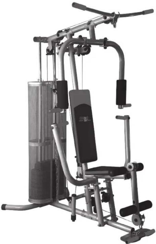
natural_image
Exterior view of a modern gym machine with adjustable arms and legs (no visible text or symbols)D
Assembly and exercise instructions for Order No.
F
text_image
Technical schematic diagram of a mechanical device with numbered components and labeled partstext_image
Technical diagram of a mechanical assembly with numbered components and labeled partsSCHRITT 2:
text_image
Technical diagram of a stationary exercise machine with numbered components and labeled partsSCHRITT 3:
text_image
Technical diagram of a mechanical assembly with numbered parts and an inset view showing two circular components labeled 22 and 23.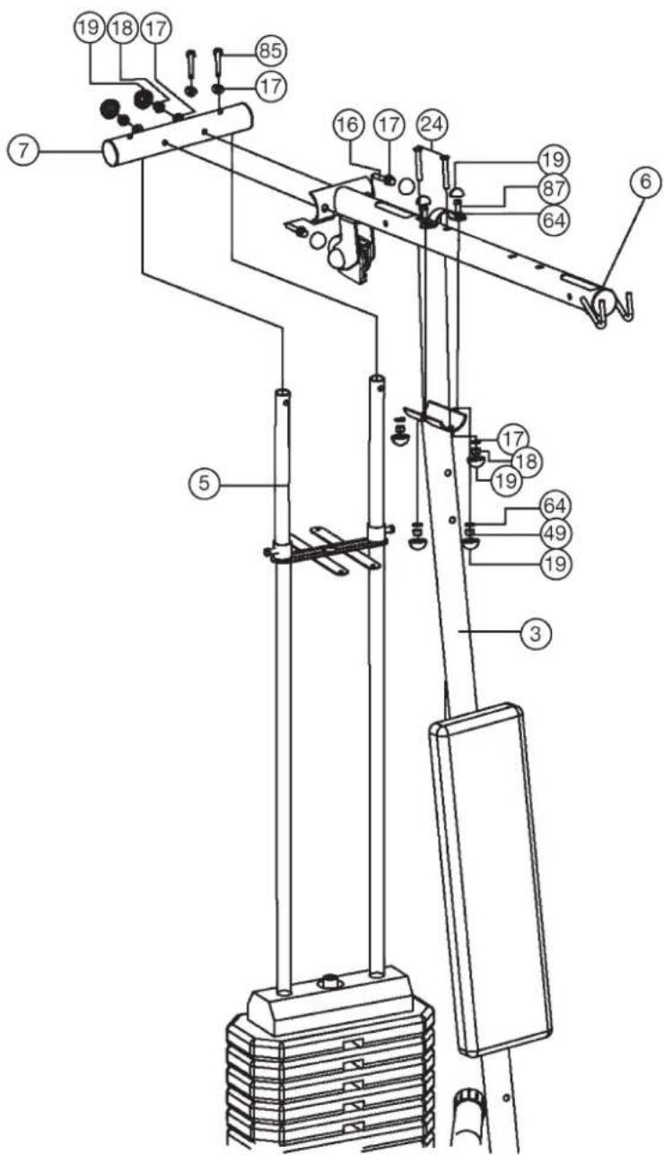
text_image
Technical diagram of a mechanical device with numbered components for identificationtext_image
Technical diagram of a mechanical device with numbered components and exploded view, likely for assembly or maintenance instructions.text_image
Technical diagram of a mechanical device with numbered components for identification
text_image
Technical diagram of a mechanical device with numbered components and labeled parts, likely for assembly or maintenance instructions.SCHRITT 6:
text_image
Technical diagram of a mechanical exercise machine with numbered components and labeled partstext_image
Technical diagram of a mechanical exercise machine with numbered components for identificationtext_image
Technical diagram of a mechanical device with numbered components and an inset view labeled with part numbers.SCHRITT 9:
text_image
Technical diagram of a mechanical lifting device with numbered components and exploded view viewsSCHRITT 11:
natural_image
Diagram of a mechanical clamp or spring with a coiled spring and labeled part (74), no text or symbols present.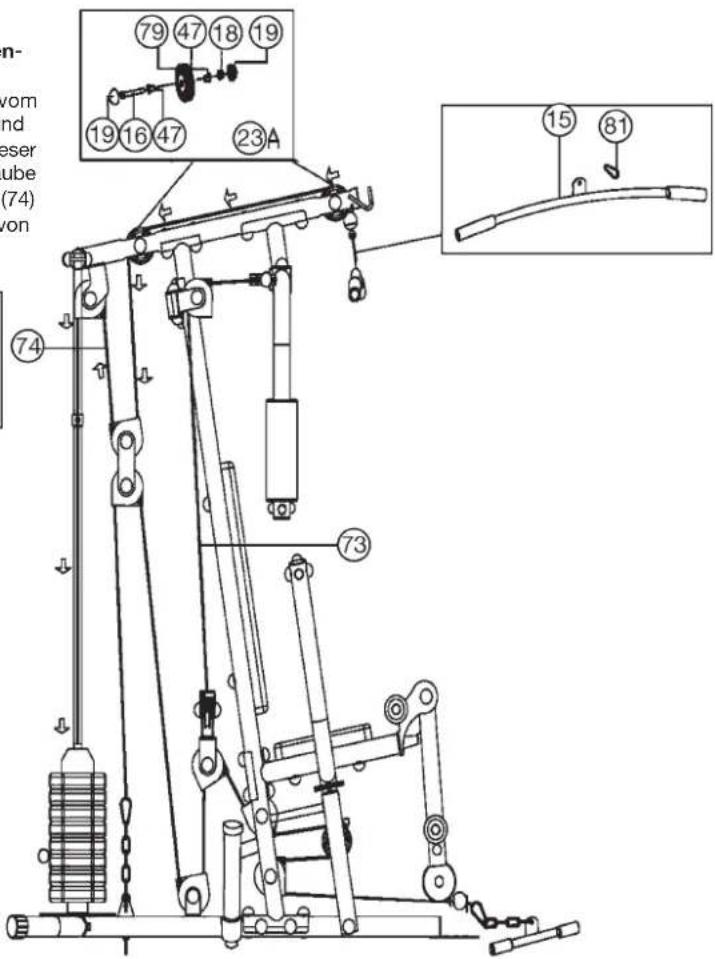
text_image
79 47 18 19 19 16 47 23A ⑦4 ⑦3 ⑮ ⑧1SCHRITT 12:
text_image
Technical diagram of a mechanical exercise machine with numbered components and labeled parts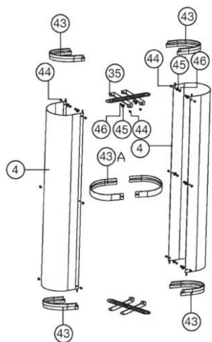
text_image
Technical diagram of a mechanical assembly with numbered components and labeled partsSCHRITT 13:
Kontrolle:
natural_image
Technical line drawing of a mechanical device with pipes and actuators (no text or symbols)Trainingsanleitung
natural_image
Person seated in a fitness machine, viewed from the side (no text or symbols visible)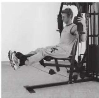
natural_image
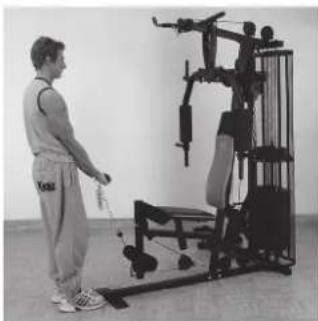
Person performing a seated leg exercise using a resistance bar machine (no visible text or symbols)Übung 3
Überzug, Pull over, Pull over, Trekoefening
natural_image
Person performing a seated exercise on a gym machine (no visible text or symbols)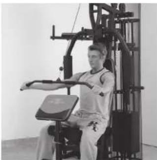
natural_image
Person performing a seated exercise using a leg press machine (no visible text or symbols)Übung 5
Arm curl, Arm curl, Bras curl, Arm curl
natural_image
Person using a leg exercise machine in a gym (no visible text or symbols)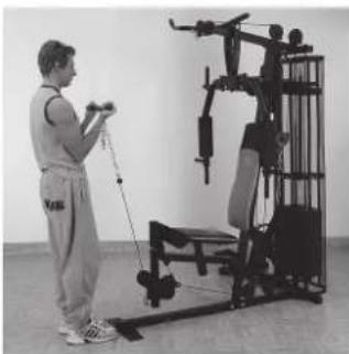
natural_image
Person using a leg exercise machine in a gym (no visible text or symbols)Übung 7
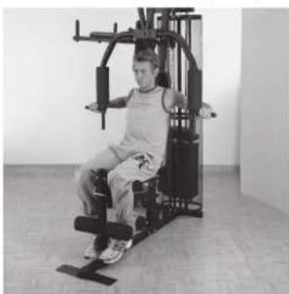
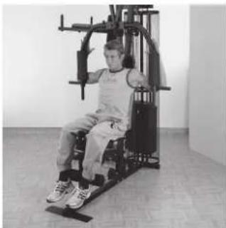
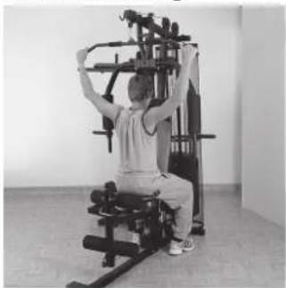
Bankdrücken, Benchpress, Développé-assis, Bankdrukken
natural_image
Person seated in a gym machine, no visible text or symbols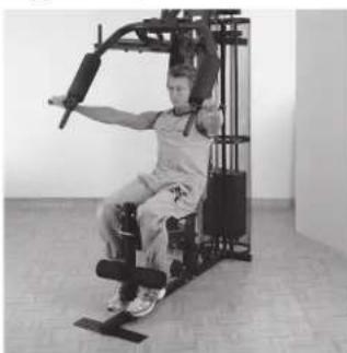
natural_image
Person performing a seated exercise using a resistance band machine (no visible text or symbols)Übung 9
Butterfly, Butterfly, Butterfly, Butterfly
natural_image
Person seated in a fitness machine with arms extended, no visible text or symbols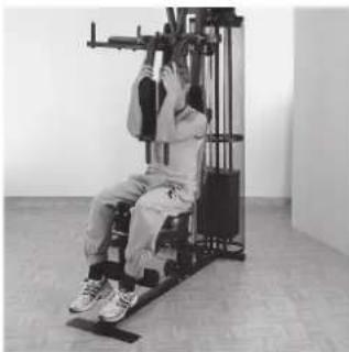
natural_image
Person using a leg exercise machine in a gym (no visible text or symbols)Übung 2
Beinbeugen, Leg Curl, Flexion des jambes, Beenbuigen
natural_image
Person performing a fitness exercise using a leg press machine (no visible text or symbols)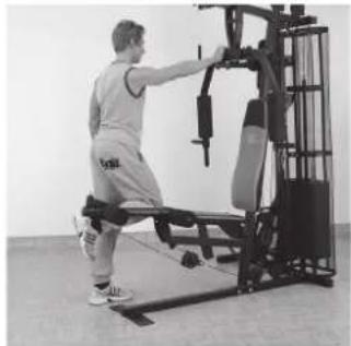
natural_image
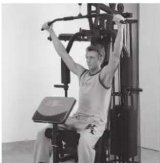
Person using a Pilates reformer machine in a gym (no visible text or symbols)Übung 4
Latissimuszug, Latissimus Pull, Traction latissimus, Latissimusofening
natural_image
Person using a leg exercise machine in a gym (no visible text or symbols)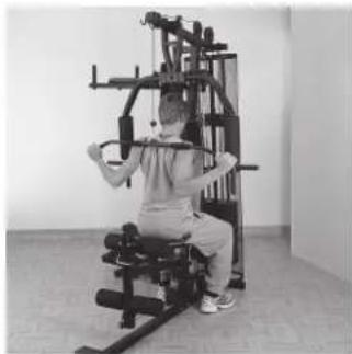
natural_image
Person seated in a resistance exercise machine, performing a handstand (no visible text or symbols)Übung 6
natural_image
Person standing next to a fitness equipment setup (no visible text or symbols)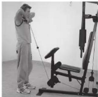
natural_image
Person using a leg exercise machine in a gym (no visible text or symbols)Übung 8
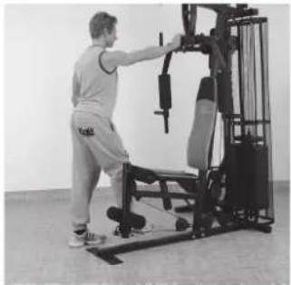
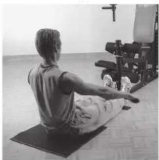
Rudern, Rowing, Rameur bas, Roeien
natural_image
Person performing seated exercise on yoga mat in gym (no visible text or symbols)
natural_image
Person sitting on a mat in a gym, using an armchair on the floor (no visible text or symbols)- Important Recommendations and Safety Information Page 17
- Summary of Parts Page 3
- Parts List Page 18 - 19
- Assembly Instructions With Exploded Diagrams Page 20 - 28
- Training Instructions Page 28
- Taining Types
Dear customer,
We congratulate you on your purchase of this home training sports unit and hope that we will have a great deal of pleasure with it. Please take heed of the enclosed notes and instructions and follow them closely concerning assembly and use.
Please do not hesitate to contact us at any time if you should have any questions.
Important Recommendations and Safety Information
Our product has been tested by TÜV-GS and meets the latest and toughest safety standards. This fact does not however mean that you can fail to closely observe the following basic points:
- Assemble the equipment according to the assembly instructions and only use the individual parts enclosed for assembly of the equipment and which are listed in the parts list as being specifically for this equipment. Before you start assembly, check against the delivery to make sure that everything has been delivered, and check against the packing list to make sure all the parts have been enclosed.
- Check before the equipment is first used, and again at regular intervals, that all screws, bolts, nuts and other connections have been done up tightly, to ensure that your training equipment is in a safe operating condition at all times.
- Place the equipment on a dry, level surface and protect it against damp and wetness. If you wish to protect the area underneath the equipment against damage from pressure or from becoming dirty or the like, we recommend that you place a suitable non-slip item under the equipment (such as a rubber mat or sheet of wood).
- Always wear training clothing and shoes that are suitable for fitness training when you are doing training work on the equipment. The clothing must be of a type that will not hang down during training due to its shape (e.g., length). Shoes should be selected for their suitability when using the training equipment, primarily so that they provide a secure grip for the foot and have a non-slip sole.
- Remove any objects from a vicinity of 2 meters avound the equipment before you start any training work.
- In general, you should consult your doctor before starting targeted training work. He can make a definitive statement as to the maximum exertion (pulse rate, wattage, duration of training, etc.) you can set for yourself and can also give you detailed information with respect to the correct body position during training, your training target, and questions of diet.
It is to take care that this item is not useable for therapeutic purpose. Exercise never after heavy meals. - Only carry out training work on the equipment when it is in perfect working order. Only use original spare parts in the event of a repair.
-
If it has not been explicitly stated otherwise in the instructions, the equipment may only be used by one person for training.
-
If you experience giddiness, nausea, chest pains or other abnormal symptoms, stop the training at once and see a doctor.
- In general, sports training equipment is not a toy. It may only be used in an appropriate manner and by persons who have been suitably informed or instructed.
- Children, invalids and the handicapped should only use the equipment in the presence of another person who can provide assistance and instruction.
- Always pay attention that you or any other persons never bring parts of the body in close proximity to any parts of the equipment that are still moving.
- When making settings for any adjustable parts, check that they are in the right position and also check the marked maximum setting.
- Do not use strong solvents for cleaning, and only use the tools supplied, or suitable ones of your own, for any repairs that may be required.
- Please dispose of the packaging and any parts that have to be replaced subsequently (all parts for the unit) at suitable collecting points or containers with a view to saving the environment.
- This machine has been tested and certified in compliance with EN 957-1 and -2 "H". The maximum permissible load (=body weight) is specified as 120 kg.
Parts List – Spare Parts List Fitness-Station SP 10 Order No.: 9986, 99861
Technical data: Release: 01.07.2012
Komplett Workout in a minimum of space Individual muscle training and strength exercising with much equipment
• 30 exercise possibilities
• Latissimus and curl bar
- Bench presses
- Leg curls
- Butterfly combinations
• Different rope exercises
- 8 push up weights of approx 5,6 kg = 45 kg weights
• Round steel tube ∅ 50 mm
- Load max. 120 kg (Body weight)
Space requirement L 146 x B 106 x H 191 cm
Please check after opening the packing that all the parts are without damaging there. Once you are sure that this is the case, you can start assembly.
Please contact us if any components are defective or missing, or if you need any spare parts or replacements in future:
Address: Top-Sports Gilles GmbH
Friedrichstr. 55
42551 Velbert
Telefon: +49 (0) 20 51 - 6 06 70
Telefax: +49 (0) 20 51 - 6 06 74 4
e-mail: info@christopeit-sport.com
www.christopeit-sport.com
| 0 | 5 | 10 | 15 | 20 | 25 | 30 | 35 | 40 | 50 | 60 | 70 | 80 | 90 | 100 mm |
| Part No. | Description | Dimension mm | Q'ty pcs | Attached to Part-No. | ET number 9986 | ET number 99861 |
| 1 | Main base | 1 | 2+3 | 33-9986-01-SI | 33-9986101-SW | |
| 2 | Rear stabilizer | 1 | 1 | 33-9986-02-SI | 33-9986102-SW | |
| 3 | Centre support | 1 | 1+6 | 33-9986-03-SI | 33-9986103-SW | |
| 4 | Weight Cover | 2 | 43 | 33-9986-04-SI | 33-9986104-SW | |
| 5 | Guide bars | 2 | 2+7 | 33-9986-05-SI | 33-9986105-SW | |
| 6 | Top cross beam | 1 | 3+7 | 33-9986-06-SI | 33-9986106-SW | |
| 7 | End Tube | 1 | 5+6 | 33-9986-07-SI | 33-9986107-SW | |
| 8 | Pulley holder | 1 | 3 | 33-9986-08-SI | 33-9986108-SW | |
| 9 | Butterfly holder | 1 | 6 | 33-9986-09-SI | 33-9986109-SW | |
| 10L | Butterfly arm left | 1 | 9 | 33-9986-10-SI | 33-9986110-SW | |
| 10R | Butterfly arm right | 1 | 9 | 33-9986-11-SI | 33-9986111-SW | |
| 11 | Bench press holder | 1 | 25 | 33-9986-12-SI | 33-9986112-SW | |
| 12 | Bench press arm | 2 | 11 | 33-9986-13-SI | 33-9986113-SW | |
| 13 | Seat support | 1 | 3 | 33-9986-27-SI | 33-9986114-SW | |
| 14 | Leg curler | 1 | 13 | 33-9986-15-SI | 33-9986115-SW | |
| 15 | Latissimus bar | 1 | 81 | 33-9986-16-SI | 33-9986116-SW | |
| 16 | Screw | M10 x 65 | 12 | 2+6+7+8+34+57 | 39-9982 | 39-9982 |
| 17 | Curve Washer | 10//22 | 36 | 16+21+24+76+77+91 | 39-10233-CR | 39-10233-CR |
| 18 | Nut | M 10 | 30 | 16+21+24+76+77+90+91 | 39-9981-VC | 39-9981-VC |
| 19 | Cap | for M10 | 72 | 16+18+21+24+76+77 | 36-9986-03-BT | 36-9986-03-BT |
| 20 | Washer | 10//20 | 33 | 16+21+24+76+77 | 39-9989-CR | 39-9989-CR |
| 21 | Screw | M10x60 | 4 | 10+12 | 39-10149 | 39-10149 |
| 22 | Cable slide | 22 | 23 | 36-9986-48-BT | 36-9986-48-BT | |
| 23 | Pulley | 11 | 1+3+8+11+55+56 | 36-9986-05-BT | 36-9986-05-BT | |
| 23A | Pulley | 3 | 6+14 | 36-9986-44-BT | 36-9986-44-BT | |
| 24 | Carriage Bolt | M10x60 | 6 | 1+6 | 39-10248 | 39-10248 |
| 25 | Axle | 1 | 1 | 33-9986-17-SI | 33-9986-17-SI | |
| 26 | Steel bearing | ∅ 12 | 10 | 1+10+11 | 36-9986-06-BT | 36-9986-06-BT |
| 26A | Steel bearing | ∅ 12 | 2 | 14 | 36-9986-46-BT | 36-9986-46-BT |
| 27 | Plastic stopper | ∅ 50 | 12 | 1+6+7+10-12+14 | 36-9986-07-BT | 36-9986-07-BT |
| 28 | Plastic stopper | 10//28 | 2 | 2 | 36-9986-08-BT | 36-9986-08-BT |
| 29 | Screw | M8x60 | 2 | 2 | 39-10436 | 39-10436 |
| 30 | Washer | 8//19 | 4 | 29 | 39-9962-CR | 39-9962-CR |
| 31A | Pulley block | 2 | 3 | 36-9986-09-BT | 36-9986-09-BT | |
| 32 | Curve plate | 1 | 3 | 33-9986-18-SI | 33-9986118-SW | |
| 33 | Cap | for M8 | 4 | 29 | 36-9986-43-BT | 36-9986-43-BT |
| 34 | Padded back | 1 | 3 | 36-9986101-BT | 36-9986101-BT | |
| 35 | Weight cover bracket | 2 | 4+5 | 33-9986-19-SI | 33-9986119-SW | |
| 36 | Rubber buffer | 2 | 5 | 36-9986-10-BT | 36-9986-10-BT | |
| 37 | Weight Plates | 7 | 5 | 36-9986-11-BT | 36-9986-11-BT | |
| 37A | Weight Plates | 1 | 39 | 36-9986-47-BT | 36-9986-47-BT | |
| 38 | Locking pin | 1 | 39 | 36-9986-12-BT | 36-9986-12-BT | |
| 39 | Weight disc bar | 1 | 74 | 33-9986-20-SI | 33-9986-20-SI | |
| 40 | Upper Weight | 1 | 39 | 33-9986-21-SI | 33-9986-21-SI | |
| 41 | Big washer | 13/45 | 1 | 37a | 36-9986-13-BT | 36-9986-13-BT |
| 42 | Fixing tube | 2 | 5 | 36-9986-14-BT | 36-9986-14-BT | |
| 43 | Weight cover support | 4 | 4 | 36-9986-15-BT | 36-9986103-BT | |
| 43a | Weigth cover support | 2 | 4 | 36-9986-16-BT | 36-9986104-BT | |
| 44 | Screw | M6x15 | 12 | 4+43 | 39-9860 | 39-9860 |
| Part Description No. | Dimension Q'ty mm | Attached to pcs | ET number ET Part-No. | number 9986 | 99861 | ||
| 45 Washer | 6//12 12 44 | 39-10007-CR | 39-10007-CR | ||||
| 46 | Nut | M6 | 12 | 44 | 39-9816-VC | 39-9816-VC | |
| 47 | Bushing | 4 | 6 | 36-9986-17-BT | 36-9986-17-BT | ||
| 48 | Screw | 3,5x15 | 2 | 42 | 39-9909 | 39-9909 | |
| 49 | Nut | M8 | 6 | 29+87 | 39-10031 | 39-10031 | |
| 50 | Pulley bracket | 2 | 8 | 36-9986-18-BT | 33-9986117-SW | ||
| 51 | Cap | for M12 | 12 | 52+54 | 36-9986-19-BT | 36-9986-19-BT | |
| 52 | Screw | M12x85 | 10 | 8+10+13 | 39-10316-SW | 39-10316-SW | |
| 53 | Washer | 12//24 | 8 | 52 | 39-10062 | 39-10062 | |
| 54 | Nut | M12 | 7 | 25+52 | 39-9986 | 39-9986 | |
| 55 | Double pulley holder | 1 | 72+74 | 36-9986-20-BT | 33-9986120-SW | ||
| 56 | Double pulley holder 90° | 1 | 72+73 | 36-9986-21-BT | 33-9986127-SW | ||
| 57 | Seat | 1 | 13 | 36-9986102-BT | 36-9986102-BT | ||
| 58 | Foam | 2 | 10 | 36-9986-22-BT | 36-9986-22-BT | ||
| 59 | Cap | 2 | 10L+10R | 36-9986-51-BT | 36-9986-51-BT | ||
| 60 | Foam | 8 | 15+62+86 | 36-9986-49-BT | 36-9986-49-BT | ||
| 61 | Cap | ∅ 25 | 16 | 15+62+70+80+86 | 39-10146 | 39-10146 | |
| 62 | Round tube | ∅ 25 | 4 | 10+12 | 33-9986-22-SI | 33-9986122-SW | |
| 63 | Inner hex screw | M8x25 | 2 | 11 | 39-10455 | 39-10455 | |
| 64 Washer | 8//16 10 87 | 39-9962-CR | 39-9962-CR | ||||
| 65 | Washer | 8,5//50 | 2 | 63 | 39-10500 | 39-10500 | |
| 66A | Pulley block | 1 | 11 | 36-9986-24-BT | 36-9986-24-BT | ||
| 67 | Foam | 4 | 70+80 | 36-9986106-BT | 36-9986106-BT | ||
| 68 | Rubber stop | 1 | 13 | 36-9986-26-BT | 36-9986-26-BT | ||
| 69 | Rubber pad | 1 | 3 | 36-9986-27-BT | 36-9986-27-BT | ||
| 70 | Round tube | 1 | 13 | 33-9986-23-SI | 33-9986123-SW | ||
| 71 | Chain | 9 + 3 | 2 | 72+81 | 36-9986-28-BT | 36-9986-28-BT | |
| 72 | Cable 1 leg curl | 3840mm | 1 | 1+14+11+56+71 | 36-9986-29-BT | 36-9986-29-BT | |
| 73 | Cable 2 butterfly | 2790mm | 1 | 10+56 | 36-9986-30-BT | 36-9986-30-BT | |
| 74 | Cable 3 latissimus | 3120mm | 1 | 6+39+55 | 36-9986-31-BT | 36-9986-31-BT | |
| 75 | Washer | 10//28 | 6 | 76+77 | 39-9991 | 39-9991 | |
| 76 | Screw | M10 x 95 | 2 | 3 | 39-10451-CR | 39-10451-CR | |
| 77 | Screw | M10 x 100 | 1 | 11 | 39-10452-CR | 39-10452-CR | |
| 78 | Bush | 3 | 76+77 | 36-9986-33-BT | 36-9986-33-BT | ||
| 80 | Short round tube | 1 | 14 | 33-9986-24-SI | 33-9986124-SW | ||
| 81 | Catch | 5 | 15+71+86 | 39-9822 | 39-9822 | ||
| 82 | Middle stabilizer | 1 | 3 | 33-9986-25-SI | 33-9986125-SW | ||
| 83 | Curve plate | 1 | 3 | 33-9986-26-SI | 33-9986126-SW | ||
| 85 | Bolt | M10x25 | 2 | 7 | 39-10052 | 39-10052 | |
| 86 | Curl bar | 1 | 81 | 36-9986-36-BT | 36-9986-36-BT | ||
| 87 | Bolt | M8x20 | 4 | 3+6+9 | 39-10041 | 39-10041 | |
| 88 | Assembly instruction | 1 | 36-9986-50-BT | 36-9986-50-BT | |||
| 89A | Pulley block | 1 | 14 | 36-9986-38-BT | 36-9986-38-BT | ||
| 90 | Screw | M10x45 | 9 | 1+6+50+55+56+89A | 39-10131-CR | 39-10131-CR | |
| 91 | Screw | M10x70 | 6 | 3+82 | 39-10148 | 39-10148 | |
| 92 | Rubber stop | 2 | 82 | 36-9986-45-BT | 36-9986-45-BT | ||
| 93 | Tool Set | 1 | 36-9986-39-BT | 36-9986-39-BT | |||
Instructions for assembly
Before you start assembly, it is essential that you follow our recommendations
and safety instructions. Take out all parts out of the carton and place them separately on the floor. Some parts are pre-assembled.
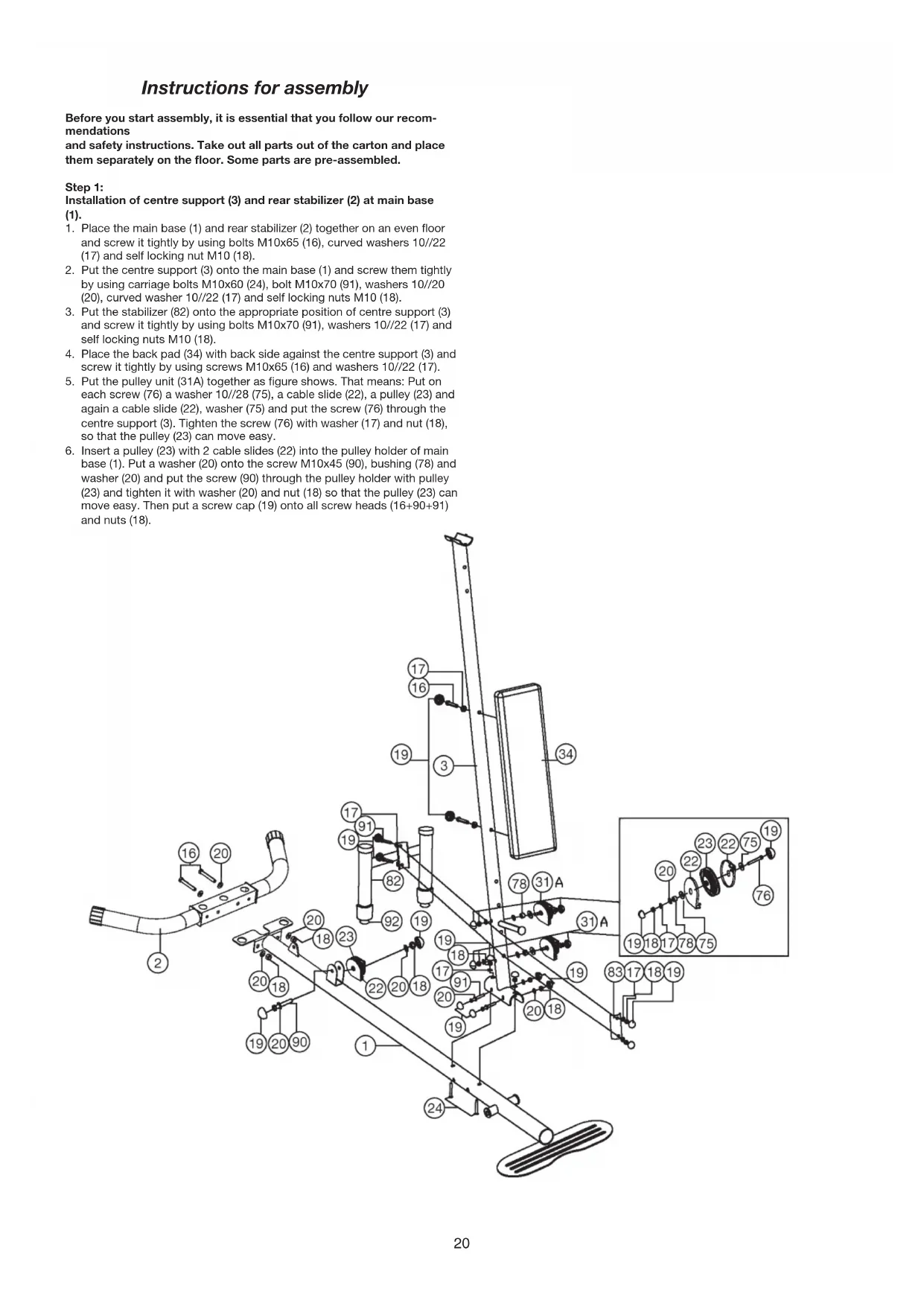
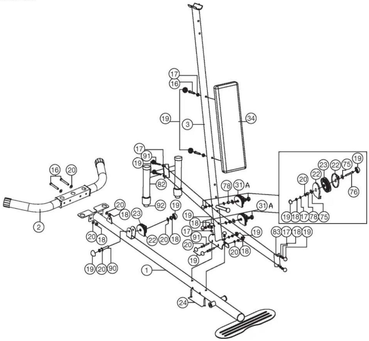
Step 1:
Installation of centre support (3) and rear stabilizer (2) at main base (1).
- Place the main base (1) and rear stabilizer (2) together on an even floor and screw it tightly by using bolts M10x65 (16), curved washers 10//22 (17) and self locking nut M10 (18).
- Put the centre support (3) onto the main base (1) and screw them tightly by using carriage bolts M10x60 (24), bolt M10x70 (91), washers 10//20 (20), curved washer 10//22 (17) and self locking nuts M10 (18).
- Put the stabilizer (82) onto the appropriate position of centre support (3) and screw it tightly by using bolts M10x70 (91), washers 10//22 (17) and self locking nuts M10 (18).
- Place the back pad (34) with back side against the centre support (3) and screw it tightly by using screws M10x65 (16) and washers 10//22 (17).
- Put the pulley unit (31A) together as figure shows. That means: Put on each screw (76) a washer 10//28 (75), a cable slide (22), a pulley (23) and again a cable slide (22), washer (75) and put the screw (76) through the centre support (3). Tighten the screw (76) with washer (17) and nut (18), so that the pulley (23) can move easy.
- Insert a pulley (23) with 2 cable slides (22) into the pulley holder of main base (1). Put a washer (20) onto the screw M10x45 (90), bushing (78) and washer (20) and put the screw (90) through the pulley holder with pulley (23) and tighten it with washer (20) and nut (18) so that the pulley (23) can move easy. Then put a screw cap (19) onto all screw heads (16+90+91) and nuts (18).
text_image
Technical diagram of a mechanical assembly with numbered components and labeled partsStep 2:
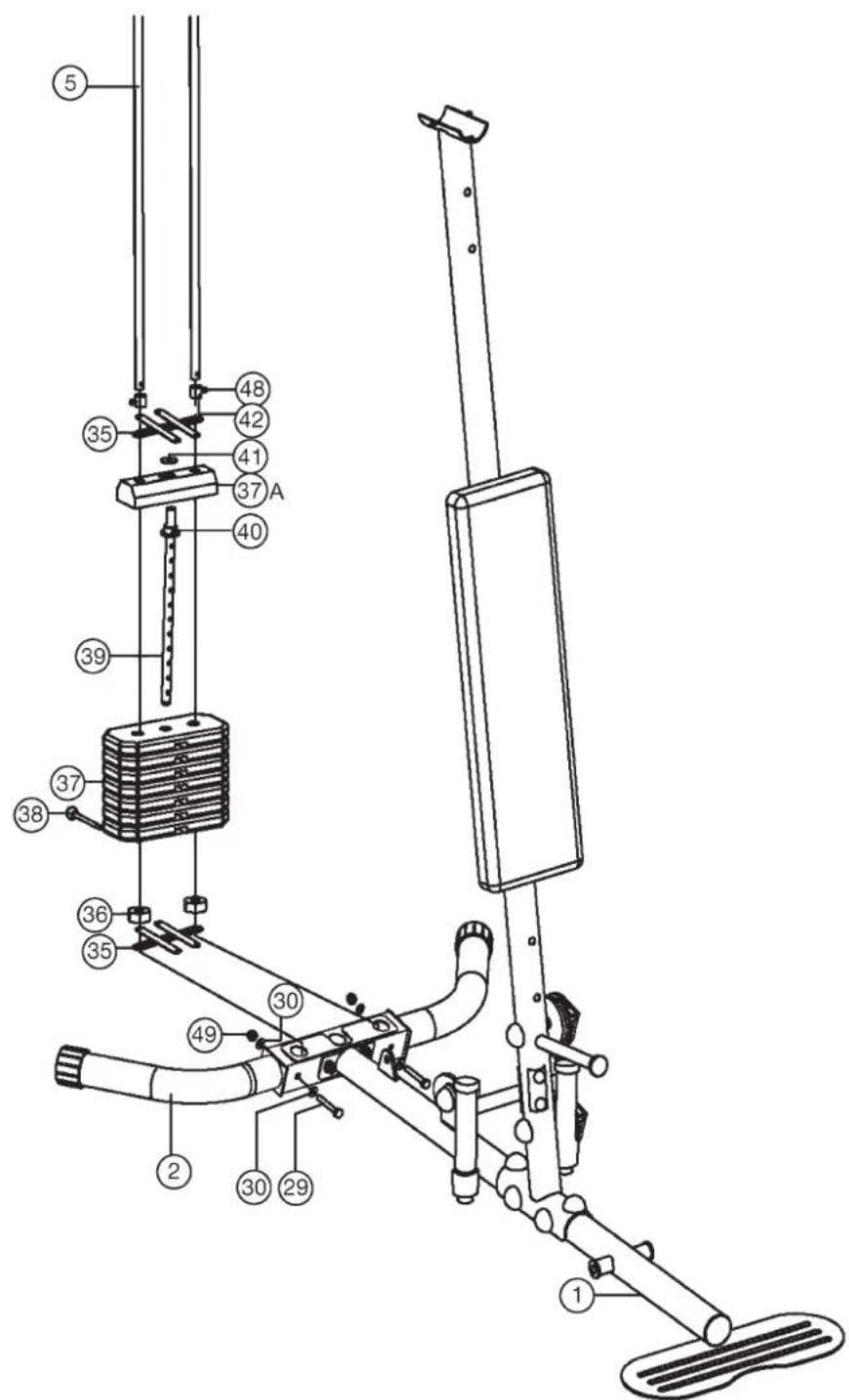
Installation of weight plates (37+40) and guide bars (5).
- Put the guide bars (5) (ends with holes) into the appropriate position of rear stabilizer (2) and secure them with screw M8x60 (29), curved washer 8//19 (30) and self locking nut M8 (49). Ensure that the screws are put through the holes of guide bars so that they are blocked in bottom position.
- Slide the weight cover bracket (35) onto the guide bars (5).
- Then put the rubber buffer (36) onto the guide bars (5).
- Place the 7 weights (37) onto the guide bars (5) as you can see on step drawing 2.
- Put the weight disc bar (39) (with upper plastic ring and cylinder) (40) into the weight plates (37) and put at least the smaller weight (37A) or
- Slide the second weight cover bracket (35) and the two fixing tubes (42) onto the guide bars (5) and place the big washer (41) onto the centre of upper weight pate (37A)
- To adjust the loaded weights use the weight selector bar (38) and put it into the weight disc bar (39) in desired position.
text_image
Technical diagram of a stationary exercise machine with numbered components and labeled partsStep 3:
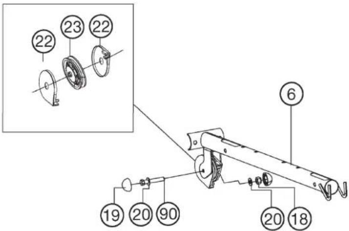
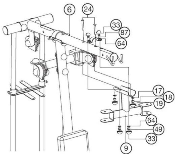
Installation of end tube (7) and top cross beam (6).
- Place the end tube (7) onto the ends of guide bars (5) and screw them together by using screw M10x25 (85) and curved washer 10//22 (17).
- Insert a pulley (23) with 2 cable slides (22) into the pulley holder of top cross beam (6). Put a washer (20) onto the screw M10x45 (90). Then put the screw (90) through the pulley holder with pulley (23) and tighten it with washer (20) and nut (18) so that the pulley (23) can move easy.
- Screw tightly the top cross beam (6) at end tube (7) by using screw M10x65 (16), curved washers10//22 (17) and nut (18). Then put a screw cap (19) onto all screw heads (16+21+87) and nuts (18).
- Put the top cross beam (6) in appropriate position onto the centre support (3) by using screw M8x20 (87), screw M10x65 (24), washers (17+64) and nut (18+49).
text_image
Technical diagram of a mechanical assembly with numbered parts and an inset view showing two circular components labeled 22 and 23.
text_image
Technical diagram of a mechanical device with numbered components for identificationStep 4:
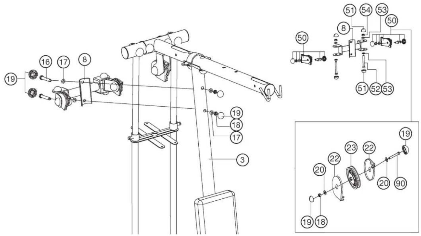
Installation of pulley holder (8) and pulley bracket (50).
- Place the pulley holder (8) in appropriate position at centre support (3) and screw these parts together by using screw M10x65 (16), curved washers 10//22 (17) and self locking nut M10 (18).
- Put the pulley bracket (50) into the pulley holder (8) and screw them together by using screw M12x85 (52), washer 12//24 (53) and self locking nut M12 (54). Attention, the cable pulley holder 1 (8) should turn easy when it is assembled. Then put a screw cap (51) onto all screw head (52) and nuts (54).
- Insert a pulley (23) with 2 cable slides (22) into each pulley bracket (50). Put a washer (20) onto the screw M10x45 (90). Then put the screw (90) through the pulley holder with pulley (23) and tighten it with washer (20) and nut (18) so that the pulley (23) can move easy. Then put a screw cap (19) onto all screw heads (16+21) and nuts (18).
text_image
Technical diagram of a mechanical device with numbered components and exploded view, likely for assembly or maintenance instructions.Step 5:
Installation of butterfly arm holder (9) and butter fly arms (10L+10R).
- Place the butterfly arm holder (9) in appropriate position at top cross beam (6), and tighten it firmly by using screw M8x20 (87), screw M10x60 (24), washers (17+64) and nut (18+49).
- Slide the foams (58) with help of a little bit soap water onto the butterfly arms (10L+10R).
- Place the butterfly arms (10L+10R) in right position into the appropriate holder of butterfly holder (9) and screw them together by using screw M12x85 (52), washer 12//24 (53) and self locking nut M12 (54). Then put a screw cap (51) onto all screw head (52) and nuts (54).
- Place the hand grips (62) into appropriate holder of butterfly arm left and right (10L+10R) and screw them tightly by using screw M10x60 (21), washer 10//22 (17) and nuts M10 (18). Then put the screw caps (19+33) onto all screw heads (21+87) and nuts (18+49).
text_image
Technical diagram of a mechanical device with numbered components for identification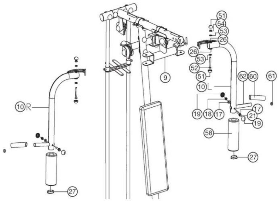
text_image
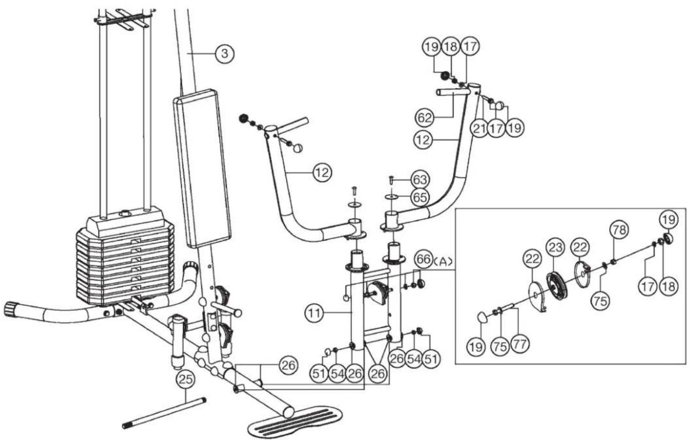
Technical diagram of a mechanical device with numbered components and labeled parts, likely for assembly or maintenance instructions.Step 6: Installation of bench press arms (12) and bench press arm holder (11).
- Place the bench press arm holder (11) at the appropriate holder of main base (1) and push the axle (25) through main base (1) and bench press arm holder (11). Secure the ends of axle (25) with nuts (54) and put a screw cap (51) on the nut (54).
- Put the bench press arms (12) onto the bench press arm holder (12) and tighten them by using screw M8x25 (63) and washer (65). The bench press arms (12) should move easy.
-
Place the hand grips (62) into appropriate holder of bench press arms (12) and screw them tightly by using screw M10x60 (21), washer 10//22 (17) and nuts M10 (18).
-
Put the pulley unit (66A) together as figure shows. That means: Put on screw M10x100 (77) a washer 10//28 (75), a cable slide (22), a pulley (23) and again, a cable slide (22), washer (75) and a bushing (78) and put the screw (77) through the bench press arm holder (11). Tighten the screw (77) with washer (20) and nut (18), so that the pulley (23) can move easy. Then put a screw cap (19) onto all screw heads (21+77) and nuts (18).
text_image
Technical diagram of a mechanical exercise machine with numbered components and labeled partsStep 7:
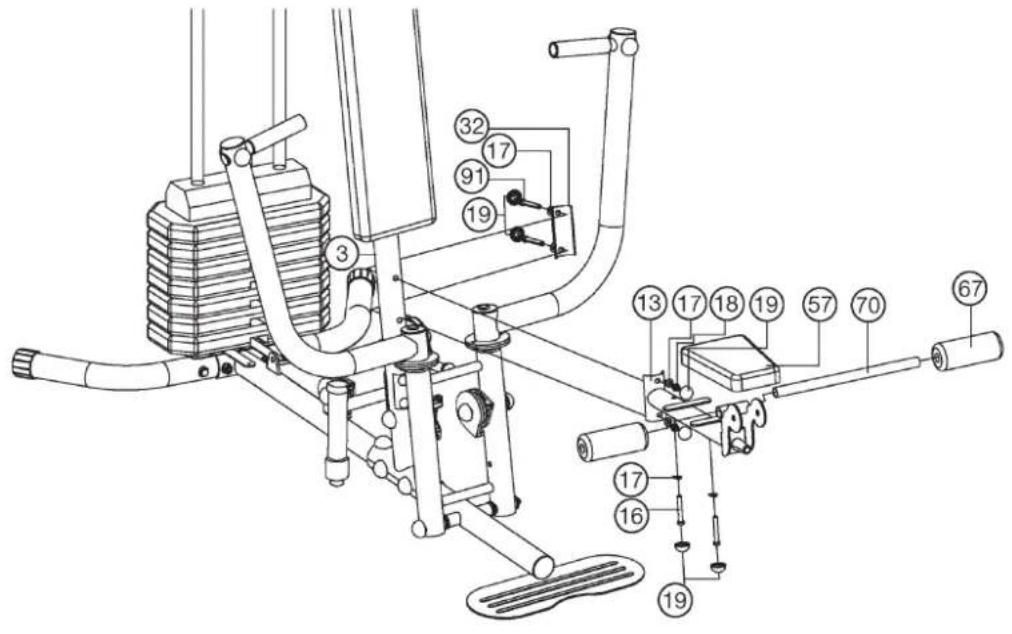
Installation of seat pad (57) and round tube (70) and seat support (13).
- Adjust the seat pad (57) on seat support (13) so that the threaded holes in the rear of seat pad (57) are align with the seat support (13) and screw it tightly by using screw M10x70 (91) and washer 10//22 (17).
- Slide the round tube (70) into the seat support (13) in middle position and slide two foams (67) onto the ends of round tube (70).
- Place the seat support (13) into appropriate holder of centre support (3) and screw it tightly by using screw M10x70 (91), washer 10//22 (17) and nuts M10 (18). Then put a screw cap (19) onto all screw heads (16+91) and nuts (18).
text_image
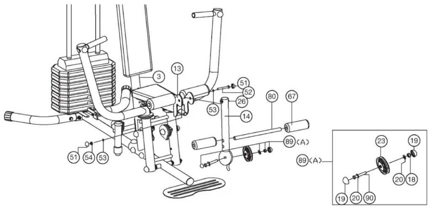
Technical diagram of a mechanical exercise machine with numbered components for identificationStep 8:
Installation leg curler (14) and short round tube (80).
- Put the leg curler (14) with pre-assembled steel bearings 1 (26) into the appropriate holder of seat support (13) and screw it tightly by using screw M12x85 (52) and self locking nut M12 (124). Attention, the leg curler (14) should move easy when it is assembled. Then put a screw cap (51) onto all screw head (52) and nuts (54).
- Slide the short round tube (80) into the holder of leg curler (14) in middle position and slide two foams (67) onto the ends of short round tube (80).
- Put the pulley unit (89A) together as figure shows. That means: Insert a pulley (23A) into the pulley holder of leg curler (14). Put a washer (20) onto the screw M10x45 (90), put the screw (90) through the pulley holder with pulley (23A) and tighten it with washer (20) and nut (18) so that the pulley (23A) can move easy. Then put a screw cap (19) onto all screw heads (90) and nuts (18).
text_image
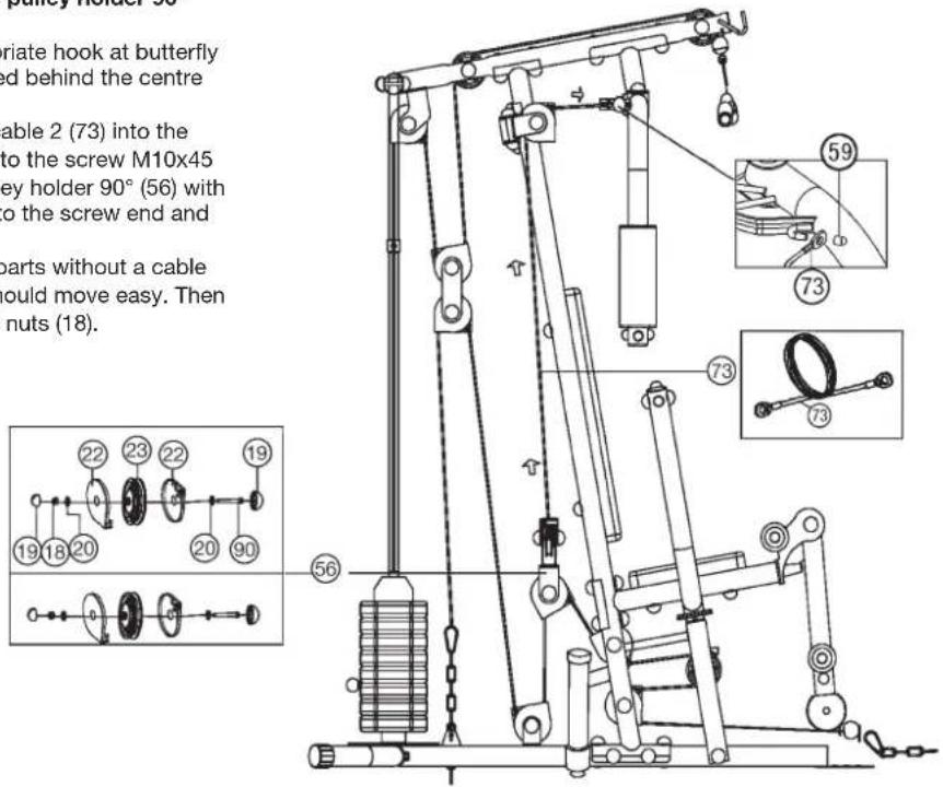
Technical diagram of a mechanical device with numbered components and an inset detailed view labeled with numbers and letters.Step 9: Installation of cable 2 for butterfly (73) with double pulley holder 90^ (56).
- Hang the both ends of cable 2 (73) into the appropriate hook at butterfly arm left and right (10L+10R) as figure shows (leaded behind the centre support (3)) and secure with end caps (59).
- Insert one pulley (23) with 2 vavle slides (22) with cable 2 (73) into the double pulley holder 90° (56). Put a washer (20) onto the screw M10x45 (90) and put the screw (90) through the double pulley holder 90° (56) with pulley (23) and put a washer (20) and a nut (18) onto the screw end and tighten it.
- Now install the second pulley (23) with necessary parts without a cable at double pulley holder 90° (56). The pulleys (23) should move easy. Then put a screw cap (19) onto all screw heads (90) and nuts (18).
text_image
pulley holder 56 riate hook at butterfly ed behind the centre able 2 (73) into the to the screw M10x45 key holder 90° (56) with to the screw end and parts without a cable would move easy. Then nuts (18). 56 19 18 20 22 23 22 19 59 73 73 73Step 10: Installation of cable 1 for leg curler (72) with double pulley holder (55).
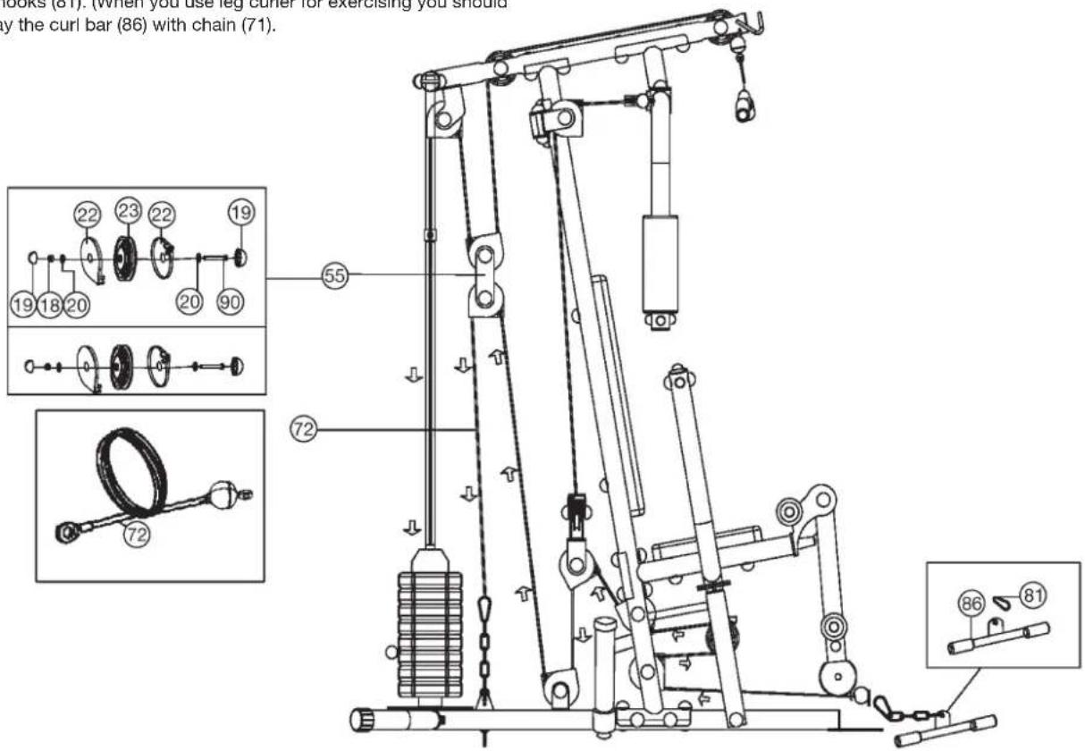
- Insert two pulleys (23) with 4 cable slides (22) into the double pulley holder (55). Put a washer (20) onto the screws M10x45 (90) and put the screw (90) through the double pulley holder (55) with pulleys (23). Place a washer (20) and nut (18) onto the screw ends and tighten them. The pulleys (23) should move easy. Then put a screw cap (19) onto all screw heads (21) and nuts (18).
- Pull cable 1 (72) with eye end through the leg curler (14) and around the pulleys as figure shows and connect the end of cable 1 (72) at appropriate holder on main base (1) by using chain (71) and carbine hooks (81).
- Connect the curl bar (86) at cable 1 (72) by using the chain (71) and carbine hooks (81). (When you use leg curler for exercising you should take away the curl bar (86) with chain (71).
text_image
lock (61). (When you use leg cutter for exercising you should by the curl bar (86) with chain (71). 22 23 22 19 19 18 20 20 90 55 72 72 86 81Step 11: Installation of cable 3 for latissimus (74) with double pulley holder (55).
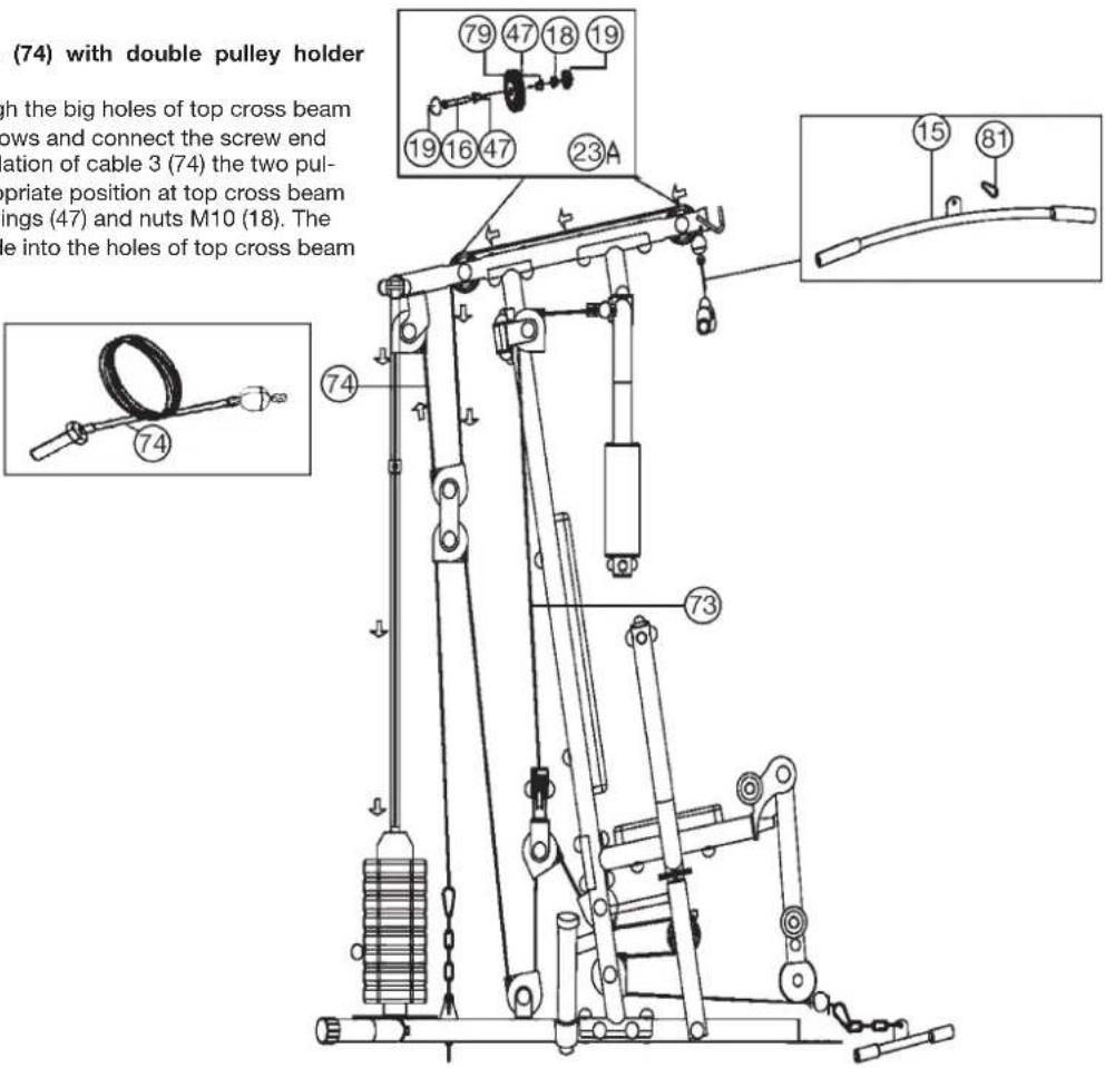
- Pull cable 3 (74) with screw end through the big holes of top cross beam (6) and around the pulleys as figure shows and connect the screw end with weight disc bar (39). During installation of cable 3 (74) the two pulleys (23A) have to assemble into appropriate position at top cross beam (6) by using screws M10x65 (16), bushings (47) and nuts M10 (18). The bushings (47) has to put from outer side into the holes of top cross beam (6).
(Note: To get a smooth sliding cable system, you may adjust the cable system at the chain (71) with carbine hooks (81) through setting them into another position or adjust the cable screw (74).)
- Connect the latissimus bar (15) at cable 3 (74) by using carbine hook (81). To storage the latissimus bar (15) you can put it on the appropriate holder in front of the top cross beam (6).
text_image
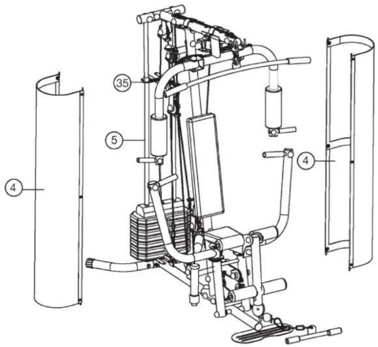
(74) with double pulley holder high the big holes of top cross beam rows and connect the screw end ation of cable 3 (74) the two pul- opriate position at top cross beam ings (47) and nuts M10 (18). The hole into the holes of top cross beam 79 47 18 19 19 16 47 23A 74 73 15 81Step 12: Installation of weight cover (4) with weight cover support (43+43a).
- Connect the weight cover support (43) on top and bottom side of weight cover (4). Then screw the weight cover support (43a) in the middle of weight cover (4) by using screw M6x15 (44), washer 6//12 (45) and nut M6 (46).
- Attach the weight cover (4) with pre-assembled weight cover supports (43+43a) to the weight cover bracket (35) and screw them tightly by using screw M6x15 (44), washer 6//12 (45) and nut M6 (46).
- Finally secure the fixing tube (42) on top of weight cover bracket (35) with screw (48).
text_image
Technical diagram of a mechanical device with numbered components, likely an exercise machine or exercise apparatus.
text_image
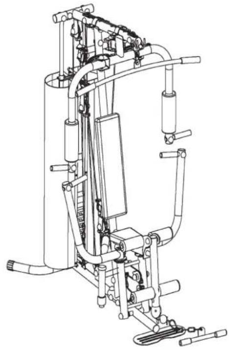
Technical diagram of a mechanical assembly with numbered components and labeled partsStep 13:
Checks:
- Check the correct installation and function of all screwed and plug connections. Installation is thereby complete.
- Before starting training, ensure that the recommended safety clearances are maintained to other objects.
- When everything is in order, familiarise yourself with the machine with light weights. The weights have to secure with locking pin (38). Maximum load of weight: 46Kg.
Securing the weights:
Whether one or more weights are applied: the weights must always be secured against falling. This is performed with the locking pin (38). Push on the locking pin (38) immediately below the weight.
natural_image
Technical line drawing of a mechanical exercise machine (no text or symbols)Training instructions
You must consider the following factors in determining the amount of training effort required in order to attain tangible physical and health benefits:
1. Intensity:
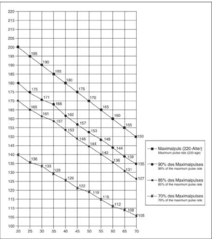
The level of physical exertion in training must exceed the level of normal exertion without reaching the point of breathlessness and / or exhaustion. A suitable guideline for effective training can be taken from the pulse rate. During training this should rise to the region of between 70% to 85% of the maximum pulse rate (see the table and formular for determination and calculation of this).
During the first weeks, the pulse rate should remain at the lower end of this region, at around 70% of the maximum pulse rate. In the course of the following weeks and months, the pulse rate should be slowly raised to the upper limit of 85% of the maximum pulse rate. The better the physical condition of the person doing the exercise, the more the level of training should be encreased to remain in the region of between 70% to 85% of the maximum pulse rate. This should be done by lengthening the time for the training and / or encreasing the level of difficulty. If the pulse rate is not shown on the computer display or if for safety reasons you wish to check your pulse rate, which could have been displayed wrongly due to error in use, etc., you can do the following:
a. Pulse rate measurement in the conventional way (feeling the pulse at the wrist, for example, and counting the number of beats in one minute).
b. Pulse rate measurement with a suitable specialised device (available from dealers specialising in health-related equipment).
2.Frequency
Most experts recommend a combination of health-conscious nutrition, which must be determined on the basis of your training goal, and physical training three times a week. A normal adult must train twice a week to maintain his current level of condition. At least three training sessions a week are required to improve one's condition and reduce one's weight. Of course the ideal frequency of training is five sessions a week.
3. Planning the training
Each training session should consist of three phases: the warm-up phase, the training phase, and the cool-down phase. The body temperature and oxygen intake should be raised slowly in the warm-up phase. This can be done with gymnastic exercises lasting five to ten minutes.
Then the actual training (training phase) should begin. The training exertion should be relatively low for the first few minutes and then raised over a period of 15 to 30 minutes such that the pulse rate reaches the region of between 70% to 85% of the maximum pulse rate.
In order to support the circulation after the training phase and to prevent aching or strained muscles later, it is necessary to follow the training phase with a cooldown phase. This should be consist of stretching exercises and / or light gymnastic exercises for a period of five to ten minutes.
4. Motivation
The key to a successful program is regular training. You should set a fixed time and place for each day of training and prepare yourself mentally for the training. Only train when you are in the mood for it and always have your goal in view. With continuous training you will be able to see how you are progressing day by day and are approaching your personal training goal bit by bit.
line
| X-axis | Maximalpuls (220-Aiter) Maximum pulse rate (220-age) | 90% des Maximalpulses 90% of the maximum pulse rate | 85% des Maximalpulses 85% of the maximum pulse rate | 70% des Maximalpulses 70% of the maximum pulse rate | |---|---|---|---|---| | 20 | 200 | 180 | 170 | 140 | | 25 | 195 | 175 | 165 | 136 | | 30 | 190 | 171 | 161 | 133 | | 35 | 185 | 166 | 157 | 129 | | 40 | 180 | 162 | 153 | 126 | | 45 | 175 | 157 | 148 | 122 | | 50 | 170 | 153 | 144 | 119 | | 55 | 165 | 148 | 140 | 115 | | 60 | 160 | 144 | 136 | 112 | | 65 | 155 | 139 | 131 | 108 | | 70 | 150 | 135 | 127 | 105 |Calculation formula: Maximum pulse rate = 220 - age (220 minus your age)
90% of the maximum pulse rate = (220 - age) x 0.9 85% of the maximum pulse rate = (220 - age) x 0.85 70% of the maximum pulse rate = (220 - age) x 0.7
F
Sommaire
text_image
Technical diagram of a stationary exercise machine with numbered components and labeled partstext_image
Technical diagram of a mechanical assembly with numbered parts and an inset view showing two circular components labeled 22 and 23.
text_image
Technical diagram of a mechanical device with numbered components for identificationtext_image
Technical diagram of a mechanical device with numbered components and exploded view, likely for assembly or maintenance instructions.text_image
Technical diagram of a mechanical device with numbered components for identification
text_image
Technical diagram of a mechanical device with numbered components and labeled parts, likely for assembly or maintenance instructions.text_image
Technical diagram of a mechanical exercise machine with numbered components and labeled partstext_image
Technical diagram of a mechanical exercise machine with numbered components for identificationtext_image
Technical diagram of a mechanical device with numbered components and an inset view showing labeled parts.text_image
Technical diagram of a mechanical lifting device with numbered components and exploded view viewsnatural_image
Mechanical tool with a coiled spring and labeled part (74), no text or symbols present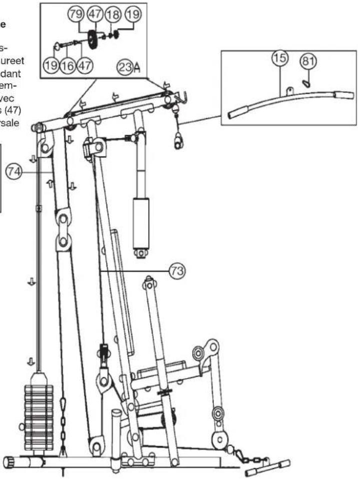
text_image
Technical diagram of a mechanical lifting device with numbered components and labeled partstext_image
Technical diagram of a mechanical exercise machine with numbered components and labeled parts
text_image
Technical diagram of a mechanical assembly with numbered components and labeled partsEtape 13:
Controle :
natural_image
Technical line drawing of a mechanical device with pipes and actuators (no text or symbols)text_image
Technical diagram of a mechanical assembly with numbered components and labeled partsStap 2:
text_image
Technical diagram of a stationary exercise machine with numbered components and labeled partsStap 3:
text_image
Technical diagram of a mechanical assembly with numbered parts and an inset view showing two circular components labeled 22 and 23.
text_image
Technical diagram of a mechanical device with numbered components for identificationStap 4:
text_image
Technical diagram of a mechanical device with numbered components for identification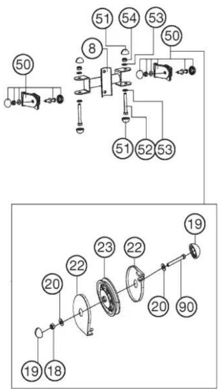
text_image
Technical diagram showing mechanical assembly with numbered components and labeled partsStap 5:
text_image
Technical diagram of a mechanical device with numbered components for identification
text_image
Technical diagram of a mechanical device with numbered components and labeled parts, likely for assembly or maintenance instructions.text_image
Technical diagram of a mechanical exercise machine with numbered components and labeled partstext_image
Technical diagram of a mechanical exercise machine with numbered components for identificationtext_image
Technical diagram of a mechanical device with numbered components and an inset view showing labeled parts.Stap 9:
text_image
Technical diagram of a mechanical exercise machine with numbered components and labeled parts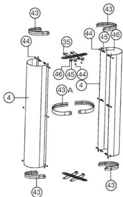
text_image
Technical diagram of a mechanical assembly with numbered components and labeled partsStep 13:
Controle:
natural_image
Technical line drawing of a mechanical device with no visible text or symbols3. Planning van de training
text_image
top Sports
© by Top-Sports Gilles GmbH
D-42551 Velbert (Germany)