GFD49ERPKDG - Tumble drier GE - Free user manual and instructions
Find the device manual for free GFD49ERPKDG GE in PDF.

User questions about GFD49ERPKDG GE
0 question about this device. Answer the ones you know or ask your own.
Ask a new question about this device
Download the instructions for your Tumble drier in PDF format for free! Find your manual GFD49ERPKDG - GE and take your electronic device back in hand. On this page are published all the documents necessary for the use of your device. GFD49ERPKDG by GE.
USER MANUAL GFD49ERPKDG GE
SAFETY INSTRUCTIONS .... 4
USING THE DRYER
Controls 6
Getting Started 7
Loading 11
Features....12
CARE AND CLEANING....13
INSTALLATION
INSTRUCTIONS....14
Reversing the door swing 33
Stacking 38
TROUBLESHOOTING TIPS ..... 42
CONSUMER SUPPORT
Warranty 46
Consumer Support 48
Write the model and serial numbers here:
Model # ____
Serial # ____
They are on the label on the front of the dryer behind the door.
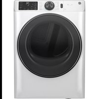
OWNER'S MANUAL & INSTALLATION INSTRUCTIONS
GFD49
GFD48
GFDR485
GFDR480
GHDS365
GHDS360
GFDR275
GFDR270
GFDS265
GFDS260
ENGLISH/FRANÇAIS/ ESPAÑOL
THANK YOU FOR MAKING GE APPLIANCES A PART OF YOUR HOME.
Whether you grew up with GE Appliances, or this is your first, we're happy to have you in the family.
We take pride in the craftsmanship, innovation and design that goes into every GE Appliances product, and we think you will too. Among other things, registration of your appliance ensures that we can deliver important product information and warranty details when you need them.
Register your GE appliance now online. Helpful websites and phone numbers are available in the Consumer Support section of this Owner's Manual. You may also mail in the pre-printed registration card included in the packing material.

GE APPLIANCES
IMPORTANT SAFETY INSTRUCTIONS

WARNING
To reduce the risk of fire, explosion, electric shock, or injury to persons when using your appliance, follow basic precautions, including the following:
- Read all instructions before using the appliance.
■ DO NOT dry articles that have been previously cleaned in, washed in, soaked in, or spotted with gasoline, dry-cleaning solvents, or other flammable or explosive substances, as they give off vapors that could ignite or explode.
■ DO NOT place items exposed to cooking oils in your dryer. Items contaminated with cooking oils may contribute to a chemical reaction that could cause a load to catch fire. To reduce the risk of fire due to contaminated loads, the final part of the tumble dryer cycle occurs without heat (cool down period). Avoid stopping a tumble dryer before the end of the drying cycle unless all items are quickly removed and spread out so that the heat is dissipated.
■ DO NOT allow children to play on or in this appliance. Close supervision of children is necessary when this appliance is used near children.
■ Before the appliance is removed from service or discarded, remove the door to the drying compartment.
■ DO NOT reach into the appliance if the drum is moving.
■ DO NOT install or store this appliance where it will be exposed to the weather.
■ DO NOT tamper with controls.
■ DO NOT repair or replace any part of this appliance or attempt any servicing unless specifically recommended in the user-maintenance instructions or in published user-repair instructions that you understand and have the skills to carry out.
■ DO NOT use fabric softeners or products to eliminate static unless recommended by the manufacturer of the fabric softener or product.
■ DO NOT dry articles containing foam rubber or similarly textured rubber-like materials.
■ Clean lint screen before or after each load.
■ DO NOT operate the dryer without the lint filter in place.
■ DO NOT store combustible materials, gasoline or other flammable liquids near the dryer. Keep area around the exhaust opening and adjacent surrounding areas free from the accumulation of lint, dust and dirt.
■ The interior of the appliance and exhaust duct should be cleaned periodically by qualified service personnel.
■ Unplug the appliance or turn off the circuit breaker before servicing. Pressing the Power or Start/Pause button DOES NOT disconnect power.
■ DO NOT operate this appliance if it is damaged, malfunctioning, partially disassembled, or has missing or broken parts, including a damaged cord or plug.
■ DO NOT spray any type of aerosol into, on or near dryer at any time. DO NOT use any type of spray cleaner when cleaning dryer interior. Hazardous fumes or electrical shock could occur.
■ See "ELECTRICAL CONNECTION" located in the Installation Instructions for grounding instructions.
SAVE THESE INSTRUCTIONS
Failure to follow safety warnings exactly could result in serious injury, death, or property damage.
- DO NOT store or use gasoline or other flammable vapors and liquids in the vicinity of this or any other appliance.
- WHAT TO DO IF YOU SMELL GAS:
- DO NOT try to light any appliance.
- DO NOT touch any electrical switch; DO NOT use any phone in your building.
- Clear the room, building, or area of any occupants.
- Immediately call your gas supplier from a neighbor's phone. Follow the gas supplier's instructions.
- If you cannot reach your gas supplier, call the fire department.
- Installation and service must be performed by a qualified installer, service agency, or the gas supplier.
State of California Proposition 65 Warnings
WARNING
This product contains one or more chemicals known to the State of California to cause cancer, and birth defects or other reproductive harm.
Gas appliances can cause low-level exposure to some of these substances, including benzene, carbon monoxide, formaldehyde, and soot, caused primarily by the incomplete combustion of natural gas or LP fuels. Exposure to these substances can be minimized by properly venting the dryer to the outdoors.
SAVE THESE INSTRUCTIONS
About the dryer control panel.
WARNING
To reduce the risk of fire, electric shock, or injury to persons, read the IMPORTANT SAFETY INSTRUCTIONS before operating this appliance.
Throughout this manual, features and appearance may vary from your model.
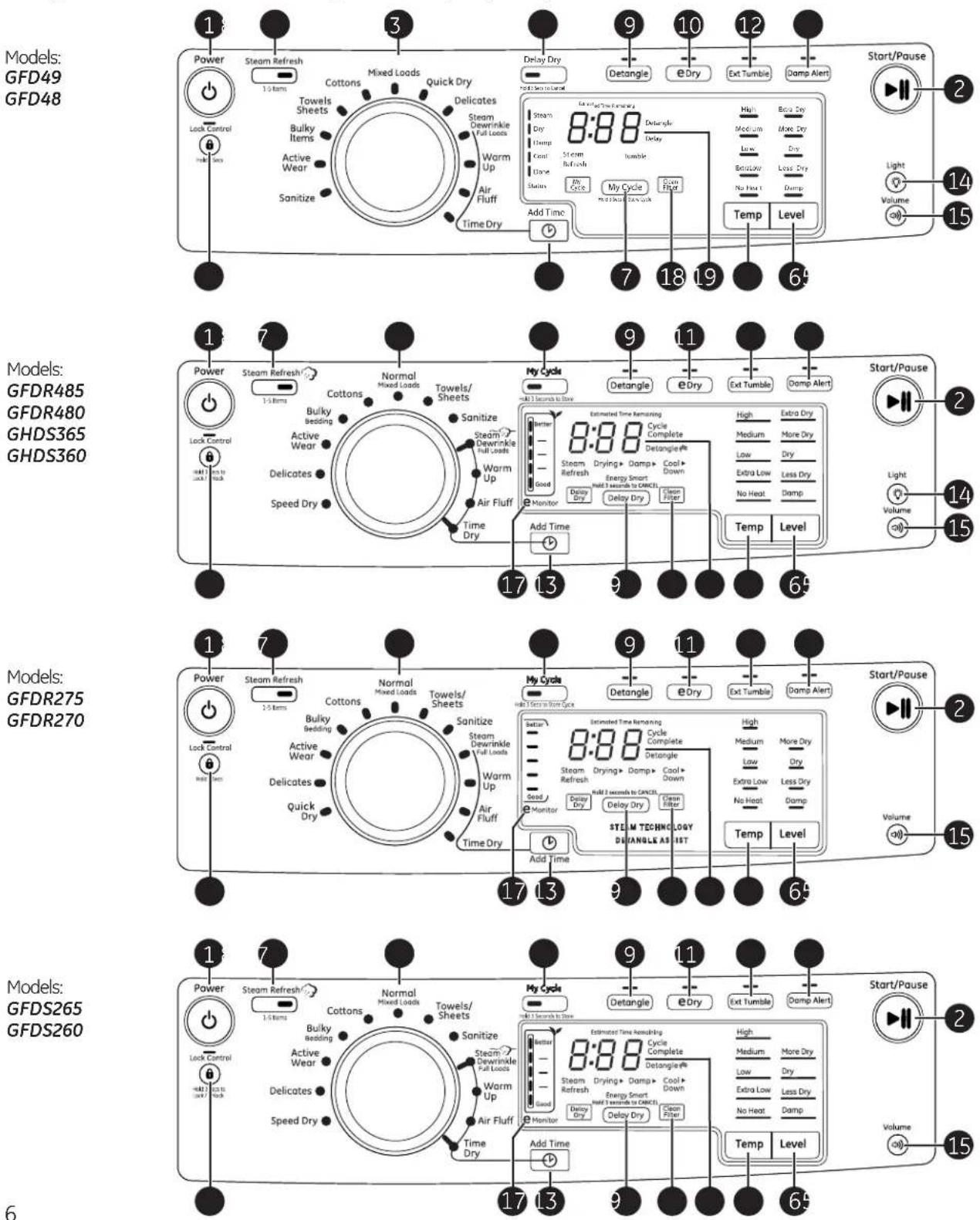
Models: GFD49 GFD48
Models:
GFDR485
GFDR480
GHDS365
GHDS360
Models: GFDR275 GFDR270
Models: GFDS265 GFDS260
Getting Started
1 Press the Power button.
If the screen is dark, a press of the Power button will "wake up" the display.

3 Press the Start/Pause button.

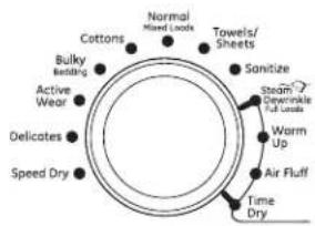
2 Select a dry cycle. (Defaults are set for each cycle. These default settings can be changed. See Control settings for more information.)
flowchart
graph TD
    A["Cottons"] --> B["Normal Mixed Loads"]
    B --> C["Towels/Sheets"]
    C --> D["Sanitize"]
    D --> E["Steam/Reversible Life"]
    E --> F["Worm Up"]
    F --> G["Air Fluff"]
    G --> H["Time Dry"]
    H --> I["Speed Dry"]
    I --> J["Delicates"]
    J --> K["Active Wear"]
    K --> L["Bulky Bedding"]
1 Power
Press to "wake up" the display. If the display is active, press to turn the dryer off. NOTE: Pressing Power does not disconnect the appliance from the power supply.
2
Start/Pause

Start/Pause
Press to start a dry cycle. If the dryer is running, press it once and it will pause the dryer. Press it again to resume the dry cycle.
3 Dry Cycles
The dry cycle controls the length and tumble speed of the drying process. The chart below will help you match the dry setting with the loads.
| Normal/Mixed Loads | For loads consisting of cottons and poly-blends. |
| Cottons | For cottons and most linens. NOTE: Energy Star® models are tested on Cottons with default settings. |
| Bulky/Bedding or Bulky Items | For large coats, bed spreads, mattress covers, sleeping bags, blankets, comforters, jackets, small rugs, and similar large and bulky items. |
| Active Wear | Clothing worn for active sports exercise and some casual wear. Fabrics include new technology finishes and stretch fibers such as Spandex. Also for clothing labeled Easy Care or Perma Press: For wrinkle-free and permanent press items. |
| Delicates | For lingerie and special-care fabrics. |
| Speed Dry or Quick Dry | For small loads that are needed in a hurry, such as sports or school uniforms. Can also be used if the previous cycle left some items damp, such as collars or waistbands. |
| Towels/Sheets | Use for towels OR sheets. It is not recommended to mix towels and sheets in the same load. |
| Sanitize | Reduces certain types of bacteria by 99.8%, including: Staphylococcus aureus, Pseudomonas aeruginosa, and Klebsiella pneumoniae. The antibacterial process occurs when high heat is used during a portion of this drying cycle. |
| Steam Dewrinkle Full Loads | Provides 20 minutes of steam drying to assist with dewrinkling clothes. Ideal for loads left in dryer for an extended time. |
| Warm Up | Provides 10 minutes of warming time to warm up clothes. |
| Air Fluff | Provides 10 minutes of tumbling time without heat. |
| Time Dry | Use to set your own dry time. Time Dry is also recommended for small loads. To use:1. Turn dry cycle dial to Time Dry.2. Increase the drying time by pressing the Add Time button.Note: This button only increases the time. When max time is reached, pressing the button again will reset the counter to the lowest setting.3. Select the Temp.4. Close the door.5. Press Start/Pause. |
Control settings.
| 4 | Add Time | Add TimePress to add time to theSteam Dewrinkle,Warm Up, Air Fluff or Time Drycycles in 10minute increments. | |
| 5 | Temp | TempYou can change the temperature of your drycycle. | |
| HighFor regular to heavy cottons. | |||
| MediumForsynthetics, blends and items labeled Permanent Press. | |||
| LowFor delicates, synthetics and items labeled Tumble Dry Low. | |||
| Extra LowFor lingerie and special-care fabrics. | |||
| No HeatThis option may only be used withAir Fluff, in which items are tumbled withoutheat. | |||
| 6 | Level | LevelThe sensor continuously monitors the amount ofmoisture in the load. When the moisture in yourclothes reaches your selected dry level, the dryerwill stop. | NOTE: Sensor dryLevelonly works withCottons, Normal, Active Wear, Delicates,Speed Dry, Bulky, Towels/Sheets, SanitizeandSteam Dewrinklecycles. |
| Extra Drylon some models!Use for heavy-duty fabrics or items that should be very dry, such as towels. | |||
| More DryUse for heavy or mixed type of fabrics. | |||
| DryUse for normal dryness level suitable for most loads. This is the preferred cycle for energysaving. | |||
| Less DryUse for lighter fabric (ideal for ironing). | |||
| DampFor leaving items partially damp. | |||
| 7 | My CycleHold 3 Seconds to StoreMy CycleHold 3 Secs to Store Cycle(Dependingon model) | My CycleSet up your favorite combination of settingsand save them here for one touch recall. Thesecustom settings can be set while a cycle is inprogress.To store a My Cycle combination of settings:1. Select your drying cycle.2. ChangeTempandLevelsettings to fit yourneeds. | 3. Select any drying options you want.4. Press and hold theMy Clecebutton for 3seconds to store your selection. A beep willsound and the button will light up.To recall your stored My Cycle combination:Press theMY CYCLEbutton before drying aload.To change your stored My Cycle combination:Repeat steps 1-4. |
| 8 |  | Steam Refresh CycleFor slightly wrinkled dry garments. Significantly reduces wrinkles on up to 5 garments. After theSteam RefreshCycle, the unit will beep and display "0:00." If the unit is not turned off or if the door is not opened, the dryer will continue to tumble for 30 minutes. At the end of 30 minutes, it will display "0:00" and the cycle will be complete. | NOTE:A single extremely light fabric item may need to have an additional item included to achieve optimum results. |
| 9 |  | Detangle (on some models)Activates alternating forward and reverse tumbling to reduce tangling, dry more evenly, and improve drying times. Typical loads such as bed and bath mixed loads, where sheets, towels and pillow cases are laundered together, benefit from this capability. When the dryer reverses direction, there will be a slight pause and sound change. This is normal. | NOTE: Detangle is selected by default for Towels/ Sheets and Bulky/Bedding cycles. |
| 10 |  | eDryReduces the total energy consumption of specific dryer cycles by adjusting certain heat settings.NOTE: Cycle times will change when e-Dry is selected. | This cycle can be used withCottons, Normal, Active Wear, Delicates, Speed Dry, Bulky, Towels-Sheets, Sanitize and Steam Dewrinkle. |
| 11 |  | Extended TumbleMinimizes wrinkles by adding approximately 60 minutes of no-heat tumbling after clothes are dry. The beeper will sound every five minutes as a reminder to remove the clothes. | The estimated time remaining display will show "0:00".The extended tumble time does not get added to the cycle time on the display. |
| 12 |  | Damp AlertThis option causes the dryer to beep when clothes have dried to a damp level. Remove items that you wish to hang dry. TheDamp Alertwill only beep when this option is selected, and the dryer will continue to dry. | Removing clothes and hanging them when they are damp can reduce the need to iron some items. |
| 13 | 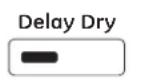 | Delay DryUse to delay the start of your dryer.1. Choose your dry cycle and any options.2. PressDelay Dry.You can change the delay time in 1 hour increments, using theDelay Drybutton.3. Press theStart/Pausebutton to start the countdown. | NOTE: If the door is opened while the dryer is in Delay Dry, the countdown time will not restart unless the door is closed andStart/Pausebutton has been pressed again. |
Control settings.
| 14 | Light | Light (on some models)Press the button to turn on the light in the dryer.Press the button again to turn the light off. | This only controls the light when the door is shut.NOTE: The light will turn off by itself after one minute when the door is shut. |
| 15 | Volume | VolumeThis button has two functions:■ To change the loudness of the end of cycle signal, press the button as many times as needed to reach the desired volume. There are four sound levels including OFF. | ■ To turn the button sounds ON/OFF, press and hold the button for 3 seconds (on some models). |
| 16 | Lock Control Hold 3 Secs to Lock / Unlock Hold 3 Secs to Lock / Unlock | Lock ControlYou can lock the controls to prevent any selections from being made. Or you can lock or unlock the controls after you have started a cycle.Children cannot accidentally start the dryer by touching buttons with this option selected.To lock the dryer, press and hold the Lock Control button for 3 seconds. | To unlock the dryer controls, press and hold the Lock Control button for 3 seconds.A sound is made to indicate the lock/unlock status.The indicator light above the button will illuminate when the controls are locked.NOTE: The Power button can still be used when the machine is locked. |
| 17 | 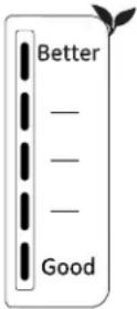 | eMonitor (on some models)The eMonitor lights display the relative energy use of your selected cycle and options. They are provided as an energy guide and range from Good (1 light) to Better (5 lights). Cycle (time), dryness level, temperature, and additional tumble options can increase or decrease your energy efficiency. Some cycles will not provide a display. | |
| Monitor | |||
| 18 |  | Clean Filter MessageThis message represents only a reminder and does not always appear when the filter needs cleaning. The filter should be cleaned after every drying cycle is complete. | This message will disappear after the Start/Pause button is pressed. Even though you may have already cleaned the filter (before or after the Power button has been pressed), the “Clean Filter” message will still be displayed until the Start/Pause button is activated. |
| 19 | 8:88 Cycle Complete Detangle®Steam Drying ▶ Damp ▶ Cool ▶ EnergySmart Down | DisplayDisplays the approximate time remaining until the end of the cycle.As the cycle begins, you will see an initial approximate total cycle time in the display. | Then lights will “race” in the display. This means the dryer is continuously monitoring the amount of moisture in the load. The lights will continue until the dryer senses a low level of moisture in the load. At that point, the dryer will calculate and display the approximate time remaining. |
Always follow the fabric manufacturer's care label when laundering.
Fabric Care Labels
Below are fabric care label "symbols" that affect the clothing you will be laundering.
Dry Labels
Tumble dry

Dry

Normal

Permanent Press/wrinkle resistant

Gentle/delicate

Do not tumble dry

Do not dry
lused with
do not wash)
Heat setting

High

Medium

Low

No heat/air
Special instructions

Line dry/ hang to dry

Drip dry

Dry flat

In the shade
Sorting and Loading Hints

WARNING

- Fire Hazard
- Keep flammable materials and vapors, such as gasoline, away from dryer.
- DO NOT dry anything that has ever had anything flammable on it (even after washing).
-
No washer can completely remove oil.
-
DO NOT dry anything that has ever had any type of oil on it (including cooking oils).
- Items containing foam, rubber, or plastic must be dried on a clothesline.
- Failure to do so can result in death, explosion, or fire.
As a general rule, if clothes are sorted properly for the washer, they are sorted properly for the dryer. Try also to sort items according to size. For example, do not dry a sheet with socks or other small items.
Do not add fabric softener sheets once the load has become warm. They may cause fabric softener stains. Bounce® Fabric Conditioner Dryer Sheets have been approved for use in this dryer when used in accordance with the manufacturer's instructions.
Do not overload. This wastes energy and causes wrinkling.
About dryer features.
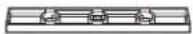
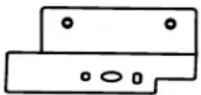
Rest rear legs on rear angled ledge
natural_image
Technical diagram of a mechanical assembly with no visible text or symbolsRest front legs on front angled ledge
Drying Rack (on some models)
A handy drying rack may be used for drying delicate items such as washable sweaters. Place items flat on the drying rack and block such items as wool sweaters and delicate fabrics. Dry with low heat.
To install the drying rack, extend the drying rack into the dryer drum. Rest the front two legs on the front angled ledge and then rest the rear two legs on the rear angled edge.
NOTES:
■ The drying rack is designed for use with the Time Dry cycles. Use with sensor cycles may result in damp items or extended cycle times.
■ Do not use this drying rack when there are other clothes in the dryer, that are not placed on the rack.
■ The drying rack, WE01X22274, is available as an accessory. Order on-line at GEApplianceParts.com, 24 hours a day or by phone at 877.959.8688 during normal business hours.
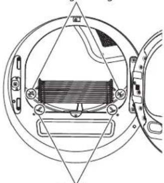
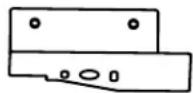
natural_image
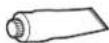
Technical line drawing of a mechanical assembly with circular components and internal components (no text or symbols)The Exterior: Wipe or dust any spills or washing compounds with a damp cloth. Dryer control panel and finishes may be damaged by some laundry pretreatment soil and stain remover products. Apply these products away from the dryer. The fabric may then be washed and dried normally. Damage to your dryer caused by these products is not covered by your warranty.
The Lint Filter: Clean the lint filter before each use.
Pull out the lint filter. Moisten your fingers and remove the captured lint. Once clean, slide the filter back into position. Have a qualified technician vacuum the lint from the dryer once a year.
NEVER OPERATE THE DRYER WITHOUT ITS FILTER IN PLACE.
Stainless Steel: To clean stainless steel surfaces use a damp cloth with a mild, non-abrasive cleaner suitable for stainless steel surfaces. Remove the cleaner residue and then dry with a clean cloth.
The stainless steel used to make the dryer drum provides the highest reliability available in a GE Appliances dryer. If the dryer drum should be scratched or dented during normal use, the drum will not rust or corrode. These surface blemishes will not affect the function or durability of the drum.
Dryer Interior and Duct: The interior of the appliance and exhaust duct should be cleaned once a year by qualified service personnel.
The Exhaust Duct: Inspect and clean the exhaust ducting at least once a year to prevent clogging. A partially clogged exhaust can lengthen the drying time.
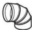
The Exhaust Hood: Check with a mirror that the inside flaps of the hood move freely when operating. Make sure that there is no wildlife (birds, insects, etc.) nesting inside the duct or hood.
natural_image
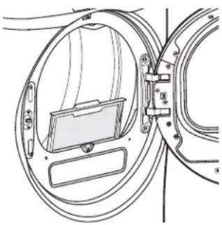
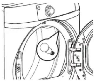
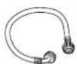
Technical line drawing of a washing machine handle and clasp mechanism (no text or symbols)Drum Lamp
(consumer replaceable on some models)
NOTE: The drum lamp is not consumer replaceable on models where there is a domed cover over an LED bulb. If this light should ever stop working, call for service.
For models that have a flat cover over the bulb secured by a screw:
Before replacing the light bulb, be sure to unplug the dryer power cord or disconnect the dryer at the household distribution panel by removing the fuse or switching off the circuit breaker. Reach above dryer opening from inside the drum to locate the light.
Remove the screw and the plastic cover to access the bulb. Replace with the appropriate bulb and then reaffix the cover and screw.
Order replacement bulb WE4M305 on-line at GEApplianceParts.com, by phone at 877.959.8688 during normal business hours, or purchase appliance bulb 7C7 from your local retailer.
The drum lamp turns on automatically when the dryer door is open. On some models, it can also be activated from the control panel.
Installation Instructions
Dry
Questions? Call GE Appliances at 800.GE.CARES (800.432.2737) or visit our Web site at: GEAppliances.com In Canada, call 1.800.561.3344 or visit www.GEAppliances.ca
BEFORE YOU BEGIN
Read these instructions completely and carefully.
- IMPORTANT – Save these instructions for local electrical inspector's use.
- IMPORTANT - Observe all governing codes and ordinances.
- Install the clothes dryer according to the manufacturer's instructions and local codes.
- Note to Installer – Be sure to leave these instructions with the Consumer.
- Note to Consumer – Keep these instructions for future reference.
- Clothes dryer installation must be performed by a qualified installer.
- This dryer must be exhausted to the outdoors.
- Before the old dryer is removed from service or discarded, remove the dryer door.
- Service information and the wiring diagram are located in the control console.
- Do not allow children on or in the appliance. Close supervision of children is necessary when the appliance is used near children.
- Proper installation is the responsibility of the installer.
- Product failure due to improper installation is not covered under the Warranty.
- Install the dryer where the temperature is above 50°F for satisfactory operation of the dryer control system.
- Remove and discard existing plastic or metal foil duct and replace with UL-listed duct.
WARNING

- Fire Hazard
- Clothes dryer installation must be performed by a qualified installer.
• Install the clothes dryer according to these instructions and local codes. - DO NOT install a clothes dryer with flexible plastic venting materials. If flexible metal (semi-rigid or foil-type) duct is installed, it must be UL-listed and installed in accordance with the instructions found in "Connecting the Dryer to House Vent" later in this manual. Flexible venting materials are known to collapse, be easily crushed and trap lint. These conditions will obstruct dryer airflow and increase the risk of fire.
- DO NOT install or store this appliance in any location where it could be exposed to water or weather.
- To reduce the risk of severe injury or death, follow all installation instructions.
- Save these instructions. (Installers: Be sure to leave these instructions with the customer.)
FOR GAS DRYERS ONLY
IN THE COMMONWEALTH OF MASSACHUSETTS, THE FOLLOWING INSTALLATION INSTRUCTIONS APPLY:
- Installation must be performed by a qualified or licensed contractor, plumber, or gasfitter qualified or licensed by the State.
- If using a ball valve, it shall be a T-handle type.
- A flexible gas connector, when used, must not exceed 3 feet.
UNPACKING YOUR DRYER
Tilt the dryer sideways and remove the foam shipping pads by pulling at the sides and breaking them away from the dryer legs. Be sure to remove all of the foam pieces around the legs.
Remove the bag containing the literature.
DRYER
DIMENSIONS
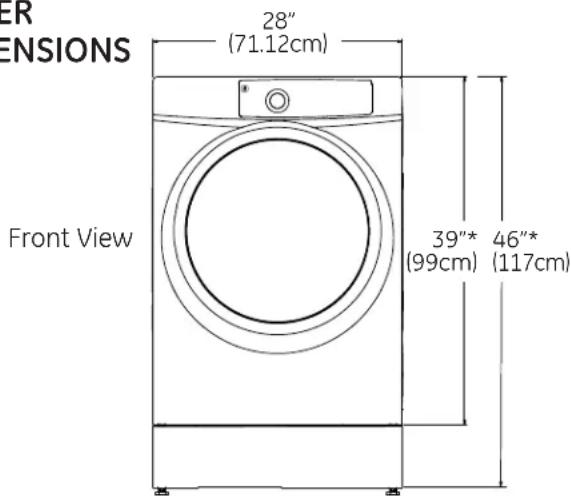
text_image
ER ENSIONS 28" (71.12cm) Front View 39"* 46"* (99cm) (117cm)*NOTE:
With Legs: 40 1/2" (102.5 cm) - (3/4" (1.9 cm) adjustability)
With Built-In Pedestal™: 46" (117 cm) - (3/4" (1.9 cm) adjustability)
With Optional Pedestal (GFXP1308): 52" (132.1 cm) - (3/4" (1.9 cm) adjustability)
Stacked: 78 1/4" (198.8 cm) - Not applicable for models with Built-In Pedestal™
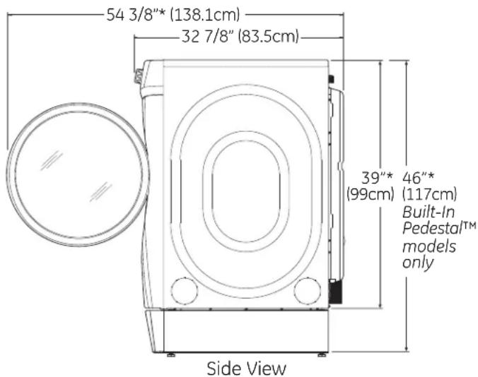
text_image
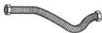
54 3/8"* (138.1cm) 32 7/8" (83.5cm) 39"* 46"* (99cm) (117cm) Built-In Pedestal™ models only Side ViewSTEAM WATER HOSES
GE Appliances strongly recommends the use of factory specified parts. These hoses are manufactured and tested to meet GE Appliances specifications.
GE Appliances strongly recommends the use of new water supply hoses. Hoses degrade over time and need to be replaced every 5 years to reduce the risk of hose failures and water damage.
Parts and Accessories
Order on-line at GEApplianceParts.com, 24 hours a day or by phone at 877.959.8688 during normal business hours.
| Part Number | Accessory |
| WE25X20060 | Complete Kit (hoses, Y-adapter washers) |
| OR | |
| WH41X10356 | Long Hose and |
| WH41X10357 | Short Hose |
POWER CORDS:
GE Appliances strongly recommends the use of factory specified parts. Select the power cord to fit your installation requirements.
| Part Number Type Length Amperage | |
| WX9X2 3-Prong 4 Feet 30 | |
| WX9X3 3-Prong 5 Feet 30 | |
| WX9X4 3-Prong 6 Feet 30 | |
| WX9X18 4-Prong 4 Feet 30 | |
| WX9X19 4-Prong 5 Feet 30 | |
| WX9X20 4-Prong 6 Feet 30 |
ACCESSORIES:
Order on-line at GEApplianceParts.com, 24 hours a day or by phone at 877.959.8688 during normal business hours.
| Part Number | Accessory |
| GFP1328SK | 28" width White Pedestal |
| GFP1328PK | 28" width Color Matched Pedestal |
| GEFLSTACK | Stacking Kit for Dryer over Washer |
| PM08X10085 | Flexible Metal Dryer Transition Duct |
| WE01X22274 | Clothes Dryer Shoe Rack |
REQUIREMENTS FOR ALCOVE OR CLOSET INSTALLATION

WARNING

- Explosion Hazard
Keep flammable materials and vapors, such as gasoline, away from dryer.
Place dryer at least 18" (46 cm) above the floor for a garage installation.
Failure to do so can result in death, explosion, or fire.
- The dryer MUST be vented to the outdoors.
- Minimum clearance between dryer cabinet and adjacent walls or other surfaces is:
0" either side
1" front and rear
1" top
- Consideration must be given to provide adequate clearance for installation and service.
- Closet doors must be louvered or otherwise ventilated and have at least 60 square inches of open area. If the closet contains both a washer and a dryer, doors must contain a minimum of 120 square inches of open area.
NOTE: WHEN THE EXHAUST DUCT IS LOCATED AT THE REAR OF THE DRYER, THE CONFIGURATION OF THE DUCTING MAY REQUIRE GREATER THAN 3" OF REAR CLEARANCE.
Gas Dryers Only:
- No other fuel burning appliance shall be installed in the same closet as a gas dryer.
- The dryer must be disconnected from the gas supply piping during pressure testing at pressures greater than 12 psi (3.5 kPa).
- A 1/8 inch NPT minimum plugged tapping, accessible for test gauge connection, must be installed immediately upstream of the gas supply connection to the dryer.
MINIMUM CLEARANCE OTHER THAN ALCOVE OR CLOSET INSTALLATION
Minimum clearance to combustible surfaces and for air opening are: 0" both sides, 1" rear and 1" top. Consideration must be given to provide adequate clearance for installation and service.
MOBILE OR MANUFACTURED HOME INSTALLATION
- Installation MUST conform to the MANUFACTURED HOME CONSTRUCTION AND SAFETY STANDARD, TITLE 24, PART 3280 or STANDARD FOR MOBILE HOMES CAN/CSA-Z240 MH, or, when such standards are not applicable, with AMERICAN NATIONAL STANDARD FOR MOBILE HOME, ANSI/NFPA NO. 501B.
- The dryer MUST be vented to the outdoors.
- The exhaust vent MUST be securely fastened to a non-combustible portion of the mobile home.
- The vent MUST NOT be terminated beneath a mobile or manufactured home.
- The vent duct material MUST BE METAL.
- KIT 14-D346-33 MUST be used to attach the dryer securely to the structure.
- The vent MUST NOT be connected to any other duct, vent or chimney.
- DO NOT use sheet metal screws or other fastening devices which extend into the interior of the exhaust vent.
- Provide an opening with a free area of at least 25 square inches for introduction of outside air into the dryer room.
- See the sections for electrical connection information.
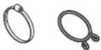
CONNECTING INLET HOSES
CONNECTING INLET HOSES
To produce steam, the dryer must connect to the cold water supply. Since the washer must also connect to the cold water, a "Y" connector is inserted to allow both inlet hoses to make that connection at the same time.
NOTE: Use new inlet hoses; never use old hoses.
- Turn the cold water faucet off. Remove the washer inlet hose from the washer fill valve connector (cold).
- Ensure the rubber flat washer is in place and attach one female coupling of the short hose provided onto the washer fill valve connector. Tighten by hand until firmly seated.
- Attach one male end of the "Y" connector to the other female coupling of the short hose. Ensure the rubber flat washer is in place. Tighten by hand until firmly seated.
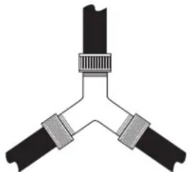
natural_image
Pure diagram of three connected mechanical components without any text, numbers, or symbols- Insert the filter screen in the coupling of the washer's inlet hose. If a rubber flat washer is already in place remove it before installing the filter screen. Attach this coupling to one male end of the "Y" connector. Tighten by hand until firmly seated.
- Ensure the rubber flat washer is in place and attach a 4 ft. to 6 ft. long water inlet hose (may need to be purchased separately) to one male end of the "Y" connector. Tighten by hand until firmly seated.
- Ensure the rubber flat washer is in place and attach the other end of the dryer's long inlet hose to the fill valve connector at the bottom of the dryer back panel. Tighten by hand until firmly seated.
CONNECTING INLET HOSES (cont.)
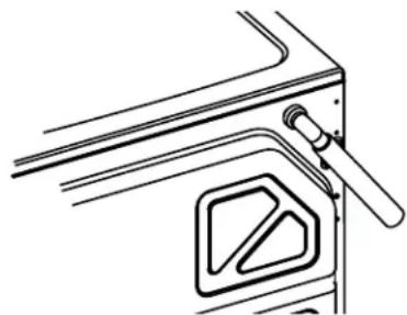
natural_image
Technical line drawing of a mechanical component with no visible text or symbols- Using pliers, tighten all the couplings with an additional two-thirds turn.
NOTE: Do not overtighten. Damage to the couplings may result.
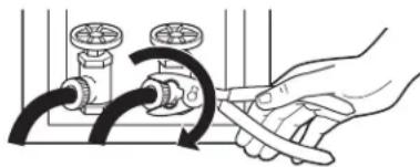
natural_image
Illustration of a hand adjusting a valve with black tubing and a curved arrow indicating rotation (no text or symbols)- Turn the water faucet on.
- Check for leaks around the "Y" connector, faucet and hose couplings.
WATER SUPPLY REQUIREMENTS
Hot and cold water faucets MUST be installed within 42 in. (107 cm) of your washer's water inlet. The faucets MUST be 3/4 in. (1.9 cm) garden hose-type so inlet hoses can be connected. Water pressure MUST be between 10 and 120 pounds per square inch. Your water department can advise you of your water pressure.
NOTE: A water softener is recommended to reduce buildup of scale inside the steam generator if the home water supply is very hard.
CONNECTING A GAS DRYER (skip for electric dryers)
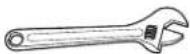
TOOLS YOU WILL NEED
☐ 10" Adjustable wrenches (2)
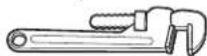
☐ 8" Pipe wrench
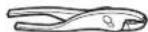
□ Slip-joint pliers
☐ Flat-blade screwdriver
□ Level
MATERIALS YOU WILL NEED
☐ 4" dia. metal elbow
☐ Pipe compound or PTFE tape
☐ Flexible gas line connector
☐ Duct clamps (2) or Spring clamps (2)


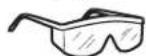
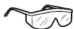
□ Safety glasses
☐ 4" dia. metal duct (recommended)
☐ 4" Cover plate (Kit WE49X22606)

☐ 4" dia., UL-listed flexible metal duct (if needed)
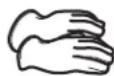
Gloves
□ Soap solution for leak detection

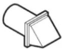
□ Exhaust hood
□ Duct tape
☐ Gas pipe adapters (2), elbow and pipe plug


☐ 4'-6' Water Hose (on some models)
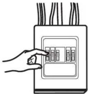
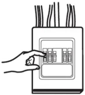
- Before beginning the installation, turn off the circuit breaker(s) or remove the dryer's circuit fuse(s) at the electrical box. Be sure the dryer cord is unplugged from the wall.
natural_image
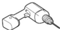
Illustration of a hand inserting a grid into an electrical outlet (no text or symbols)- Turn the dryer's gas shut-off valve in the supply line to the OFF position.
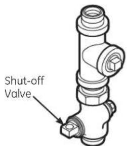
text_image
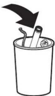
Shut-off Valve- Disconnect and discard old flexible gas connector and ducting material.
natural_image
Simple line drawing of a trash bin with a downward arrow and a cigarette inside (no text or symbols)GAS REQUIREMENTS

WARNING

- Explosion Hazard
- Use a new CSA International approved flexible gas supply line. Never reuse old flexible connectors.
- Install an individual manual shut-off valve within 6ft. of the dryer in accordance with the National Fuel Gas Code, ANSI Z223.1/NFPA 54.
- Securely tighten all gas connections.
- If connected to LP gas, have a qualified person make sure gas pressure DOES NOT exceed 13" water column.
- Examples of a qualified person include: licensed heating personnel, authorized gas company personnel, and authorized service personnel.
- Failure to do so can result in death, explosion, or fire.
- The installation must conform with local codes, or in the absence of local codes, with the National Fuel Gas Code, ANSI Z223.1/NFPA 54, or the Natural Gas and Propane Installation Code, CSA B149.1.
DRYER GAS SUPPLY CONNECTION
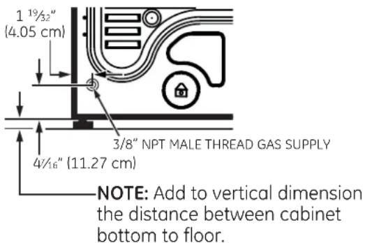
text_image
1 19/32" (4.05 cm) 3/8" NPT MALE THREAD GAS SUPPLY 4/16" (11.27 cm) NOTE: Add to vertical dimension the distance between cabinet bottom to floor.You must use with this dryer a flexible metal connector (listed connector ANSI Z21.24 / CSA 6.10). The length of the connect shall not exceed 3 ft.
GAS SUPPLY
- A 1/8" National Pipe Taper thread plugged tapping, accessible for test gauge connection, must be installed immediately upstream of the gas supply connection to the dryer. Contact your local gas utility should you have questions on the installation of the plugged tapping.
- Supply line is to be 1/2" rigid pipe and equipped with an accessible shutoff within 6 feet of, and in the same room with, the dryer.
- Use pipe thread compound appropriate for natural or LP gas or use PTFE tape.
- Connect flexible metal connector to dryer and gas supply.

WARNING

- Fire Hazard
Dryer as produced by manufacturer is to be used only with a natural gas supply. A manufacturer-supplied conversion kit is required to convert this dryer for propane gas supply. Use propane gas conversion kit WE25M87. Conversion must be made by properly trained and qualified personnel in accordance with local codes and ordinances.
ADJUSTING FOR ELEVATION
- Gas clothes dryers input ratings are based on sea level operation and need not be adjusted for operation at or below 2000 ft. elevation. For operation at elevations above 2000 ft., input ratings should be reduced at a rate of 4 percent for each 1000 ft. above sea level.
- Installation must conform to local codes and ordinances or, in their absence, the NATIONAL FUEL GAS CODE, ANSI Z223.
CONNECTING A GAS DRYER (cont.)
CONNECTING THE DRYER TO THE GAS SUPPLY
A Install a female 3/8" NPT elbow at the end of the dryer gas inlet.
Install a 3/8" flare union adapter to the female elbow.
IMPORTANT: Use a pipe wrench to securely hold on to the end of the dryer gas inlet to prevent twisting the inlet.
NOTE: Apply pipe compound or PTFE tape to the threads of the adapter and dryer gas inlet.
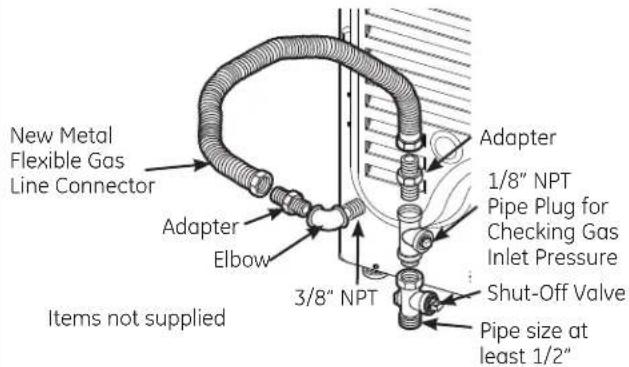
text_image
New Metal Flexible Gas Line Connector Adapter Elbow Items not supplied 3/8" NPT Adapter 1/8" NPT Pipe Plug for Checking Gas Inlet Pressure Shut-Off Valve Pipe size at least 1/2"B Attach the flexible metal gas line connector to the adapter.
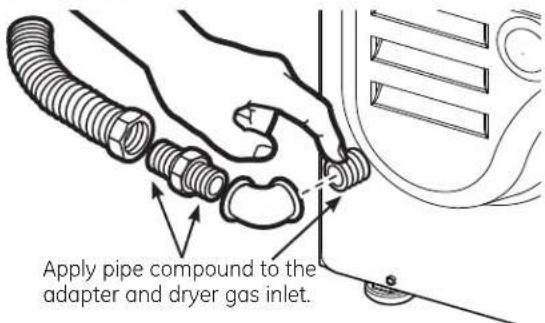
text_image
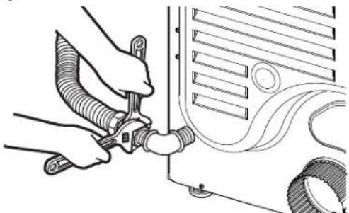
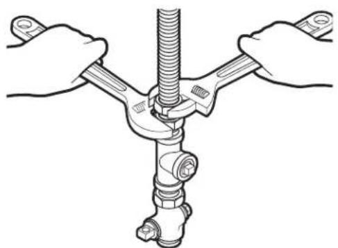
Apply pipe compound to the adapter and dryer gas inlet.C Tighten the flexible gas line connection, using two adjustable wrenches.
natural_image
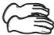
Line drawing of hands connecting hoses to a vehicle hood (no text or symbols)CONNECTING THE DRYER TO THE GAS SUPPLY (cont.)
D Install a 1/8" NPT plugged tapping to the dryer gas line shut-off valve for checking gas inlet pressure.
Install a flare union adapter to the plugged tapping.
NOTE: Apply pipe compound or PTFE tape to the threads of the adapter and plugged tapping.
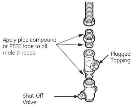
text_image
Apply pipe compound or PTFE tape to all male threads. Plugged Tapping Shut-Off ValveE Tighten all connections, using two adjustable wrenches. Do not overtighten.
natural_image
Illustration of hands connecting a mechanical component to a vertical rod (no text or symbols)F Open the gas shut-off valve.

TEST FOR LEAKS
Never use an open flame to test for gas leaks.
Check all connections for leaks with soapy solution or equivalent.
Apply a soap solution. The leak test solution must not contain ammonia, which could cause damage to the brass fittings.
If leaks are found, close the valve, retighten the joint and repeat the soap test.
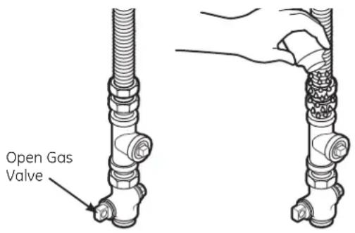
text_image
Open Gas ValveELECTRICAL CONNECTION INFORMATION FOR GAS DRYERS

WARNING

- Electrical Shock Hazard
Plug into a grounded 3 prong outlet.
DO NOT remove ground prong.
DO NOT use an adapter.
DO NOT use an extension cord.
Failure to do so can result in death, fire or electrical shock.
- Circuit – Individual properly polarized and grounded 15 or 20 amp circuit breaker or time-delay fuse.
- Power Supply – 2-wire plus ground, 120 Volt, single phase, 60 Hz, alternating current.
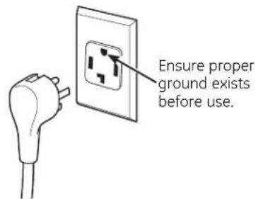
- OutletReceptacle-Properly grounded 3-prong receptacle to be located so the power cord is accessible when the dryer is in an installed position. If a 2-prong receptacle is present, it
is the owner's responsibility to have a licensed electrician replace it with a properly grounded 3-prong grounding type receptacle.
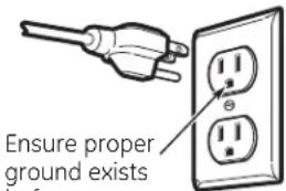
text_image
Ensure proper ground existsEnsure proper ground exists before use.
ELECTRICAL CONNECTION INFORMATION FOR GAS DRYERS (cont.)
- Dryer must be electrically grounded in accordance with local codes and ordinances, or in the absence of local codes, with the latest edition of the NATIONAL ELECTRICAL CODE, ANSI/NFPA NO. 70 or CANADIAN ELECTRICAL CODE, CSA C22.1. Check with a licensed electrician if you are not sure that the dryer is properly grounded.
GROUNDING INSTRUCTIONS
This dryer must be grounded. In the event of a malfunction or breakdown, grounding will reduce the risk of electric shock by providing a path of least resistance for electric current. This dryer uses a cord having an equipment-grounding conductor and a grounding plug. The plug must be plugged into an appropriate outlet that is properly installed and grounded in accordance with all local codes and ordinances.

WARNING
Improper connection of the equipment-grounding conductor
can result in a risk of electric shock. Check with a qualified electrician, or service representative or personnel, if you are in doubt as to whether the appliance is properly grounded. DO NOT modify the plug on the power supply cord. If it will not fit the outlet, have a proper outlet installed by a qualified electrician.
SAVE THESE INSTRUCTIONS
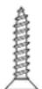
- If required by local codes, an external 18 gauge or larger copper ground wire (not provided) may be added. Attach to dryer cabinet with a #8-18 x ½" sheet metal screw (available at any hardware store) to rear of dryer as illustrated.
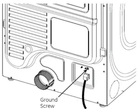
text_image
Ground ScrewCONNECTING AN ELECTRIC DRYER
(Skip for gas dryers and if your dryer already has a power cord attached)
TOOLS YOU WILL NEED
□ Slip-joint pliers
☐ Flat-blade screwdriver
□ Phillips screwdriver
□Level
Before making the electrical connection, turn off the circuit breaker(s) or remove the dryer's circuit fuse(s) at the electrical box. Be sure the dryer cord is unplugged from the wall. NEVER LEAVE THE ACCESS COVER OFF THE TERMINAL BLOCK.
natural_image
Hand placing a button on an electrical outlet panel (no text or symbols visible)MATERIALS YOU WILL NEED
☐ 4" dia. metal elbow
☐ 3/4" Strain relief (UL recognized)
☐ 4" Duct clamps (2) or 4" spring clamps (2)
Safety glasses
☐ 4" dia. metal duct (recommended)
☐ 4" dia., UL-listed flexible metal duct (if needed)
Gloves
Exhaust hood
□ Duct tape
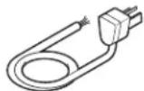
☐ Dryer power cord kit (not provided with dryer)
UL rated 120/240V, 30A with 3 or 4 prongs. Identify the plug type as per the house receptacle before purchasing line cord.
☐4" Cover plate (Kit WE49X22606)

ELECTRICAL CONNECTION INFORMATION FOR ELECTRIC DRYERS For electrical connections using a power cord:

WARNING

- Fire Hazard
Use a new UL-listed 240V 30 amp dryer power supply cord with closed ring terminals or spade terminals with upturned ends.
Use a UL-listed strain relief.
Disconnect power before making electrical connections.
Connect neutral wire (white or center wire) to center terminal.
Ground wire (green or bare wire) must be connected to green ground connector.
Connect remaining two supply wires to remaining two terminals.
Securely tighten all electrical connections.
Replace the terminal block cover.
Failure to do so can result in death, fire or electrical shock.
GROUNDING INSTRUCTIONS
For a grounded, cord-connected dryer: This dryer must be grounded. In the event of a malfunction or breakdown, grounding will reduce the risk of electric shock by providing a path of least resistance for electric current. This dryer uses a cord having an equipment-grounding conductor and a grounding plug. The plug must be plugged into an appropriate outlet that is properly installed and grounded in accordance with all local codes and ordinances.

WARNING
Improper connection of the equipment-grounding conductor
can result in a risk of electric shock. Check with a qualified electrician, or service representative or personnel, if you are in doubt as to whether the appliance is properly grounded. DO NOT modify the plug on the power supply cord. If it will not fit the outlet, have a proper outlet installed by a qualified electrician.
SAVE THESE INSTRUCTIONS
ELECTRICAL CONNECTION INFORMATION FOR ELECTRIC DRYERS For direct wire connections:

WARNING

- Fire Hazard
Use 10 gauge copper wire.
Use a UL-listed strain relief.
Disconnect power before making electrical connections.
Connect neutral wire (white or center wire) to center terminal.
Ground wire (green or bare wire) must be connected to green ground connector.
Connect remaining two supply wires to remaining two terminals.
Securely tighten all electrical connections.
Replace the terminal block cover.
Failure to do so can result in death, fire or electrical shock.
GROUNDING INSTRUCTIONS
For a permanently connected dryer: This dryer must be connected to a grounded metal, permanent wiring system, or an equipment-grounding conductor must be run with the circuit conductors and connected to the equipment-grounding terminal on the appliance.

WARNING
Improper connection of the equipment-grounding conductor
can result in a risk of electric shock. Check with a qualified electrician, or service representative or personnel, if you are in doubt as to whether the appliance is properly grounded.
SAVE THESE INSTRUCTIONS
CONNECTING AN ELECTRIC DRYER (cont.)
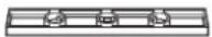
CONNECTING DRYER USING 4-WIRE CONNECTION (MUST BE USED FOR MOBILE HOME INSTALLATION)
NOTE: Since January 1, 1996, the National Electrical Code requires that new constructions use a 4-wire connection to an electric dryer. A 4-wire cord must also be used where local codes do not permit grounding through the neutral.
3-wire connection is NOT for use on new construction.
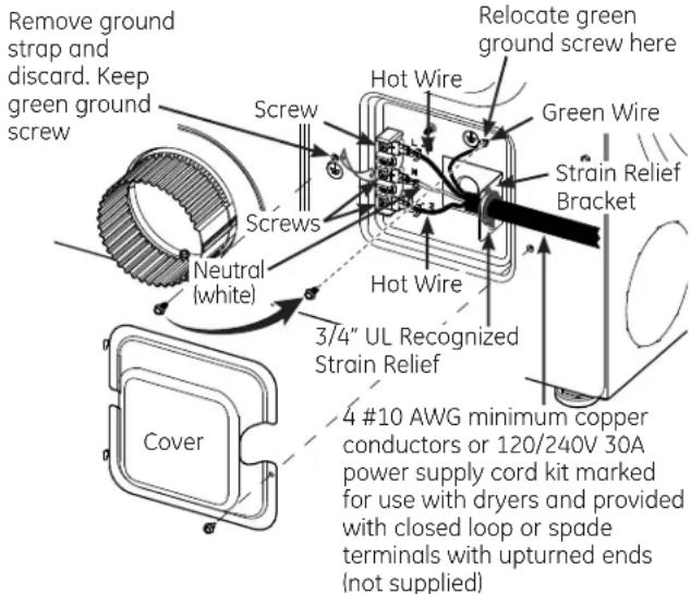
text_image
Remove ground strap and discard. Keep green ground screw Screw Neutral (white) Cover Hot Wire Relocate green ground screw here Green Wire Strain Relief Bracket Hot Wire 3/4" UL Recognized Strain Relief 4 #10 AWG minimum copper conductors or 120/240V 30A power supply cord kit marked for use with dryers and provided with closed loop or spade terminals with upturned ends (not supplied)- Turn off the circuit breaker(s) (30 amp) or remove the dryer's circuit fuse at the electrical box.
- Be sure the dryer cord is unplugged from the wall receptacle.
- Remove the power cord cover located at the lower back.
- Remove and discard ground strap. Keep the green ground screw for Step 7.
- Install 3/4 in. UL-recognized strain relief to power cord entry hole. Bring power cord through strain relief.
- Connect power cord as follows:
A. Connect the 2 hot lines to the outer screws of the terminal block (marked L1 and L2).
B. Connect the neutral (white) line to the center of the terminal block (marked N). - Attach ground wire of power cord with the green ground screw (hole above strain relief bracket). Tighten all terminal block screws (3) securely.
- Properly secure power cord to strain relief.
- Reinstall the cover.
text_image
If required, by local code, install external ground (not provided) to grounded metal, cold water pipe, or other established ground determined by a qualified electrician. Green Ground Screw Ground Strap Screw Hot Wire Strain" Relief Bracket Screws Neutral (white) Hot Wire 3/4" UL Recognized Strain Relief Cover 3 #10 AWG minimum copper conductors or 120/240V 30A power supply cord kit marked for use with dryers and provided with closed loop or spade terminals with upturned ends (not supplied)3-wire Connection
Not for use in Canada.
DO NOT use for Mobile Home Installations.
NOT for use on new construction.
NOT for use on recreational vehicles.
NOT for use in areas where local codes prohibit grounding through the neutral conduction.
- Turn off the circuit breaker(s) (30 amp) or remove the dryer's circuit fuse at the electrical box.
- Be sure the dryer cord is unplugged from the wall receptacle.
- Remove the power cord cover located at the lower back.
-
Install 3/4-in. UL-recognized strain relief to power cord entry hole. Bring power cord through strain relief.
-
Connect power cord as follows:
A. Connect the 2 hot lines to the outer screws of the terminal block (marked L1 and L2).
B. Connect the neutral (white) line to the center of the terminal block (marked N).
-
Be sure ground strap is connected to neutral (center) terminal of block and to green ground screw on cabinet rear. Tighten all terminal block screws (3) securely.
-
Properly secure power cord to strain relief.
-
Reinstall the cover.
This dryer MUST be vented to the outdoors.
Use only 4" rigid metal ducting for the home exhaust duct.
Use only 4" rigid metal or UL-listed dryer transition duct to connect the dryer to the home exhaust.
DO NOT use a plastic vent.
DO NOT exhaust into a chimney, kitchen exhaust, gas vent, wall, ceiling, attic, crawl space, or concealed space of a building.
DO NOT install a screen in or over the exhaust duct.
DO NOT install a booster fan in the exhaust duct.
DO NOT use duct longer than specified in the exhaust length table.
Failure to follow these instructions can result in death or fire.
PARTS AVAILABLE FROM GEAPPLIANCES.COM OR LOCAL SERVICE ORGANIZATIONS
PM8X85
Outdoor exhaust hood
PM08X10085
8' Flexible metal clothes dryer transition duct with 2 clamps
WX08X10130
4" Dryer exhaust clamp
WE49X22606
Rear exhaust opening cover, for side or bottom vented dryers
EXHAUST SYSTEM CHECKLIST
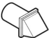
HOOD OR WALL CAP
- Terminate in a manner to prevent back drafts or entry of birds or other wildlife.
- Termination should present minimal resistance to the exhaust airflow and should require little or no maintenance to prevent clogging.
- Wall caps must be installed at least 12" above ground level or any other obstruction with the opening pointed down.
- Never vent the dryer out of the roof.
SEPARATION OF TURNS
- For best performance, separate all turns by at least 4 ft. of straight duct, including distance between last turn and dampened wall cap.
SEALING OF JOINTS
- All joints should be tight to avoid leaks. The male end of each section of duct must point away from the dryer.
- Duct joints should be made air- and moisture-tight by wrapping the overlapped joints with duct tape or aluminum tape.
- Do not assemble ductwork with any fasteners that extend into the duct. These fasteners can accumulate lint, creating a potential fire hazard.
- Horizontal runs should slope down towards the outdoors 1/4" per foot.
- Provide an access for inspection and cleaning of the exhaust system, especially at turns and joints. Exhaust system shall be inspected and cleaned at least once a year.
INSULATION
- Ductwork that runs through an unheated area or is near air conditioning should be insulated to reduce condensation and lint buildup.
TOOLS AND MATERIALS YOU WILL NEED TO INSTALL EXHAUST DUCT
☐ Phillips-head screwdriver
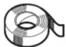
☐ Duct tape or duct clamp
☐ Rigid or UL-listed flexible metal 4" (10.2 cm) duct
☐ Drill with 1/8" drill bit (for bottom venting)
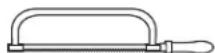
□ Hacksaw
□ Vent hood
EXHAUSTING THE DRYER (cont.)
CONNECTING THE DRYER TO HOUSE VENT
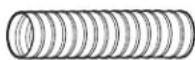
RIGID METAL TRANSITION DUCT
- For best drying performance, a rigid metal transition duct is recommended.
- Rigid metal transition ducts reduce the risk of crushing and kinking.
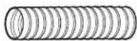
UL-LISTED FLEXIBLE METAL (SEMI-RIGID) TRANSITION DUCT
- If rigid metal duct cannot be used, then UL-listed flexible metal (semi-rigid) ducting can be used (Kit PM08X10085).
- Never install flexible metal duct in walls, ceilings, floors or other enclosed spaces.
- Total length of flexible metal duct should not exceed 7' 9" (2.4 m).
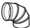
- For many applications, installing elbows at both the dryer and the wall is highly recommended (see illustrations at right). Elbows allow the dryer to sit close to the wall without kinking and/or crushing the transition duct, maximizing drying performance.
- Avoid resting the duct on sharp objects.
UL-LISTED FLEXIBLE METAL (FOIL-TYPE) TRANSITION DUCT
- In special installations, it may be necessary to connect the dryer to the house vent using a flexible metal (foil-type) duct. A UL-listed flexible metal (foil-type) duct may be used ONLY in installations where rigid metal or flexible metal (semi-rigid) ducting cannot be used AND where a 4" diameter can be maintained throughout the entire length of the transition duct.
- In Canada and the United States, only the flexible metal (foil-type) ducts that comply with the "Outline for Clothes Dryer Transition Duct Subject 2158A" shall be used.
- Never install flexible metal duct in walls, ceilings, floors or other enclosed spaces.
- Total length of flexible metal duct should not exceed 7' 9" (2.4 m).
- Avoid resting the duct on sharp objects.
- For best drying performance:
-
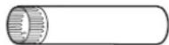
Slide one end of the duct over the clothes dryer outlet pipe.
-
Secure the duct with a clamp.
-
With the dryer in its permanent position, extend the duct to its full length. Allow 2" of duct to overlap the exhaust pipe. Cut off and remove excess duct. Keep the duct as straight as possible for maximum airflow.
-
Secure the duct to the exhaust pipe with the other clamp.
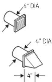
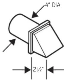
FOR TRANSITION VENTING (DRYER TO WALL), DO:
natural_image
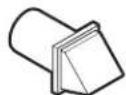
Technical line drawing of a mechanical device with no visible text or symbols- DO cut duct as short as possible and install straight into wall.
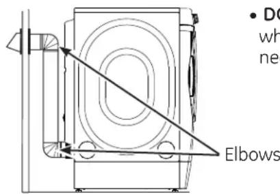
text_image
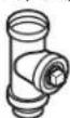
• DC wh nee Elbows• DO use elbows when turns are necessary.
DO NOT:
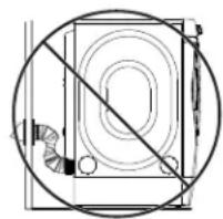
natural_image
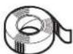
Pure technical diagram of a mechanical component with no text or symbols, showing a circular outline and diagonal line (no text or symbols)- DO NOT bend or collapse ducting. Use elbows if turns are necessary.
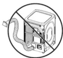
natural_image
Diagram of a computer with a CPU socket and cord, enclosed in a circle (no text or symbols)• DO NOT use excessive exhaust length. Cut duct as short as possible.
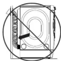
natural_image
Pure mechanical diagram showing a circular component with internal components and a diagonal line, no text or symbols present.• DO NOT crush duct against the wall.
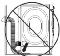
• DO NOT set dryer on duct.
EXHAUST LENGTH
Using exhaust longer than specified length will:
- Increase the drying times and the energy cost.
- Reduce the dryer life.
- Accumulate lint, creating a potential fire hazard.
The correct exhaust installation is YOUR RESPONSIBILITY.
Problems due to incorrect installation are not covered by the warranty.
The MAXIMUM ALLOWABLE length of the exhaust system depends upon the type of duct, number of turns, the type of exhaust hood (wall cap) and all conditions noted on the chart.
- Internal elbows added for side or bottom vent conversions must be included in the total elbow count.
- Any elbow greater than 45^ should be treated as a 90^ elbow.
- Two 45^ elbows will be treated like one 90^ elbow.
- For the side exhaust installations, add one 90° elbow to the chart.
- When calculating the total vent system length, you must add all the straight portions and elbows of the system (including the transition duct).
EXHAUST LENGTH
| RECOMMENDED MAXIMUM LENGTH | |
| Exhaust Hood Types | |
| Recommended Use only for short- run installations | |
 |  |
| Rigid Rigid Metal Metal | |
| 60 Feet45 Feet35 Feet25 Feet15 Feet | |
EXHAUSTING THE DRYER (cont.)
BEFORE YOU BEGIN
- Remove and discard existing plastic or metal foil duct and replace with UL-listed duct.
- Remove any lint from the wall exhaust opening.
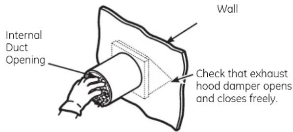
text_image
Internal Duct Opening Wall Check that exhaust hood damper opens and closes freely.STANDARD REAR EXHAUST
We recommend that you install your dryer before installing your washer. This will permit direct access for easier exhaust connection.
Slide the end of the exhaust duct on the back of the dryer and secure with duct tape or a hose clamp.
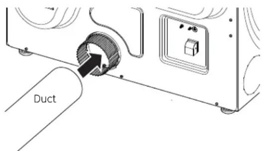
text_image
DuctNOTE: We strongly recommend using rigid metal exhaust duct. However, if flexible ducting is used it must be UL-Listed metal, not plastic.
- For straight-line installation, connect the dryer exhaust to the wall, using duct tape.
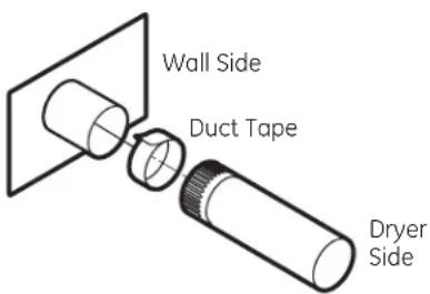
text_image
Wall Side Duct Tape Dryer SideRECOMMENDED CONFIGURATION TO MINIMIZE EXHAUST BLOCKAGE
Using duct elbows will prevent duct kinking and collapsing.
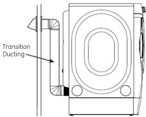
text_image
Transition DuctingSIDE VENTING:
Dryer Exhaust to right of cabinet for Electric models only.
Dryer Exhaust to left of cabinet for Gas and Electric models.
WARNING

- Fire Hazard
Disconnect dryer from electrical supply.
Wear gloves and arm guards.
Close the back opening with cover plate (Kit WE49X22606).
Failure to do so may result in fire, electrical shock or lacerations.
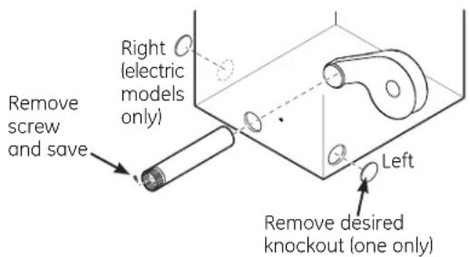
text_image
Right (electric models only) Remove screw and save Left Remove desired knockout (one only)Detach and remove the right (electric models only) or left side knockout as desired. Remove the screw inside the dryer exhaust duct and save. Pull the duct out of the dryer.
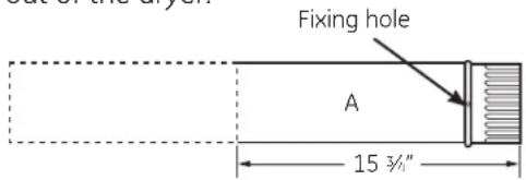
text_image
Fixing hole A 15 3/4"Cut the duct as shown and keep portion A.
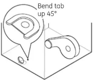
TAB LOCATION
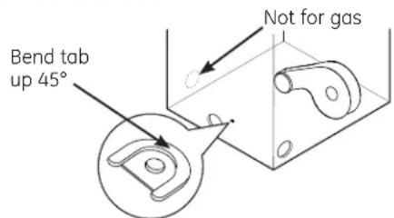
text_image
Bend tab up 45° Not for gasThrough the rear opening, locate the tab in the middle of the appliance base. Lift the tab to about 45^ , using a flat-blade screwdriver.
ADDING A NEW DUCT
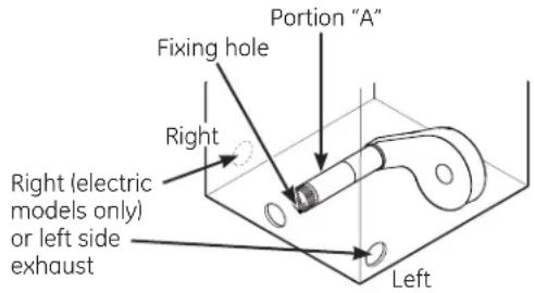
text_image
Fixing hole Right Right (electric models only) or left side exhaust Left Portion "A"Reconnect the cut portion (A) of the duct to the blower housing. Make sure that the shortened duct is aligned with the tab in the base. Use the screw saved previously to secure the duct in place through the tab on the appliance base.
ADDING ELBOW AND DUCT FOR EXHAUST TO SIDE OF CABINET
- Insert the 4" elbow through the rear opening and connect the elbow to the dryer internal duct.
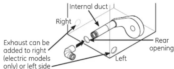
text_image
Internal duct Right Exhaust can be added to right (electric models only) or left side Left Rear opening- Insert the 4" duct through the side opening and connect it to the elbow.
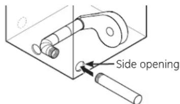
text_image
Side openingDo not pull or damage the electrical wires and do not remove the vinyl cover from the electrical components inside the dryer when inserting the duct. A slight interference may occur between the exhaust and the wire components.
EXHAUSTING THE DRYER (cont.)
SIDE VENTING (cont.)
ADDING ELBOW AND DUCT FOR EXHAUST TO LEFT OR RIGHT SIDE OF CABINET (cont.)
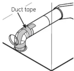
- Apply duct tape as shown on the joint between the dryer internal duct and the elbow, and also the joint between the elbow and the side duct.
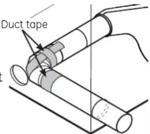
text_image
Duct tapeUse 4" rigid metal ducting only inside the dryer. Internal duct joints must be secured with tape, otherwise they may separate and cause a safety hazard.
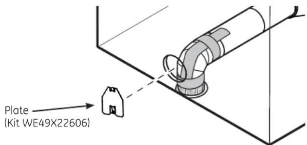
ADDING COVER PLATE TO REAR OF CABINET (SIDE EXHAUST)
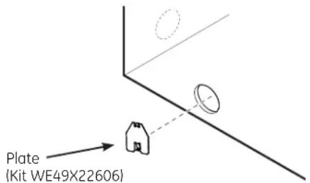
text_image
Plate (Kit WE49X22606)Connect standard metal elbows and ducts to complete the exhaust system. Cover back opening with a plate (Kit WE49X22606) available from your local service provider. Place dryer in final location.
NEVER LEAVE THE BACK OPENING WITHOUT THE PLATE. (Kit WE49X22606.)
BOTTOM VENTING:
Dryer Exhaust to the bottom of cabinet for Gas and Electric models WITHOUT Built-In Pedestal™.

WARNING

- Fire Hazard
Close the back opening with cover plate (Kit WE49X22606).
Disconnect dryer from electrical supply.
Wear gloves and arm guards.
Failure to do so may result in fire, electrical shock or lacerations.
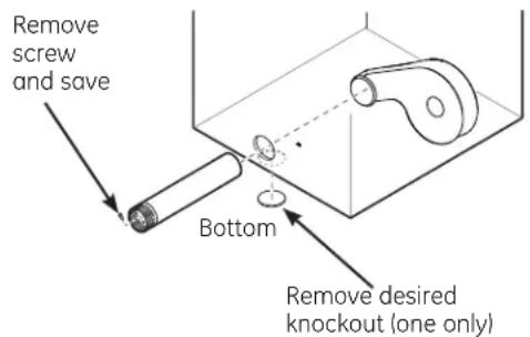
text_image
Remove screw and save Bottom Remove desired knockout (one only)Remove the screw inside the dryer exhaust duct and save. Pull the duct out of the dryer. Detach and remove the bottom knockout.
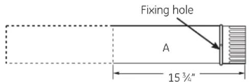
text_image
Fixing hole A 15 3/4"Cut the duct as shown and keep portion A.
BOTTOM VENTING (cont.)
ADDING A NEW DUCT
- Through the rear opening, locate the tab in the middle of the appliance base. Lift the tab to about 45° using a flat-blade screwdriver.
- Reconnect the cut portion (A) of the duct to the blower housing. Make sure that the shortened duct is aligned with the tab in the base.
Use the screw saved previously to secure the duct in place through the tab on the appliance base.
- Insert the 4" elbow through the bottom opening and connect to the dryer internal duct.
text_image
Bend tab up 45°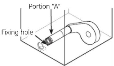
text_image
Portion "A" Fixing hole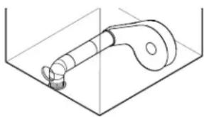
natural_image
Technical line drawing of a mechanical component inside a transparent container (no text or symbols)Be sure not to pull or damage the electrical wires inside the dryer when inserting the duct.
- Apply duct tape as shown on the joint between the dryer internal duct and the elbow, and also the joint between the elbow and the bottom duct.
text_image
Duct tapeInternal duct joints must be secured with tape; otherwise, they may separate and cause a safety hazard.
ADDING COVER PLATE TO REAR OF CABINET (BOTTOM EXHAUST)
text_image
Plate (Kit WE49X22606)Connect standard metal elbows and ducts to complete the exhaust system. Cover back opening with a plate (Kit WE49X22606) available from your local service provider. Place dryer in final location.
NEVER LEAVE THE BACK OPENING WITHOUT THE PLATE. (Kit WE49X22606.)
FINAL SETUP
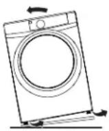
① LEVEL THE DRYER
Stand the dryer upright near the final location and adjust the four leveling legs at the corners to ensure that the dryer is level from side to side and front to rear.
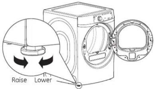
text_image
Raise Lower③ DRYER START-UP
Press the Power button.
NOTE: If the dryer has been exposed to temperatures below freezing for an extended period of time, allow it to warm up before pressing Power. Otherwise, the display will not come on. The dryer is now ready for use.
② PLUG DRYER IN
text_image
Ensure proper ground exists before use.REVERSING THE DOOR SWING (if desired)
IMPORTANT NOTES
- Read the instructions all the way through before starting.
- Handle parts carefully to avoid scratching paint.
- Set screws down by their related parts to avoid using them in the wrong places.
- Provide a non-scratching work surface for the doors.
- Normal completion time to reverse the door swing is 30–60 minutes.
IMPORTANT: Once you begin, do not move the cabinet until door-swing reversal is completed.
These instructions are for changing the hinges from the right side to the left side—if you ever want to switch them back to the right side, follow these same instructions and reverse all references to the left and right.
TOOLS YOU WILL NEED
☐ #2 Phillips-head screwdriver
□ T-25 torx driver
☐ 1/4" nut driver
DOOR PARTS
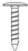
10 - #8 × 7/8" Screws (door assembly)

2 - #8 × 1/2" Screws (striker plate)

6 - #8 x 1/2" Screws (hinge assembly and handle spacer)

2 - #8 × 1/2" Screws (door mask)
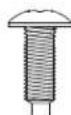
2 - #10 × 5/8" Screws (hinge)
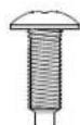
2 - #10 × 5/8" Screws (panel plug)

1 - #8 × 3/8" Screws (hinge pin)
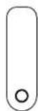
2 - Panel Plugs (on some models)
1 - Door Striker (on some models)
1 - Door Mask 1 - Chrome Door Cover Assembly
1 - Handle Spacer (on some models)

1 - Handle
Spacer/Latch
Assembly
(on some models)
1 - Inner Door Assembly

1 - Door Plug (on some models)
BEFORE YOU START
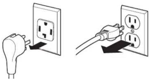
Unplug the dryer from its electrical outlet.
natural_image
Two-step diagram showing a hand inserting an electrical outlet into a socket, with no text or symbols present.REVERSING THE DOOR SWING (if desired)
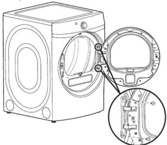
① REMOVE THE DOOR ASSEMBLY
A. Open the door fully. B. Remove 2 screws (#10 × 5/8") from the hinge, starting with the bottom screw. The door will tilt away from the front panel, but will come to rest in place.
text_image
Technical diagram of a washing machine with labeled components and close-up views showing internal structure details.C. Lift the door slightly and unhook if from the front panel. D. Place the door on a soft and flat surface.
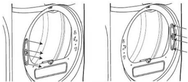
2A RE-LOCATE THE HINGE STRIKER AND FRONT PANEL PLUGS (on some models - see step 2B below for other models)
IMPORTANT: Note the location of the hinge (left or right) before removing.
A. Remove 2 screws (#10 x 5/8") and front panel plugs from the front panel. B. Re-install front panel plugs and screws on opposite side of the door opening. C. Remove 2 screws (#8 x 1/2") and hinge striker from the front panel. D. Rotate hinge striker 180 degrees and re-install with screws on the opposite side of the door opening.
text_image
Technical diagram showing two views of a mechanical component with labeled parts and directional arrows indicating motion or force.2B RE-LOCATE THE HINGE STRIKER (on some models - see step 2A above for other models)
IMPORTANT: Note the location of the hinge (left or right) before removing.
A. Remove 2 screws (#10 x 5/8") from top and bottom of door striker. B. Remove 2 screws (#8 x 1/2") from center of door striker and remove door striker from front panel. C. Rotate door striker 180 degrees and re-install with screws on the opposite side of the door opening.
text_image
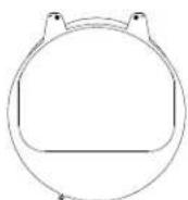
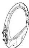
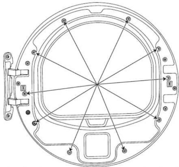
Technical diagram showing two views of a mechanical component with labeled dimensions and directional arrows③ DISASSEMBLE THE DOOR ASSEMBLY
A. Place door on a soft and flat surface with the inner door frame facing upward.
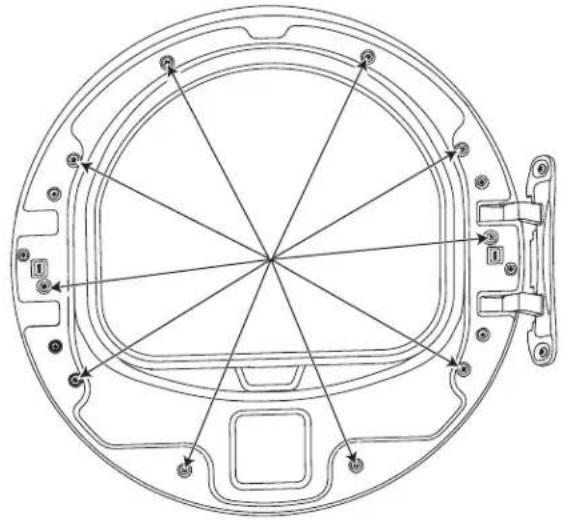
B. Remove 10 screws ( 8 × 7/8" ) from the perimeter of the door frame.
C. Separate the inner door frame from the chrome door cover. Set the inner door frame aside on a soft and flat surface.
natural_image
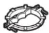
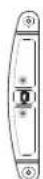
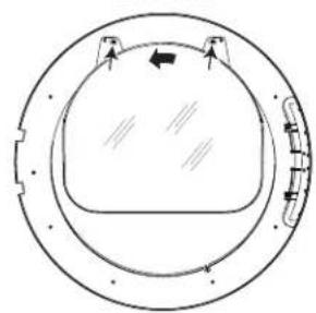
Technical line drawing of a circular mechanical component with radial and concentric lines, no text or symbols present4 RE-LOCATE THE DOOR MASK
A. Place the chrome door cover on a soft and flat surface so that the door mask is facing upwards.
B. Remove 2 screws ( 8 × 1/2" ) that secure the door mask in place.
C. Rotate the door mask 180 degrees and re-install screws to secure door mask.
BEFORE
natural_image
Diagram of a circular mechanical component with internal features and directional arrows (no text or symbols)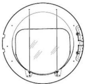
natural_image
Simple line drawing of a circular mechanical component with internal channels and mounting holes (no text or symbols)AFTER
D. Re-location is complete. Set chrome door cover aside.
REVERSING THE DOOR SWING (if desired)
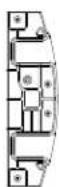
5 RE-LOCATE HINGE ASSEMBLY AND HANDLE SPACER
A. Place the inner door frame on a soft and flat surface so that the inner door gasket is facing upwards.
B. Remove 6 screws ( 8 × 1/2" ) that secure the hinge assembly and handle spacer.
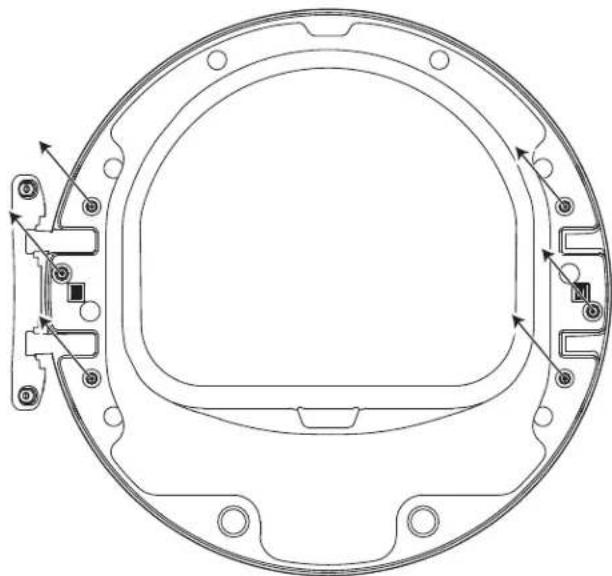
natural_image
Technical line drawing of a circular mechanical component with mounting holes and internal features (no text or symbols)C. Separate the hinge assembly, door plug (on some models), handle spacer or handle spacer/latch assembly (depending on model) from the inner door frame.
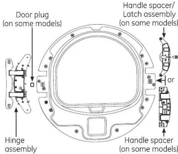
text_image
Door plug (on some models) Handle spacer/ Latch assembly (on some models) or Handle spacer (on some models) Hinge assembly⑤ RE-LOCATE HINGE ASSEMBLY AND HANDLE SPACER (cont.)
D. Rotate hinge assembly 180 degrees and re-locate it and the door plug (on some models) on the opposite side of the inner door frame.
E. Rotate the handle spacer or handle spacer/latch assembly (depending on model) 180 degrees and re-locate on the opposite side of the inner door frame.
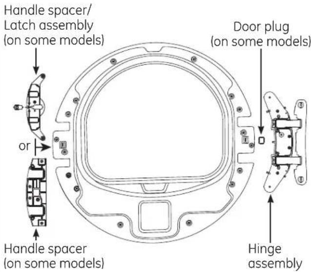
text_image
Handle spacer/ Latch assembly (on some models) or Handle spacer (on some models) Door plug (on some models) Hinge assemblyF. Re-install screws securing hinge assembly and handle spacer.
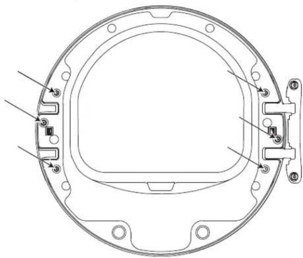
natural_image
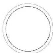
Technical line drawing of a circular mechanical component with mounting holes and internal features (no text or symbols)6 RE-ASSEMBLE DOOR ASSEMBLY
A. Place the chrome door cover on a soft flat surface with the plastic outer protect cover facing down.
B. Lower the inner door frame onto the chrome door cover.
C. Ensure that all screw holes are aligned and re-install 10 screws ( 8 × 7/8" ).
natural_image
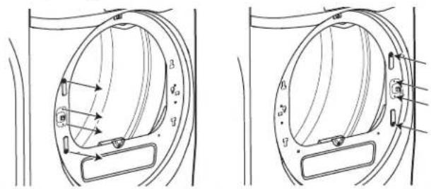
Technical line drawing of a circular mechanical component with internal structural lines and mounting points (no text or symbols)7 RE-LOCATE HINGE PIN SCREW
A. Remove the hinge pin screw from the hole labeled "D".
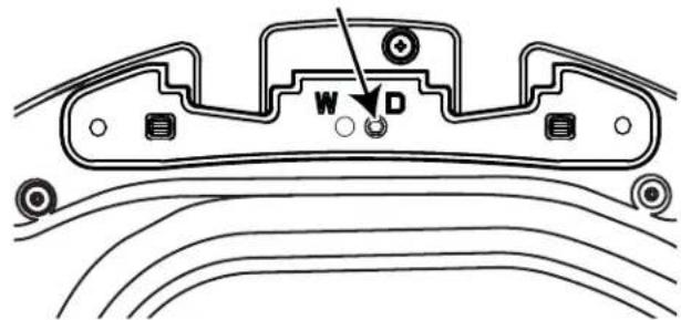
text_image
W DB. Re-install the hinge pin screw into the hole labeled "W".
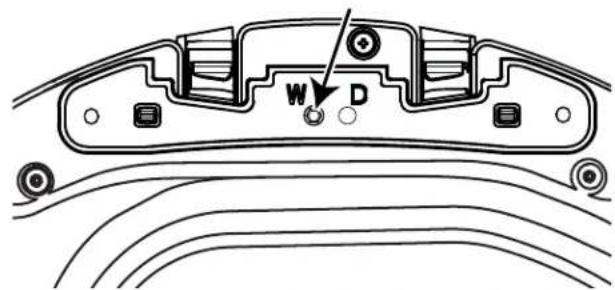
text_image
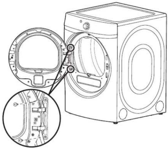
W D8 RE-INSTALL DOOR ASSEMBLY
A. Install the door assembly by guiding the hinge pin screw head through the key hole on the front panel and lowering the door assembly into place.
B. Open the door approximately 140 degrees to provide access to the screw hole locations.
C. Starting with the top screw, re-install the 2 screws (#10 × 5/8") which secure the door to the front panel.
natural_image
Line drawing of a washing machine with internal components and close-up insets (no text or symbols)STACKING THE WASHER AND DRYER (if desired)
BEFORE YOU BEGIN
Read these instructions completely and carefully.
- IMPORTANT – Save these instructions for local electrical inspector's use.
- IMPORTANT – Observe all governing codes and ordinances.
- Note to Installer – Be sure to leave these instructions with the Consumer.
- Note to Consumer – Keep these instructions for future reference.
- Service must be performed by a qualified installer.
- Proper installation is the responsibility of the installer.
- Disconnect power before installing. Failure to do so could result in serious injury or death.
WARNING

Excessive Weight Hazard
Use two or more people to install dryer. Failure to do so may result in back or other injury.
- Avoid Tipping and Rupture of Utility Services. Dryer must be securely attached to the washer. DO NOT place the washer on top of the dryer. Failure to do so could result in personal injury/death or property damage.
- Mobile Home or Manufactured Home Installation – Stacking of a gas dryer is not permitted in a mobile home or manufactured home.
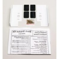
GE APPLIANCES STACK KIT:
Order on-line at GEApplianceParts.com, 24 hours a day or by phone at 877.959.8688 during normal business hours.
Part Number Accessory
GEFLSTACK Complete Stack Kit
MINIMUM CLEARANCE OTHER THAN ALCOVE OR CLOSET INSTALLATION
Minimum clearance to combustible surfaces and for air opening are: 0" both sides, 1" rear and 1" top. Consideration must be given to provide adequate clearance for installation and service.
REQUIREMENTS FOR ALCOVE OR CLOSET INSTALLATION
WARNING

- Explosion Hazard
Keep flammable materials and vapors, such as gasoline, away from dryer.
Place dryer at least 18" (46 cm) above the floor for a garage installation.
Failure to do so can result in death, explosion, or fire.
- The dryer MUST be vented to the outdoors.
- Minimum clearance between dryer cabinet and adjacent walls or other surfaces is:
0" either side
1" front and rear
1" top - Consideration must be given to provide adequate clearance for installation and service.
- Closet doors must be louvered or otherwise ventilated and have at least 60 square inches of open area. If the closet contains both a washer and a dryer, doors must contain a minimum of 120 square inches of open area.
NOTE: WHEN THE EXHAUST DUCT IS LOCATED AT THE REAR OF THE DRYER, THE CONFIGURATION OF THE DUCTING MAY REQUIRE GREATER THAN 3" OF REAR CLEARANCE.
Gas Dryers Only:
- No other fuel burning appliance shall be installed in the same closet as a gas dryer.
- The dryer must be disconnected from the gas supply piping during pressure testing at pressures greater than 12 psi (3.5 kPa).
- A 1/8 inch NPT minimum plugged tapping, accessible for test gauge connection, must be installed immediately upstream of the gas supply connection to the dryer.
STACKING THE WASHER AND DRYER (if desired) (cont.)
STACKING KIT GEFLSTACK CONTENTS (OPTIONAL ACCESSORY)
NOTE: Models with Built-In Pedestal™ cannot be stacked.
☐ Left hand bracket
☐ 4 #12 × 1" screws
☐ Right hand bracket

☐ 4 #8 × 1/2" screws
□ 4 rubber pads
TOOLS YOU WILL NEED
□ Phillips screwdriver
Gloves
□ Open-ended wrench

□ Level
□ Pliers
INSTALLATION PREPARATION
Remove the packaging.
Flatten the product carton to use as a pad to lay the dryer down on its side. Continue using the carton to protect the finished floor in front of the installation location.
INSTALLING THE STACK BRACKET KIT
1 REMOVE THE DRYER LEVELING LEGS
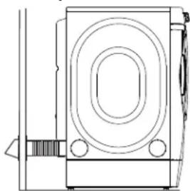
A. Carefully lay the dryer on its side. Use the packing material so you don't scratch the finish on the dryer.
natural_image
Line drawing of a washing machine with circular vent and side door (no text or symbols)B. Use an open-end wrench or pliers to remove the dryer leveling legs.
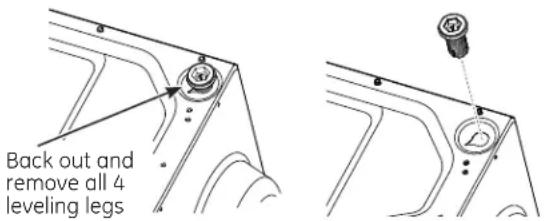
text_image
Back out and remove all 4 leveling legs② INSTALL RUBBER PADS TO DRYER BASE
Locate the 4 rubber pads in the parts package. Remove the adhesive backing and firmly place over each bracket where you removed the leveling legs.
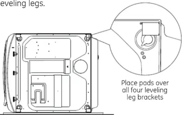
text_image
Leveling legs. Place pads over all four leveling leg brackets3 INSTALL BRACKET TO DRYER
A. Align the holes in the left bracket with the holes in the bottom left corner of the dryer. Use a Phillips screwdriver to install the 2 #12 x 1" tapping screws.
B. Repeat the above step with the right bracket on the bottom right corner of the dryer.
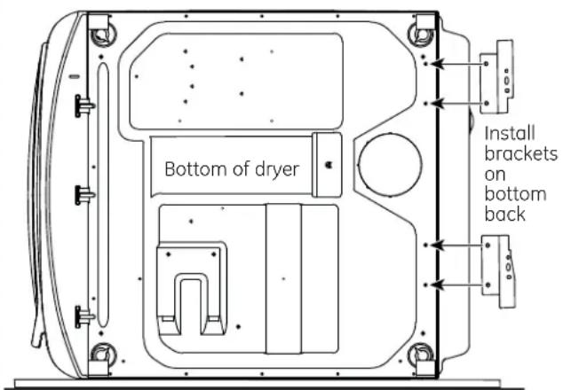
text_image
Bottom of dryer Install brackets on bottom backC. Set the dryer upright.
NOTE: Make sure to set the dryer on a piece of packing material so the brackets that are attached to the bottom of the dryer do not damage the floor.
4 INSTALL DRYER AND BRACKET ON WASHER
A. Lift the dryer on top of the washer. Be careful not to scratch the top of the washer with the brackets. Protect the washer control panel with cardboard or other protection. Be sure to lift the dryer high enough to clear the washer control panel.
More than two people are recommended to lift the dryer into position because of its weight and size. Failure to do so could result in personal injury or death.
4 INSTALL DRYER AND BRACKET ON WASHER (cont.)
B. Align the holes in the bracket with the holes in the back of the washer. Using a Phillips screwdriver, attach the 2 #8 x 1/2" tapping screws. Repeat on both sides of the washer.
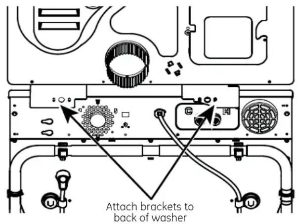
text_image
Attach brackets to back of washer5 FINALIZE THE INSTALLATION
A. Refer to the washer Installation Instructions to complete the washer installation.
B. Refer to the dryer Installation Instructions to complete the dryer installation.
C. Carefully slide or walk the stacked washer and dryer into place. Use felt pads or other sliding device to assist moving and to protect flooring.
Do not push on the dryer once installed to top of the washer. Pushing on the dryer may result in pinched fingers.
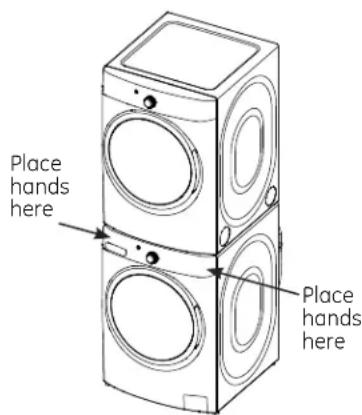
text_image
Place hands here Place hands hereTroubleshooting Tips
Save time and money! Review the charts on the following pages, or visit GEAppliances.com. You may not need to call for service.
| Problem Possible Causes What To Do | ||
| Dryer shakes or makes noise | Some shaking/noise is normal. Dryer may be sitting unevenly. | Move dryer to an even floor space, or adjust leveling legs as necessary until even. |
| Clothes take too long to dry | Improper or obstructed ducting | Check the Installation Instructions to make sure the dryer venting is correct.Make sure ducting is clean, free of kinks and unobstructed.Check to see if outside wall damper operates easily. |
| Improper sorting Separate heavy items from lightweight items (generally, a well-sorted washer load is a well-sorted dryer load). | ||
| Large loads of heavy fabrics (like beach towels) | Large, heavy fabrics contain more moisture and take longer to dry.Separate large, heavy fabrics into smaller loads to speed drying time. | |
| Controls improperly set Match control settings to the load you are drying. | ||
| Lint filter is full Clean lint filter before every load. | ||
| Blown fuses or tripped circuit breaker | Replace fuses or reset circuit breakers. Since most dryers use 2 fuses/breakers, make sure both are operating. | |
| Overloading/combining loads | Do not put more than one washer load in the dryer at a time. | |
| Underloading If you are drying only one or two items, add a few items to ensure proper tumbling. | ||
| eDry is enabled The eDry feature is designed to operate your dryer in the most energy efficient mode, which is not always the fastest mode. In some instances, dry times may be extended to reduce overall energy usage for the cycle. | ||
| The Dry dryness level was chosen but load is still damp | Load consists of a mixture of heavy and light fabrics | When combining heavy and light fabrics in a load, choose More Dry. |
| Exhaust system is blocked Inspect and clean exhaust system. | ||
| Control buttons not responding | Controls accidentally put in service mode | Press Start/Pause. |
| Controls accidentally put in lock mode | Hold the Lock Control button for 3 seconds to unlock the dryer. | |
| Controls performed an incorrect operation | Reset the in-house breaker. | |
| Dryer doesn't start | Control panel is "asleep" | This is normal. Press Power to activate the control panel. |
| Dryer is unplugged Make sure the dryer plug is pushed completely into the outlet. | ||
| Fuse is blown/circuit breaker is tripped | Check the building's fuse/circuit breaker box and replace fuse or reset breaker. NOTE: Electric dryers use two fuses or breakers. | |
| Dryer was accidentally paused when starting Delay Dry | If the light on the Start/Pause button is flashing, the dryer is paused. Press Start/Pause to restart the countdown. | |
| No numbers displayed during cycle, only lights | Dryer is continuously monitoring the amount of moisture in the clothes | This is normal. When the dryer senses a low level of moisture in the load, the dryer will display the dry time remaining. |
Before you call for service...
| Problem Possible Causes What To Do | ||
| Time Remainingjumped to a lower number | The estimated time may change when a smaller load than usual is drying | This is normal. |
| Cannot make a selection and the dryer beeps twice | The dryness Level, Temp or option that you are trying to select is incompatible with the chosen dry cycle | This is normal. |
| Dryer is running but 00 is displayed in Time Remaining | The Ext Tumble option was chosen | This is normal. During extended tumbling, the time remaining is not displayed. The extended tumbling option lasts approximately 60 minutes. |
| Clean Lint Filter (message) | Power button was activated | Press Start/Pause to begin a dry cycle and the message will disappear. |
| Dryer doesn't heat | Fuse is blown/circuit breaker is tripped; the dryer may tumble but not heat | Check the building's fuse/circuit breaker box and replace both fuses or reset both breakers. Your dryer may tumble if only one fuse is blown or one breaker tripped. |
| Gas service is off (gas models only) | Make sure gas shutoff at dryer and main shutoff are fully open. | |
| LP gas supply tank is empty or there has been a utility interruption of natural gas (gas models only) | Refill or replace tank. Dryer should heat when utility service is restored. | |
| Inconsistent drying times | Type of heat Drying time will vary according to the type of heat used. If you recently changed from an electric to a gas (natural or LP) dryer, or vice versa, the drying time could be different. | |
| Type of load and drying conditions | The load size, types of fabric, wetness of clothes and the length and condition of the exhaust system will affect drying times. | |
| Clothes are still wet and dryer shut off after a short time | The door was opened mid-cycle. The load was then removed from the dryer and a new load put in without selecting a new cycle | A dry cycle must be reselected each time a new load is put in. |
| Small load | When drying 3 items or less, choose Speed Dry or Time Dry. | |
| Load was already dry except for collars and waistbands | Choose Speed Dry or Time Dry to dry damp collars and waistbands. In the future, when drying a load with collars and waistbands, choose More Dry. | |
| Dryer is not level | Move dryer to an even floor space or adjust leveling legs as necessary until even. | |
| Clothes are wrinkled | Overdrying Select a shorter drying time. Remove items while they still hold a slight amount of moisture. Select a Less Dry or Damp setting. | |
| Letting items sit in dryer after cycle ends | Remove items when cycle ends and fold or hang immediately, or use the Ext Tumble option. | |
| Overloading Separate large loads | nto smaller ones. | |
Before you call for service...
| Problem Possible Causes What To Do | ||
| Clothes shrink Some fabrics will naturally shrink when washed. Others can be safely washed, but will shrink in the dryer. | To avoid shrinkage, follow garment care labels exactly. Some items may be pressed back into shape after drying. If you are concerned about shrinkage in a particular item, do not machine wash or tumble dry it. | |
| Greasy spots on clothes | Improper use of fabric softener Follow directions on fabric softener package. | |
| Drying dirty items with clean ones | Use your dryer to dry only clean items. Dirty items can stain clean items and the dryer. | |
| Clothes were not completely clean | Sometimes stains which cannot be seen when the clothes are wet appear after drying. Use proper washing procedures before drying. | |
| Lint on clothes | Lint filter is full | Clean lint screen before each load. |
| Improper sorting Sort lint producers (like chenille) from lint collectors (like corduroy). | ||
| Static electricity can attract lint | See suggestions in this section under Static occurs. | |
| Overloading Separate large loads | nto smaller ones. | |
| Paper, tissue, etc., left in pockets | Empty all pockets before laundering clothes. | |
| Static occurs No fabric softener was used Try a fabric softener. | ||
| Collars and waistbands still wet at end of cycle | The dryness monitor senses that the body of the clothes is dry | Choose Speed Dry or Time Dry to dry damp collars and waistbands. In the future, when drying a load with collars and waistbands, choose More Dry. |
| Slight variation in metallic color | This is normal Due to the metallic properties of paint used for this unique product, slight variations of color may occur due to viewing angles and lighting conditions. | |
| Door is too foggy to see clothes during a steam cycle | Steam condenses on inner door This is normal. | |
| Water seen on inside of door and top of lint filter when opening door after steam cycle | Steam condenses on these surfaces | This is normal. |
| Small areas on clothes are damp after steam cycle | Steam condenses on inner drum | If using the Steam Dewrinkle cycle, manually reduce the cycle time. If using the Steam Refresh cycle, add more garments to the load. |
Before you call for service...
| Problem Possible Causes What To Do | ||
| Small amount of water on floor in front of dryer | Inadequate load size for steam cycle selected, excess steam condenses inside cabinet and leaks out | If using theSteam Dewrinklecycle, manually reduce the cycle time. If using theSteam Refreshcycle, add more garments to the load. |
| Water on floor in back of dryer | Loose water hose connection to valve | Tighten connection. |
| Hose missing rubber washer at connection with valve | Install rubber washer provided with hose. | |
| Dryer makes water noises | Water valve is open filling steam generator | This is normal. |
| Steam generator is dispensing steam into drum | This is normal. | |
| Water drips from door when opened after a Steam Cycle | Steam condenses on inner door | This is normal. |
| Cannot see steam at beginning of cycle | Steam released at different times in the cycle | This is normal. |
| Cannot see steam at any time during cycle | The steam nozzle might be clogged with debris from your water supply | Call GE Appliances at800.GE.CARESto order nozzle replacement kitWE25M71or to request a technician to replace this for you. |
| Garments still wrinkled after steam cycle | Too many garmentsLoad fewer garments; manually increase time. | |
| Dryer continues to tumble after display says Complete | Ext Tumble was selected | EnsureExt Tumbleoption is not selected. For theSteam Refreshcycle,Ext Tumblewill automatically be turned on and cannot be turned off. |
All warranty service provided by our Factory Service Centers, or an authorized Customer Care® technician. To schedule service, on-line, visit us at GEAppliances.com, or call GE Appliances at 800.GE.CARES (800.432.2737).
Please have serial number and model number available when calling for service.
Staple your receipt here. Proof of the original purchase date is needed to obtain service under the warranty.
Servicing your appliance may require the use of the onboard data port for diagnostics. This gives a GE Appliances Factory Service technician the ability to quickly diagnose any issues with your appliance and helps GE Appliances improve its products by providing GE Appliances with information on your appliance. If you do not want your appliance data to be sent to GE Appliances, please advise your technician NOT to submit the data to GE Appliances at the time of service.
For The Period Of: We Will Replace:
One Year
From the date of the original purchase costs
Any part of the dryer which fails due to a defect in materials or workmanship. During this limited one-year warranty, GE Appliances will also provide, free of charge, all labor and related service to replace the defective part.
What Is Not Covered (in the United States):
■ Service trips to your home to teach you how to use the product.
■ Improper installation, delivery or maintenance.
■ Failure of the product if it is abused, misused or used for other than the intended purpose or used commercially.
■ Replacement of the light bulb after its expected useful life.
■ Replacement of house fuses or resetting of circuit breakers.
■ Damage to the product caused by accident, fire, floods or acts of God.
■ Incidental or consequential damage caused by possible defects with this appliance.
■ Damage caused after delivery.
■ Product not accessible to provide required service.
■ Defects or damage due to operation in freezing temperatures.
■ Products which are not defective or broken, or which are working as described in the Owner's Manual.
EXCLUSION OF IMPLIED WARRANTIES—Your sole and exclusive remedy is product repair as provided in this Limited Warranty. Any implied warranties, including the implied warranties of merchantability or fitness for a particular purpose, are limited to one year or the shortest period allowed by law.
This warranty is extended to the original purchaser and any succeeding owner for products purchased for home use within the USA. If the product is located in an area where service by a GE Appliances Authorized Servicer is not available, you may be responsible for a trip charge or you may be required to bring the product to an Authorized GE Appliances Service location for service. In Alaska, the warranty excludes the cost of shipping or service calls to your home.
Some states do not allow the exclusion or limitation of incidental or consequential damages. This warranty gives you specific legal rights, and you may also have other rights which vary from state to state. To know what your legal rights are, consult your local or state consumer affairs office or your state's Attorney General.
All warranty service provided by our Factory Service Centres or an authorized technician. For service, call 1.800.561.3344.
Please have serial number and model number available when calling for service.
Servicing your appliance may require the use of the onboard data port for diagnostics. This gives a GE Appliances Factory Service technician the ability to quickly diagnose any issues with your appliance and helps GE Appliances improve its products by providing GE Appliances with information on your appliance. If you do not want your appliance data to be sent to GE Appliances, please advise your technician NOT to submit the data to GE Appliances at the time of service.
For The Period Of: We Will Replace:
One Year
From the date of the original purchase costs to
Any part of the dryer which fails due to a defect in materials or workmanship. During this limited one-year warranty, GE Appliances will also provide, free of charge, all labor and related service to replace the defective part.
What Is Not Covered (in Canada):
■ Service trips to your home to teach you how to use the product.
■ Improper installation, delivery or maintenance.
■ Failure of the product if it is abused, misused or used for other than the intended purpose or used commercially.
■ Replacement of the light bulb after its expected useful life.
■ Replacement of house fuses or resetting of circuit breakers.
■ Damage to the product caused by accident, fire, floods or acts of God.
■ Incidental or consequential damage caused by possible defects with this appliance.
■ Damage caused after delivery.
■ Product not accessible to provide required service.
■ Defects or damage due to operation in freezing temperatures.
■ Products which are not defective or broken, or which are working as described in the Owner's Manual.
EXCLUSION OF IMPLIED WARRANTIES—Your sole and exclusive remedy is product repair as provided in this Limited Warranty. Any implied warranties, including the implied warranties of merchantability or fitness for a particular purpose, are limited to one year or the shortest period allowed by law.
This warranty is extended to the original purchaser and any succeeding owner for products purchased in Canada for home use within Canada. In-home warranty service will be provided in areas where it is available and deemed reasonable by Mabe to provide.
WARRANTOR IS NOT RESPONSIBLE FOR CONSEQUENTIAL DAMAGES
Warrantor: MC Commercial, Burlington, ON, L7R 5B6
GE Appliances Website
In the U.S.: GEAppliances.com
Have a question or need assistance with your appliance? Try the GE Appliances Website 24 hours a day, any day of the year! For greater convenience and faster service, you can now download Owner's Manuals, order parts or even schedule service on-line. In Canada: www.GEAppliances.ca
Schedule Service
In the U.S.: GEAppliances.com
Expert GE Appliances repair service is only one step away from your door. Get on-line and schedule your service at your convenience any day of the year! Or call GE Appliances at 800.GE.CARES (800.432.2737) during normal business hours. In Canada, call 1.800.561.3344
Real Life Design Studio
In the U.S.: GEAppliances.com
GE Appliances supports the Universal Design concept—products, services and environments that can be used by people of all ages, sizes and capabilities. We recognize the need to design for a wide range of physical and mental abilities and impairments. For details of GE Appliances Universal Design applications, including kitchen design ideas for people with disabilities, check out our Website today. For the hearing impaired, please call 800.TDD.GEAC (800.833.4322).
In Canada, contact: Manager, Consumer Relations, MC Commercial
Suite 310, 1 Factory Lane
Moncton, N.B. E1C 9M3
Extended Warranties
In the U.S.: GEAppliances.com
Purchase a GE Appliances extended warranty and learn about special discounts that are available while your warranty is still in effect. You can purchase it on-line anytime, or call 800.626.2224 during normal business hours. GE Appliances Consumer Home Services will still be there after your warranty expires. In Canada, call 1.800.290.9029
Parts and Accessories
In the U.S.: GEApplianceparts.com
Individuals qualified to service their own appliances can have parts or accessories sent directly to their homes (VISA, MasterCard and Discover cards are accepted). Order on-line today, 24 hours every day or by phone at 877.959.8688 during normal business hours.
Instructions contained in this manual cover procedures to be performed by any user. Other servicing generally should be referred to qualified service personnel. Caution must be exercised, since improper servicing may cause unsafe operation.
Customers in Canada should consult the yellow pages for the nearest Mabe service center, or call 1.800.661.1616.

Contact Us
In the U.S.: GEAppliances.com
If you are not satisfied with the service you receive from GE Appliances, contact us on our Website with all the details including your phone number, or write to: General Manager, Customer Relations
GE Appliances, Appliance Park
Louisville, KY 40225
In Canada: www.GEAppliances.ca, or write to: Director, Consumer Relations, MC Commercial
Suite 310, 1 Factory Lane
Moncton, N.B. E1C 9M3
For questions on installation call 1-800-626-2005 (US) and 1-800-561-3344 (Canada).
Register Your Appliance
In the U.S.: GEAppliances.com
Register your new appliance on-line—at your convenience! Timely product registration will allow for enhanced communication and prompt service under the terms of your warranty, should the need arise. You may also mail in the pre-printed registration card included in the packing material. In Canada: www.GEAppliances.ca
SÉCHEUSES
MESURES DE SÉCURITÉ....4
UTILISATION DE LA SÉCHEUSE
text_image
1 7 Power Steam Refresh Cottons Normal Mixed Loads Towels/ Sheets 8:88 Cycle Complete Detangle High Extra Dry Low Dry Extra Low Less Dry No Heat Damp Start/Pause 2 Lock Control 3-5 Items Active Wear Delicates Speed Dry Sanitize Steam Dewrinkle Full Loads Warm Up Air Fluff Time Dry Monitor Delay Dry Delay Dry Clean Filter Add Time 9 65 Temp Level Light Volume 14 15text_image
1 7 Power Steam Refresh 3-5 Hams Cottons Normal Mixed Loads Towels/ Sheets 9 11 Detangle eDry Ext Tumble Damp Alert Start/Pause 2 Lock Control Active Wear Delicates Speed Dry Bulky Bedding Sanitize Steam Dewrinkle Full Loads Warm Up Air Fluff Time Dry Add Time 17 13 9 65 Estimated Time Remaining 8:00 Cycle Complete Better Stem Refresh Drying ▶ Damp ▶ Cool ▶ Down Good Monitor Delay Dry Delay Dry Clean Filter High Medium More Dry Low Dry Extra Low Less Dry No Heat Damp Temp Level VolumePour démarrer
1 Power (Alimentation)
Start/Pause (Marche/Pause)
Add Time (Prolongation)
Hold 3 Seconds to Store
My Cycle
Hold 3 Secs to Store Cycle
(Selon le modèle)
My Cycle (Mon cycle)
Hold 3 Secs to Lock / Unlock
Steam Drying ▶ Damp ▶ Cool ▶ Refresh Energy Smart Down
Écran
natural_image
Technical diagram of a mechanical assembly with no visible text or symbolsnatural_image
Technical line drawing of a mechanical assembly with circular components and mounting brackets (no text or symbols)natural_image
Technical line drawing of a mechanical component with no visible text or symbolsnatural_image
Line drawing of a front-loading washing machine with directional arrows indicating motion (no text or symbols)text_image
28" (71,12cm) 39"* 46"* (99cm) (117cm)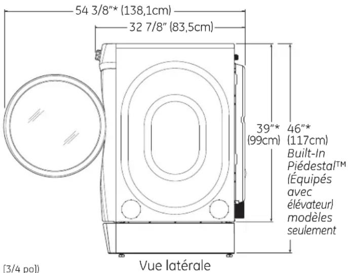
natural_image
Pure diagram of a three-way pipe fitting with no text or symbolsnatural_image
Technical line drawing of a mechanical component with a warning symbol (no text or labels)natural_image
Illustration of a hand connecting pipe fittings to a valve (no text or symbols present)□ Tuyau de raccordement souple
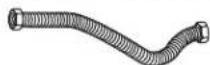
natural_image
Hand placing a button into an electrical control box (no text or symbols visible)natural_image
Simple line drawing of a trash bin with a downward arrow and a cigarette inside (no text or symbols)EXIGENCES RELATIVES AU GAZ ALIMENTATION EN GAZ

AVERTISSEMENT

natural_image
Illustration of hands connecting hoses to a vehicle hood (no text or symbols)RACCORDEMENT DE LA SÉCHEUSE À L'ALIMENTATION EN GAZ (suite)
natural_image
Illustration of hands connecting a mechanical pipe to a valve (no text or symbols)natural_image
Line drawing of a hand inserting a grid into an electrical outlet (no text or symbols)RENSEIGNEMENTS SUR LES RACCORDS ÉLECTRIQUES POUR SÉCHEUSES ÉLECTRIQUES
natural_image
Technical line drawing of a mechanical component with no visible text or symbolsnatural_image
Technical line drawing of a mechanical component with a triangular tool and directional arrow (no text or symbols)natural_image
Diagram of a computer with a CPU socket and cord, enclosed in a circle (no text or symbols)natural_image
Pure technical diagram of a mechanical component with no text, numbers, or symbolsÉVACUATION LATÉRALE (suite)
AJOUTER UN COUDE ET UN CONDUIT POUR L'ÉVACUATION SUR LA GAUCHE ET LA DROITE DE L'APPAREIL (suite)
text_image
Plaque (Ensemble WE49X22606)ÉVACUATION PAR LE DESSOUS (suite)
text_image
Portion "A" Fixing hole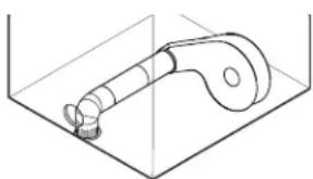
natural_image
Technical line drawing of a mechanical component with a curved arm and cylindrical body (no text or symbols)text_image
Plaque (Ensemble WE49X22606)natural_image
Illustration of a hand holding an electrical outlet with a plug, showing a grid pattern inside (no text or symbols)natural_image
Line drawing of a washing machine with internal components and close-up insets showing internal wiring (no text or symbols)text_image
Technical diagram showing a circular component with internal arrows and dimension labels (d, s) indicating measurement or force directions.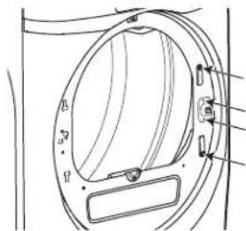
text_image
Technical diagram of a device with labeled components and directional arrows indicating motion or movement.natural_image
Technical line drawing of a circular mechanical component with radial and concentric features (no text or symbols)4 REPOSITIONNEMENT DU MASQUE DE PORTE
natural_image
Diagram of a circular structure with internal components and labeled 'APRÈS' (no other text or symbols)natural_image
Technical line drawing of a circular mechanical component with mounting holes and internal features (no text or symbols)natural_image
Technical line drawing of a circular mechanical component with mounting holes and internal features (no text or symbols)6 REMONTAGE DE LA PORTE
natural_image
Technical line drawing of a circular mechanical component with radial and concentric lines, no text or symbols present⑧ RÉINSTALLATION DE LA PORTE
text_image
Technical diagram of a washing machine with labeled components and close-up views showing internal structure details.7 REPOSITIONNEMENT DE LA VIS DE L'AXE DE CHARNIÈRE
natural_image
Line drawing of a washing machine with circular vent and side door (no text or symbols)natural_image
Technical line drawing of a mechanical component with a knob and dial (no text or symbols)2 COMMENT INSTALLER LES CALES EN CAOUTCHOUC SUR LA BASE DE LA SÉCHEUSE
natural_image
Technical line drawing of a mechanical component with an inset close-up view (no text or symbols)Garant : MC Commercial, Burlington, ON
Au Canada, contactez: Manager, Consumer Relations, MC Commercial
Suite 310, 1 Factory Lane
Moncton, N.B. E1C 9M3

Prolongation de garantie
Aux É.-U.: GEAppliances.com
GE Appliances, Appliance Park
Louisville, KY 40225
text_image
1 Power Steam Refresh 3 3 5-8 Tires Cottons Mixed Loods Quick Dry Towels Sheets Bulky Items Active Wear Sanitize Delicates Steam Dewrinkle Full Loads Warm Up Air Fluff Time Dry Add Time 7 18 19 64 Delay Dry Ride (Spare) (Lack) 9 Detangle eDry Eat Tumble Damp Alert Start/Pause 2 Light Volume 14 15 7 18 19 64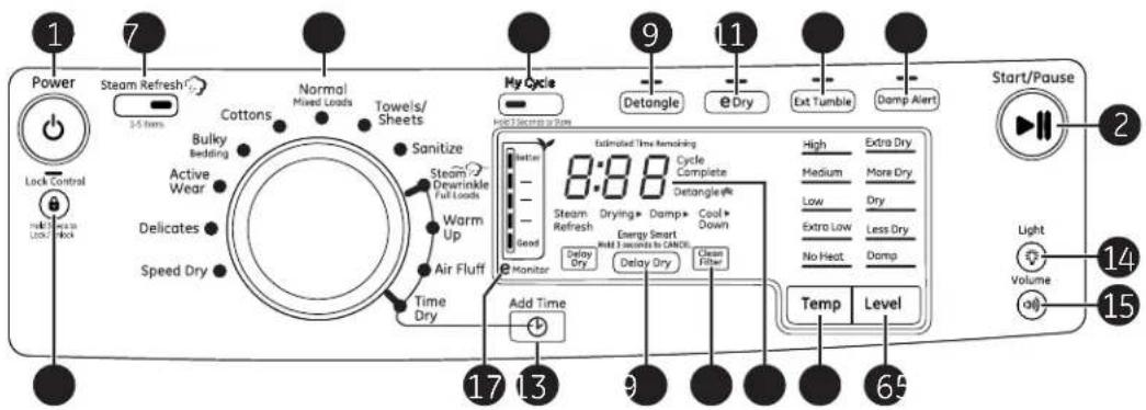
text_image
1 7 Power Steam Refresh 3-5 Tums Cottons Normal Mixed Loads Towels/ Sheets 9 11 My Cycle HOLD SEEDS TO ZONE Detangle Dry Ext Tumble Damp Alert Start/Pause 2 Lock Control Active Wear Delicates Speed Dry Bulky Bedding Sanitize Steam Dewrinkle Full Loads Warm Up Air Fluff Time Dry Better Estimated Time Remaining 8:00 Cycle Complete Steam Refresh Drying+ Damp+ Cool + Energy Smart Build 3 seconds to CANCE High Extra Dry Medium More Dry Low Dry Extra Low Less Dry No Heat Damp Monitor Delay Dry Delay Dry Clean Fiber Temp Level 17 13 9 6 14 Volume 90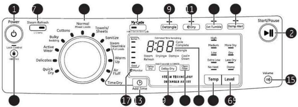
text_image
1 7 Power Steam Refresh 1-3 items Cottons Normal Mixed Loads Towels/ Sheets Active Wear Delicates Quick Dry Sanitize Steam Dewrinkle Full Loads Warm Up Air Fluff Time Dry My Cycle Hold a Second Time Cycle 9 Detangle eDry Ext Tumble Damp Alert Start/Pause 2 Volume 15 17 13 9 65 Add Time Estimated Time Remaining 8:88 Cycle Complete Delta Steam Refresh Drying+ Damp+ Cool + Down Good Monitor Delay Dry Delay Dry Clean Filter STEAM TECHNOLOGY DETANGLE AS LIST High Medium More Dry Low Dry Extra Low Less Dry No Heat Damp Temp Level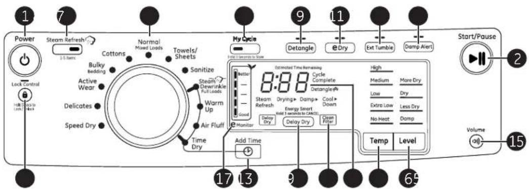
text_image
1 7 Power Steam Refresh 3.5 Tums Cottons Normal Mixed Loads Towels/ Sheets 9 My Cycle Detangle Dry Ext Tumble Damp Alert Start/Pause 2 Lock Control Active Wear Delicates Speed Dry Sanitize Steam/ Dewrinkle Full Loads Warm Up Air Fluff Time Dry Better 8:80 Cycle Complete Steam Refresh Drying/Damp Cool Energy Smart Down Hold 3 accents to CANCEL Monitor Delay Dry Delay Dry Clean Filter High Medium More Dry Low Dry Extra Low Less Dry No Heat Damp Temp Level Volume 15 Add Time 17 13 9 6Puesta en Marcha
natural_image
Technical line drawing of a mechanical assembly with no visible text or symbolsnatural_image
Technical line drawing of a mechanical component with circular opening and internal components (no text or symbols)natural_image
Technical line drawing of a washing machine handle and outlet (no text or symbols)La bombilla del tambor giratorio
natural_image
Line drawing of a front-loading washing machine with directional arrows indicating motion (no text or symbols)text_image
28" (71,12cm) 39"* 46"* (99cm) (117cm)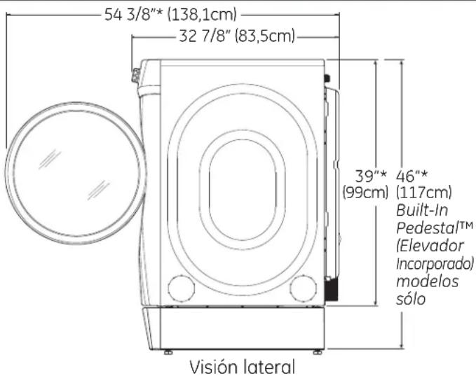
text_image
54 3/8"* (138,1cm) 32 7/8" (83,5cm) 39"* (99cm) 46"* (117cm) Built-In Pedestal™ (Elevador Incorporado) modelos sólo Visión lateralnatural_image
Pure diagram of a three-way pipe fitting with no text or symbolsnatural_image
Pure technical line drawing of a mechanical component with no text or symbolsnatural_image
Illustration of a hand holding a valve with curved arrows indicating direction (no text or symbols)natural_image
Hand placing a button into an electrical control box with multiple buttons (no text or symbols visible)natural_image
Simple line drawing of a trash bin with a downward arrow and a pencil inside (no text or symbols)natural_image
Illustration of hands adjusting a hose component on an air vent (no text or symbols)CÓMO CONECTAR LA SECADORA AL SUMINISTRO DE GAS (cont.)
natural_image
Illustration of hands connecting a mechanical pipe to a valve (no text or symbols present)natural_image
Line drawing of a hand holding an electrical outlet with wires (no text or symbols)natural_image
Technical line drawing of a mechanical component with no visible text or symbolsnatural_image
Diagram of a computer monitor with a cable and ventilation duct, enclosed in a circle (no text or symbols)natural_image
Pure technical diagram of a mechanical component with no visible text, numbers, or symbolstext_image
Placa (Kit WE49X22606)natural_image
Technical line drawing of a mechanical component with a curved arm and base, enclosed in a transparent container (no text or symbols)text_image
Placa (Kit WE49X22606)text_image
Elevar Bajar2 ENCHUFE LA SECADORA
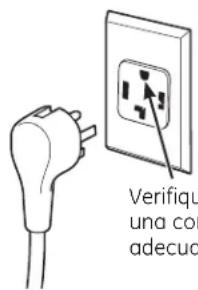
text_image
Verifique una co adecuonatural_image
Line drawing of a washing machine with internal components and close-up insets (no text or symbols)text_image
Technical diagram showing two views of a mechanical component with labeled parts and directional arrows indicating motion or force.text_image
Technical diagram showing two views of a mechanical component with labeled dimensions and directional arrows indicating motion or force.natural_image
Technical line drawing of a circular mechanical component with radial and concentric features (no text or symbols)text_image
ANTES DESPUÉSnatural_image
Technical line drawing of a circular mechanical component with mounting holes and internal features (no text or symbols)natural_image
Technical line drawing of a circular mechanical component with radial connections and mounting brackets (no text or symbols)⑧ VUELVA A INSTALAR EL ENSAMBLE DE LA PUERTA
natural_image
Line drawing of a washing machine with open door and internal components, showing close-up views (no text or symbols)7 VUELVA A COLOCAR EL TORNILLO CON CLAVIJA DE LA BISAGRA
natural_image
Line drawing of a washing machine with circular vent and side buttons (no text or symbols)GE Appliances, Appliance Park
Louisville, KY 40225