
CH 22EAP - Hedge Trimmers HITACHI - Free user manual and instructions
Find the device manual for free CH 22EAP HITACHI in PDF.
| Product type | Hedge trimmer |
| Brand | Hitachi |
| Model | CH 22EAP |
| Engine displacement | 21.1 ml |
| Fuel tank capacity | 0.30 L |
| Dry weight | 4.5 kg |
| Overall blade length | 500 mm |
| Blade type | Double-action blade |
| Sound pressure level LpA | 89 dB(A) |
| Sound power level LwA | 112 dB(A) |
| Vibration level (front handle) | 7.3 m/s² |
| Vibration level (rear handle) | 5.9 m/s² |
| Spark plug | NGK BMR 7A or Champion CJ 6 |
| Fuel | 2-stroke gasoline/oil mixture (25:1 to 50:1) |
| Main functions | Hedge cutting, multi-position pivoting handle (0°, 45°, 90°) |
| Maintenance | Air filter cleaning, blade gap adjustment, gearbox lubrication, spark plug cleaning |
| Safety | Safety glasses, hearing protection, gloves, keep 15 m away from bystanders |
| Spare parts | Hitachi genuine parts recommended |
Frequently Asked Questions - CH 22EAP HITACHI
User questions about CH 22EAP HITACHI
0 question about this device. Answer the ones you know or ask your own.
Ask a new question about this device
Download the instructions for your Hedge Trimmers in PDF format for free! Find your manual CH 22EAP - HITACHI and take your electronic device back in hand. On this page are published all the documents necessary for the use of your device. CH 22EAP by HITACHI.
USER MANUAL CH 22EAP HITACHI
CH 22EAP (50ST)/CH 22EA (50ST)/CH 22EBP (62ST) CH 22EB (62ST)/CH 22ECP (62ST)/CH 22EC (62ST) CH 22ECP (78ST)/CH 22EC (78ST)
natural_image
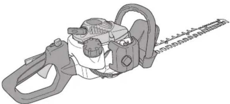
Illustration of a mechanical device with handle and gear (no text or symbols visible)CH22EBP (62ST)

Read the manual carefully before operating this machine. Lesen Sie vor der Verwendung diese Anleitung sorgfältig durch. Lire attentivement le manuel avant d'utiliser la machine. Leggere attentamente il manuale prima di mettere in funzione questa apparecchiatura. Lees de handleiding zorgvuldig door voordat u de machine bedient. Antes de utilizar esta máquina, lea cuidadosamente el manual. Leia o manual atentamente antes de operar esta máquina. Läs noga igenom bruksanvisningen innan maskinen tas i bruk. Læs denne brugsvejledning omhyggeligt, inden maskinen tages i brug. Bruksanvisningen må leses nøye før bruk av maskinen. Lue ohjekirja huolellisesti ennen koneen käyttämistä.
Handling instructions Bedienungsanleitung Mode d'emploi Istruzioni per l'uso Gebruiksaanwijzing Instrucciones de manejo
Instruções de uso Bruksanvisning Brugsanvisning Bruksanvisning Käyttöohjeet
natural_image
Illustration of hands using a tool to adjust or install a mechanical component (no text or symbols visible)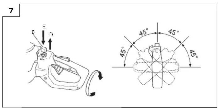
natural_image
Technical diagram showing a mechanical assembly with an arrow indicating a process (no text or symbols present)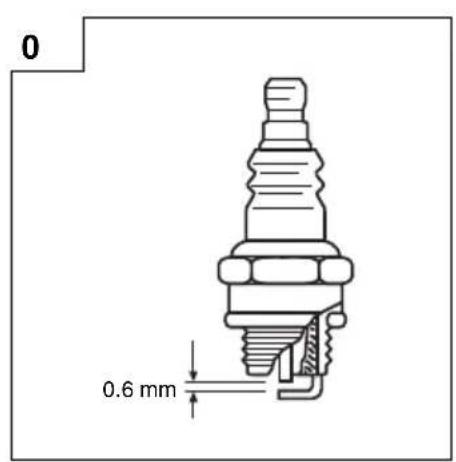
natural_image
Line drawing of a hand using a tool to work on a mechanical gear component (no text or symbols present)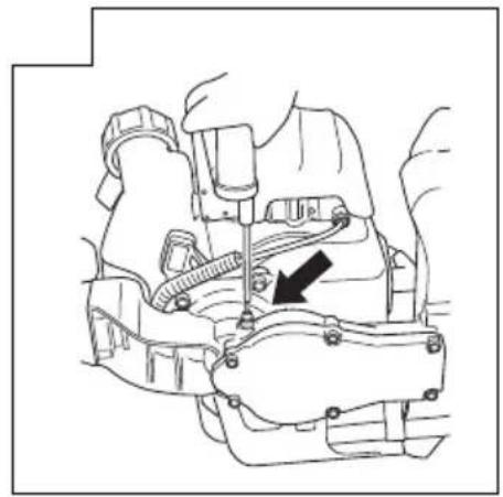
natural_image
Technical line drawing of a mechanical assembly with no visible text or symbols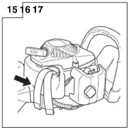

natural_image
Technical line drawing of a mechanical assembly with exploded view and labeled component (no text or symbols present)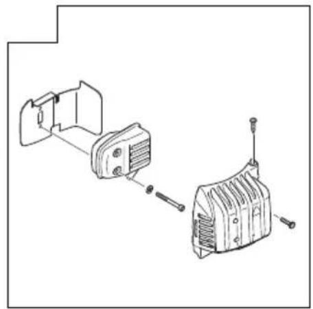
natural_image
Technical line drawing of a mechanical assembly with two views (top and side), no text or symbols presentMEANINGS OF SYMBOLS
NOTE: Some units do not carry them.
| Symbols⚠ WARNINGThe following show symbols used for the machine. Be sure that you understand their meaning before use. | |||
 | It is important that you read, fully understand and observe the following safety precautions and warnings. Careless or improper use of the unit may cause serious or fatal injury. | Always wear eye, head and ear protectors when using this unit. | |
 | Read, understand and follow all warnings and instructions in this manual and on the unit. | Before using your machine• Read the manual carefully.• Check that the cutting equipment is correctly assembled and adjusted.• Start the unit and check the carburetor adjustment.See “MAINTENANCE”. | |
Contents
WHAT IS WHAT? 4
WARNINGS AND SAFETY INSTRUCTIONS 5
SPECIFICATIONS 6
OPERATING PROCEDURES 6
MAINTENANCE....7
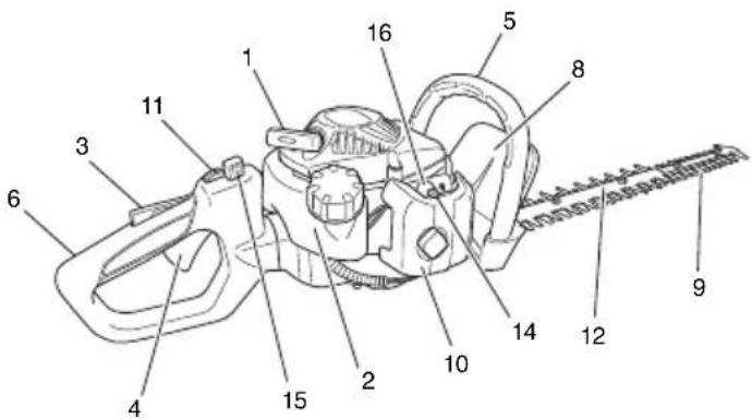
WHAT IS WHAT?
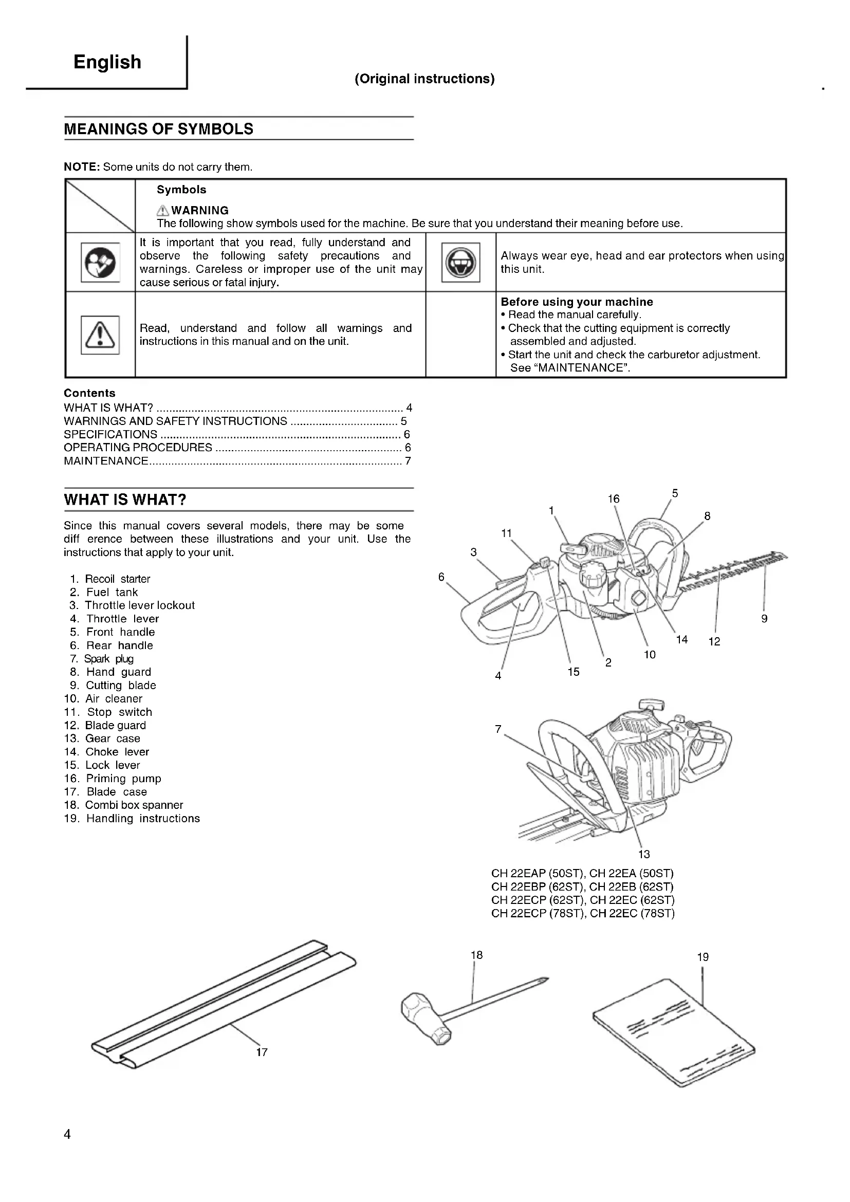
Since this manual covers several models, there may be some difference between these illustrations and your unit. Use the instructions that apply to your unit.
- Recoil starter
- Fuel tank
- Throttle lever lockout
- Throttle lever
- Front handle
- Rear handle
- Spark plug
- Hand guard
- Cutting blade
- Air cleaner
- Stop switch
- Blade guard
- Gear case
- Choke lever
- Lock lever
- Priming pump
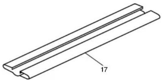
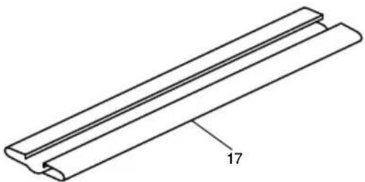
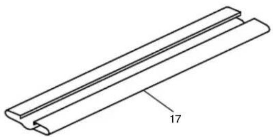
- Blade case
- Combi box spanner
- Handling instructions

CH 22EAP (50ST), CH 22EA (50ST)
CH 22EBP (62ST), CH 22EB (62ST)
CH 22ECP (62ST), CH 22EC (62ST)
CH 22ECP (78ST), CH 22EC (78ST)
natural_image
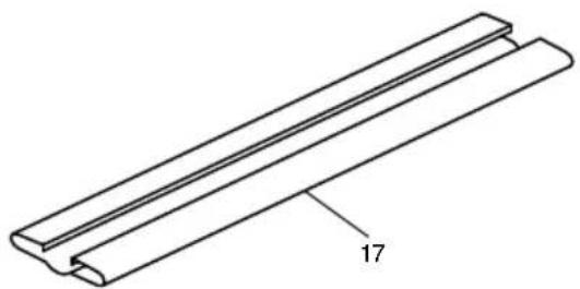
Technical line drawing of a three-layered mechanical component with a labeled dimension (17), no text or symbols present.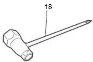
natural_image
Simple line drawing of a hammer with a pointed tip and labeled number 18 (no text or symbols on the object itself)
natural_image
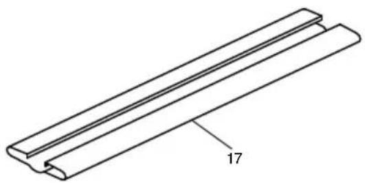
Isometric line drawing of a closed book with visible page lines and a small number 19 on top (no text or symbols on the pages)WARNINGS AND SAFETY INSTRUCTIONS
Keep for future reference.
THIS HEDGE TRIMMER CAN CAUSE SERIOUS INJURIES. Read the instructions carefully for the correct handling, preparation, maintenance, starting and stopping of the hedge trimmer. Become familiar with all controls and the proper use of the hedge trimmer.
Operator safety
○ Always wear a safety face shield or goggles.
○ Always wear heavy, long pants, boots and gloves. Do not wear loose clothing, jewelry, short pants, sandals or go barefoot. Secure hair so it is above shoulder length.
○ Do not operate this tool when you are tired, ill or under the influence of alcohol, drugs or medication.
Never let a child or inexperienced person operate the machine.
○ Beware of overhead power lines.
○ Wear hearing protection.
Never start or run the engine inside a closed room or building. Breathing exhaust fumes can kill.
○ Keep handles free of oil and fuel.
○ Keep hands away from cutting equipment.
○ Do not grab or hold the unit by the cutting equipment.
When the unit is turned off, make sure the cutting attachment has stopped before the unit is set down.
When operation is prolonged, take a break from time to time so that you may avoid possible Hand-Arm Vibration Syndrome (HAVS) which is caused by vibration.
☐ If the cutting mechanism strikes any foreign object or the hedge trimmer starts making any unusual noise or vibration, shut off the power source and allow the hedge trimmer to stop. Disconnect the spark plug wire from the spark plug and take the following steps:
- Inspect for damage;
- Check for, and tighten, any loose parts;
- Have any damaged parts replaced or repaired with parts having equivalent specifications.
WARNING
○ Antivibration systems do not guarantee that you will not sustain Hand-Arm Vibration Syndrome or carpal tunnel syndrome. Therefore, continual and regular users should monitor closely the condition of their hands and fingers. If any symptoms of the above appear, seek medical advice immediately.
☐ If you are using any medical electric/electronic devices such as a pacemaker, consult your physician as well as the device manufacturer prior to operating any power equipment.
When a foreign object is caught in the blade, turn off the engine, and remove the foreign object carefully using a plier etc., after the hedge trimmer has been cooled down. Be careful when removing the foreign object, since the blade may move because of the backlash.
Unit/machine safety
☐ Inspect the entire unit/machine before each use. Replace damaged parts. Check for fuel leaks and make sure all fasteners are in place and securely tightened.
○ Replace parts that are cracked, chipped or damaged in any way before using the unit/machine.
○ Keep others away when making carburetor adjustments.
○ Use only accessories as recommended for this unit/machine by the manufacturer.
WARNING
Never modify the unit/machine in any way. Do not use your unit/machine for any job except that for which it is intended.
Fuel safety
○ Mix and pour fuel outdoors and where there are no sparks or flames.
○ Use a container approved for fuel.
Never remove the fuel cap or add fuel with the power source running. Allow engine and exhaust components to cool down before refuelling.
○ Do not smoke or allow smoking near fuel or the unit/machine or while using the unit/machine.
○ Never refuel indoors.
○ Wipe up all fuel spills before starting engine.
○ Move at least 3 m away from fueling site before starting engine.
○ Stop engine before removing fuel cap.
Empty the fuel tank before storing the unit/machine. It is recommended that the fuel be emptied after each use. If fuel is left in the tank, store so fuel will not leak.
Store unit/machine and fuel in area where fuel vapors cannot reach sparks or open flames from water heaters, electric motors or switches, furnaces, etc.
WARNING
Fuel is easy to ignite or get explosion or inhale fumes, so that pay special attention when handling or filling fuel.
Cutting safety
○ Do not cut any material other than plant hedge.
○ Inspect the area to be cut before each use. Remove objects which can be thrown or become entangled.
☐ For respiratory protection, wear an aerosol protection mask when cutting the grass after insecticide is scattered.
Keep others including children, animals, bystanders and helpers outside the 15 m hazard zone. Stop the engine immediately if you are approached.
○ Hold the unit/machine firmly with both hands.
○ Keep firm footing and balance. Do not over-reach.
Keep all parts of your body away from the muffler and cutting attachment when the engine is running.
Keep cutting tool below shoulder level. NEVER operate unit from a ladder, while in a tree or from any unstable support.
○ When relocating to a new work area, be sure to shut off the machine and ensure that all cutting attachments are stopped.
○ Never place the machine on the ground when running.
○ Always carry a first-aid kit when operating any power equipment.
Never start or run the engine inside a closed room or building and/or near the inflammable liquid. Breathing exhaust fumes can kill.
Maintenance safety
○ Maintain the unit/machine according to recommended procedures.
○ Disconnect the spark plug before performing maintenance except for carburetor adjustments.
○ Keep others away when making carburetor adjustments.
○ Use only genuine Hitachi replacement parts as recommended by the manufacturer.
When the hedge trimmer is stopped for servicing, inspection or storage, shut off the power source, disconnect the spark plug wire from the spark plug and make sure all moving parts have come to a stop.
Allow the hedge trimmer to cool before making any inspection, adjustments, etc.
Transport and storage
○ Carry the unit/machine by hand with the engine stopped and the muffler away from your body.
○ Allow the engine to cool, empty the fuel tank, and secure the unit/machine before storing or transporting in a vehicle.
○ Empty the fuel tank before storing the unit/machine. It is recommended that the fuel be emptied after each use. If fuel is left in the tank, store so fuel will not leak.
○ Store unit/machine out of the reach of children.
○ Clean and maintenance the unit carefully and store it in a dry place.
○ Make sure engine switch is off when transporting or storing.
○ When transporting in a vehicle or storage, cover blade with blade cover.
If situations occur which are not covered in this manual, take care and use common sense. Contact your Hitachi dealer if you need assistance. Pay special attention to statements preceded by the following words:
WARNING
Indicates a strong possibility of severe personal injury or loss of life, if instructions are not followed.
CAUTION
Indicates a possibility of personal injury or equipment damage, if instructions are not followed.
NOTE
Helpful information for correct function and use.
CAUTION
Do not disassemble the recoil starter. you may get a possibility of personal injury with recoil spring.
SPECIFICATIONS
| MODEL | CH22EAP (50ST)CH22EA (50ST) | CH22EBP (62ST)CH22EB (62ST) | CH22ECP (62ST)CH22EC (62ST) | CH22ECP (78ST)CH22EC (78ST) |
| Engine Size (ml) 21.1 | ||||
| Spark Plug NGK BMR 7A (Europe and Australia) or Champion CJ 6 (other regions) | ||||
| Fuel Tank Capacity (l) 0.30 | ||||
| Dry Weight (kg) 4.5 4.8 5.3 5.5 | ||||
| Overall blade length (mm) 500 620 620 780 | ||||
| Blade type | 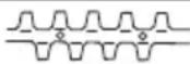 | |||
| Sound pressure levelLpA (dB(A)) (ISO 10517) 89 89 89 89 | ||||
| Sound power levelLw measured (dB (A)) (2000/14/EC) 108 108 108 108 | ||||
| LwA (dB (A)) 112 | ||||
| Vibration level (m/s ^2 ) (ISO 10517)Front handleRear handle | 7.35.9 | 14.87.4 | 2.62.8 | 2.62.8 |
NOTE
Equivalent noise level/vibration level are calculated as the time-weighted energy total for noise/vibration levels under various working conditions with the following time distribution: ISO 10517.....1/5 idle, 4/5 racing. 2000/14/EC.....only racing.
* All data subject to change without notice.
OPERATING PROCEDURES
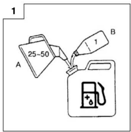
Fuel (Fig. 1)
WARNING
The hedge trimmer is equipped with a two-stroke engine. Always run the engine on fuel, mixed with oil.
Provide good ventilation, when fueling or handling fuel.
Fuel
○ Always use branded 89 octane unleaded gasoline.
○ Use genuine two-cycle oil or use a mix between 25:1 to 50:1, please consult the oil bottle for the ratio or Hitachi dealer.
☐ If genuine oil is not available, use an anti-oxidant added quality oil expressly labeled for air-cooled 2-cycle engine use (JASO FC GRADE OIL or ISO EGC GRADE). Do not use BIA or TCW (2-stroke water-cooling type) mixed oil.
○ Never use multi-grade oil (10W/30) or waste oil.
○ Always mix fuel and oil in a separate clean container.
Always start by filling half the amount of fuel, which is to be used. Then add the whole amount of oil. Mix (shake) the fuel mixture. Add the remaining amount of fuel.
Mix (shake) the fuel-mix thoroughly before filling the fuel tank.
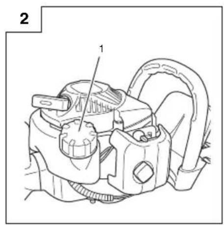
Fueling
WARNING (Fig. 2)
○ Always shut off the engine before refueling.
○ Slowly open the fuel tank (1), when filling up with fuel, so that possible over-pressure disappears.
○ Tighten the fuel cap carefully, after fueling.
○ Always move the unit at least 3 m from the fueling area before starting.
Before fueling, clean the tank cap area carefully, to ensure that no dirt falls into the tank. Make sure that the fuel is well mixed by shaking the container, before fueling.
Starting
CAUTION
Before starting, make sure the cutting attachment does not touch anything.
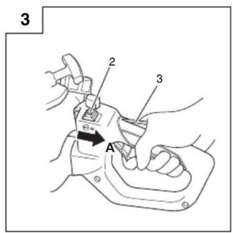
- Set stop switch (2) to ON position (A). (Fig. 3)
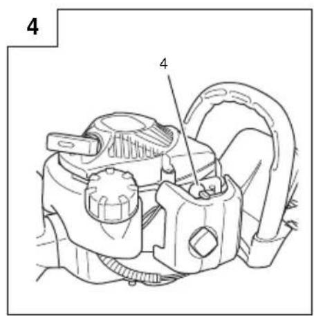
* Push priming pump (4) several times so that fuel flows through the pump or return pipe. (If so equipped) (Fig. 4) - With the throttle lever lockout (3) pressed, pull throttle lever, then slowly release the throttle lever first, then the throttle lever lockout. This will lock the throttle in starting position. (Fig. 3)
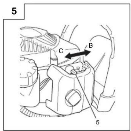
- Set choke lever (5) to CLOSED position (B). (Fig. 5)
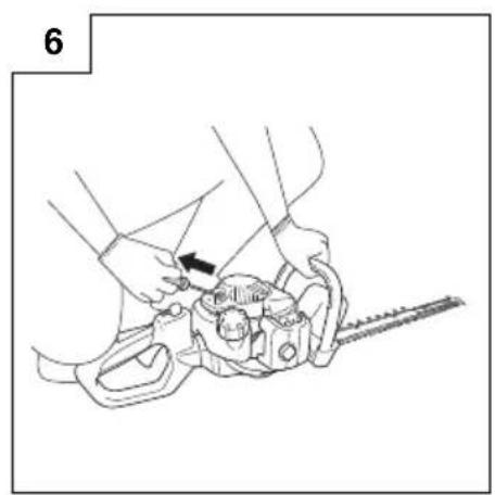
- Pull recoil starter briskly, taking care to keep the handle in your grasp and not allowing it to snap back. (Fig. 6)
- When you hear the engine attempts to start, return choke lever to RUN position (open) (C). Then pull recoil starter briskly again.
NOTE
If engine does not start, repeat procedures from 2 to 4.
- After starting engine, allow the engine about 2-3 minutes to warm up before subjecting it to any load.
Cutting
When cutting, operate engine at full throttle as this maintains proper blade speed. When trimming top of hedge, hold trimmer so blades are between 15 and 30 degrees from a horizontal position and swing trimmer in an arc toward edge of hedge to sweep cuttings off. When trimming sides of hedge, hold blade vertically and swing unit in an arc.
NOTE
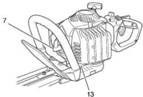
○ Multi-position twist handle (Fig. 7)
The rear control handle turns 90 degrees to provide comfortable use while accommodating a variety of cutting angles. The handle allows for five different locking positions. Before attempting to adjust rear handle, make sure the machine is at idle or engine is shut off.
☐ The machine will automatically shut off if the throttle lever is pressed while the handle is NOT secured in one of the five preset positions. Never attempt to operate the machine unless the rear handle is properly locked in place.
To rotate the handle; push the lock lever (6) allowing the handle to turn. Press the lock lever (6) to release the lock and allow the handle to turn. Rotate the handle to the desired 0°, 45° or 90° locking position and release the lock lever (6) to lock the handle in place.
D: LOCK
E: UNLOCK
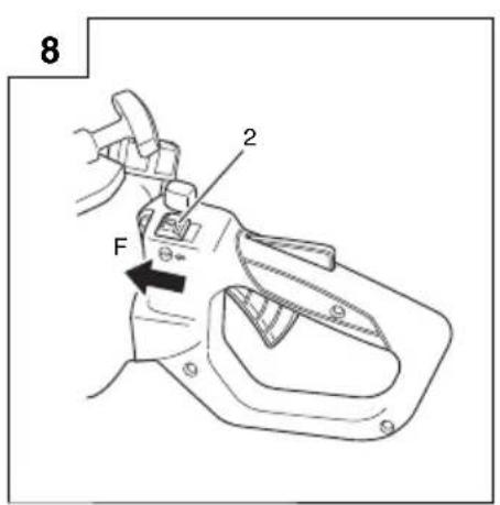
Stopping (Fig. 8)
Decrease engine speed, and push stop switch to stop position (F).
MAINTENANCE
MAINTENANCE, REPLACEMENT OR REPAIR OF THE EMISSION CONTROL DEVICES AND SYSTEM MAY BE PERFORMED BY ANY NONROAD ENGINE REPAIR ESTABLISHMENT OR INDIVIDUAL.
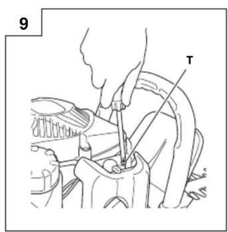
Carburetor adjustment (Fig. 9)
WARNING
○ The cutting attachment may be spinning during carburetor adjustments.
Never start the engine without the complete cleaner cover. Otherwise the clutch can come loose and cause personal injuries.
In the carburetor, fuel is mixed with air. When the engine is test run at the factory, the carburetor is adjusted. A further adjustment may be required, according to climate and altitude. The carburetor has one adjustment possibility:
T = Idle speed adjustment screw.
Idle speed adjustment (T)
Check that the air filter is clean. When the idle speed is correct, the cutting attachment will not rotate. If adjustment is required, close (clockwise) the T-screw, with the engine running, until the cutting attachment starts to rotate. Open (counter-clockwise) the screw until the cutting attachment stops. You have reached the correct idle speed when the engine runs smoothly in all positions well below the rpm when the cutting attachment starts to rotate.
If the cutting attachment still rotates after idle speed adjustment, contact Hitachi dealer.
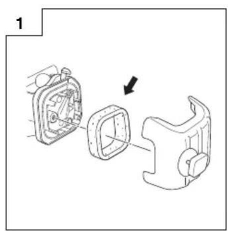
Air filter (Fig. 10)
The air filter must be cleaned from dust and dirt in order to avoid:
○ Carburetor malfunctions.
○ Starting problems.
○ Engine power reduction.
○ Unnecessary wear on the engine parts.
○ Abnormal fuel consumption.
Clean the air filter daily or more often if working in exceptionally dusty areas.
Cleaning the air filter
Remove the cleaner cover and the filter. Rinse it in warm soap suds. Check that the filter is dry before reassembly. An air filter that has been used for some time cannot be cleaned completely. Therefore, it must regularly be replaced by a new one. A damaged filter must always be replaced.
NOTE
Saturate the element in 2-cycle oil or the equivalent. Squeeze the element to distribute the oil completely and to remove any excess oil.
Spark plug (Fig. 11)
The spark plug condition is influenced by:
○ An incorrect carburetor setting.
○ Wrong fuel mixture (too much oil in the gasoline).
○ A dirty air filter.
○ Hard running conditions (such as cold weather).
These factors cause deposits on the spark plug electrodes, which may result in malfunction and starting difficulties. If the engine is low on power, difficult to start or runs poorly at idling speed, always check the spark plug first. If the spark plug is dirty, clean it and check the electrode gap. Readjust if necessary. The correct gap is 0.6 mm. The spark plug should be replaced after about 100 operation hours or earlier if the electrodes are badly eroded.
NOTE
In some areas, local law requires using a resistor spark plug to suppress ignition signals. If this machine was originally equipped with resistor spark plug, use the same type of spark plug for replacement.
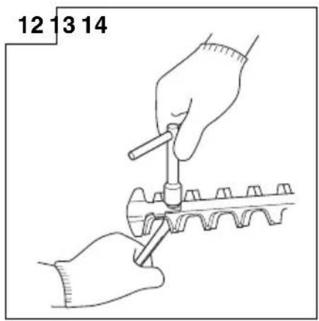
Cutting blade (Fig. 12, 13)
The blades are installed to the blade guide with the four, five or six bolts. Those bolts are tightened with a clearance so that the blades can move smoothly.
When clearance is too small
The blades do not move properly and the sliding surfaces may seize.
When clearance is too large
The blades are poor in sharpness.
To adjust the blade clearance
- Loosen the blade fixing nuts.
- Fully tighten the blade fixing bolts and then loosen them approx. 3/8 turn.
- With the bolts set at that position, tighten the blade fixing nuts. Be sure to replace blade guide fixing bolts when they are loosened, worn or damaged. Also be sure to replace damaged cutter blade.
NOTE
Properly lubricate the blade sliding surfaces with machine oil.
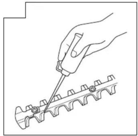
Gear case (Fig. 14)
Apply a good quality lithium based grease through the grease fitting until a small amount comes out between the cutting blades and the gear case. Lubricate the grease from the grease nipple (indicated by an arrow) next to the gear case using a commercially available cartridge grease gun.
NOTE
Lubrication should be applied 3g at 20 hour intervals and more frequently with heavy use.
Fuel filter (Fig. 15)
Remove the fuel filter from the fuel tank and thoroughly wash it in solvent. After that, push the filter into the tank completely.
NOTE
If the filter is hard due to dust and dirt, replace it.
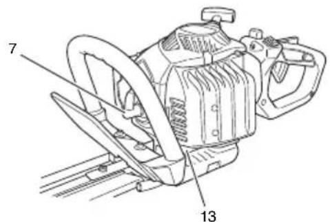
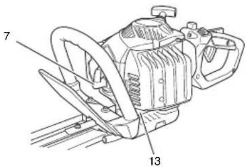
Cleaning the cylinder fins (Fig. 16)
When leaves get caught between cylinder fins (7), the engine may overheat, resulting in lower output. To avoid this, always keep cylinder fins and cylinder cover clean.
Every 100 operating hours, or once a year (more often if conditions require), clean fins and external surfaces of engine of dust, dirt and oil deposits which can contribute to improper cooling.
Cleaning the muffler (Fig. 17)
Remove the muffler and spark arrestor (if so equipped), and clean out any excess carbon from the exhaust port or muffler inlet every 100 hours of operation.
For long-term storage
Drain all fuel from the fuel tank. Start and let engine run until it stops. Repair any damage which has resulted from use. Clean the unit with a clean rag, or high pressure air hose. Put a few drops of two-cycle engine oil into the cylinder through the spark plug hole, and spin the engine over several times to distribute oil. Cover the unit and store it in a dry area.
Maintenance schedule
Below you will find some general maintenance instructions. For further information please contact your Hitachi dealer.
Daily maintenance
○ Clean the exterior of the hedge trimmer.
○ Check the blade guide for damage or cracks. Change the guard in case of impacts or cracks.
○ Check that the blade is sharp, and without cracks.
○ Check that the blade nut is sufficiently tightened.
○ Make sure that the blade blunt guard is undamaged and that it can be securely fitted.
○ Check that nuts and screws are sufficiently tightened.
Weekly maintenance
○ Check the starter, especially cord and return spring.
○ Clean the exterior of the spark plug.
○ Remove it and check the electrode gap. Adjust it to 0.6 mm, or change the spark plug.
○ Clean the cooling fins on the cylinder and check that the air intake at the starter is not clogged.
○ Check gear case is filled with grease.
○ Clean the air fi Iter.
Monthly maintenance
○ Rinse the fuel tank with gasoline.
○ Clean the exterior of the carburetor and the space around it.
○ Clean the fan and the space around it.
CH 22EAP (50ST), CH 22EA (50ST)
CH 22EBP (62ST), CH 22EB (62ST)
CH 22ECP (62ST), CH 22EC (62ST)
CH 22ECP (78ST), CH 22EC (78ST)
natural_image
Technical line drawing of a three-layered mechanical component with labeled dimension (17), no text or symbols present.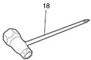
natural_image
Line drawing of a hammer with a labeled end (18), no text or symbols present
natural_image
Simple line drawing of a closed book with visible page lines and a small number 19 on the top right corner (no text or symbols on the pages themselves)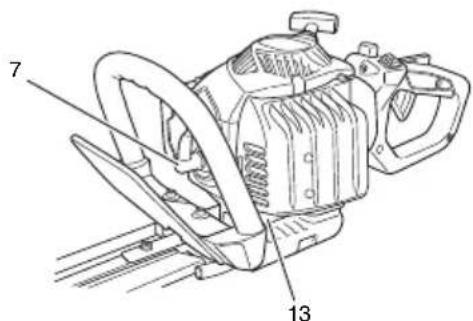
CH 22EAP (50ST), CH 22EA (50ST)
CH 22EBP (62ST), CH 22EB (62ST)
CH 22ECP (62ST), CH 22EC (62ST)
CH 22ECP (78ST), CH 22EC (78ST)
natural_image
Technical line drawing of a three parallel mechanical component with a labeled dimension (17), no text or symbols present.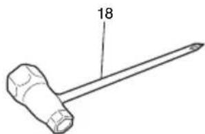
natural_image
Line drawing of a hammer with a labeled end (18), no text or symbols present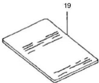
natural_image
Illustration of a closed book with visible page lines and a small number 19 on the right side (no text or symbols on the pages)PRÉCAUTIONS ET CONSIGNES DE SÉCURITÉ

CH 22EAP (50ST), CH 22EA (50ST)
CH 22EBP (62ST), CH 22EB (62ST)
CH 22ECP (62ST), CH 22EC (62ST)
CH 22ECP (78ST), CH 22EC (78ST)
natural_image
Technical line drawing of a three-layered mechanical component with labeled dimension (17), no text or symbols present.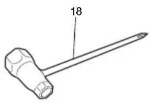
natural_image
Line drawing of a hammer with a labeled end (18), no text or symbols present
natural_image
Simple line drawing of a closed book with visible page lines and a small number 19 on the top right corner (no text or symbols on the book itself)AVVERTENZE ED ISTRUZIONI DI SICUREZZA
WAARSCHUWINGEN EN VEILIGHEIDSINSTRUCTIES ....25
SPECIFICATIES....26
BEDIENING 26
ONDERHOUD 27
WAT IS WAT?

CH 22EAP (50ST), CH 22EA (50ST)
CH 22EBP (62ST), CH 22EB (62ST)
CH 22ECP (62ST), CH 22EC (62ST)
CH 22ECP (78ST), CH 22EC (78ST)
natural_image
Technical line drawing of a three-layered mechanical component with a labeled dimension (17), no text or symbols present.
natural_image
Line drawing of a hammer with a labeled end (18), no text or symbols present
natural_image
Isometric line drawing of a closed book with visible page lines and cover (no text or symbols)WAARSCHUWINGEN EN VEILIGHEIDSINSTRUCTIES
⚠ WAARSCHUWING (Afb. 2)

CH 22EAP (50ST), CH 22EA (50ST)
CH 22EBP (62ST), CH 22EB (62ST)
CH 22ECP (62ST), CH 22EC (62ST)
CH 22ECP (78ST), CH 22EC (78ST)

natural_image
Technical line drawing of a three-layered mechanical component with labeled dimension (17), no text or symbols present.
natural_image
Line drawing of a hammer with a labeled end (18), no text or symbols present
natural_image
Isometric line drawing of a rectangular object with horizontal lines and a label '19' pointing to its top edge (no other text or symbols)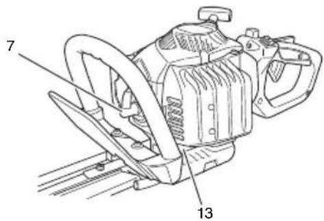
CH 22EAP (50ST), CH 22EA (50ST)
CH 22EBP (62ST), CH 22EB (62ST)
CH 22ECP (62ST), CH 22EC (62ST)
CH 22ECP (78ST), CH 22EC (78ST)

natural_image
Technical line drawing of a three-layered mechanical component with a labeled dimension (17), no text or symbols present.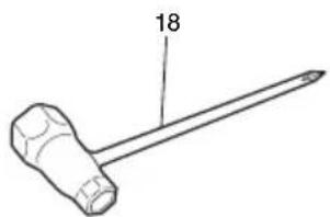
natural_image
Line drawing of a hammer with a labeled end (18), no text or symbols present
natural_image
Simple line drawing of a closed book with visible page lines and a small number 19 on the top right corner (no text or symbols on the book itself)ADVERTÊNCIAS E AVISOS DE SEGURANÇA
CH 22EAP (50ST), CH 22EA (50ST)
CH 22EBP (62ST), CH 22EB (62ST)
CH 22ECP (62ST), CH 22EC (62ST)
CH 22ECP (78ST), CH 22EC (78ST)
natural_image
Technical line drawing of a three-layered mechanical component with labeled dimension (17), no text or symbols present.
natural_image
Line drawing of a hammer with a labeled end (18), no text or symbols present
natural_image
Simple line drawing of a closed book with visible page lines and a small number 19 on the top right corner (no text or symbols on the pages themselves)VARNINGAR OCH SÄKERHETSINSTRUKTIONER
CH 22ECP (78ST), CH 22EC (78ST)

natural_image
Technical line drawing of a three-layered mechanical component with a labeled dimension (17), no text or symbols present.
natural_image
Simple line drawing of a hammer with a labeled end (18), no text or symbols present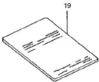
natural_image
Simple line drawing of a closed book with visible page lines and a small number 19 on the top right corner (no text or symbols on the pages themselves)ADVARSLER OG SIKKERHEDSINSTRUKTIONER

CH 22EAP (50ST), CH 22EA (50ST)
CH 22EBP (62ST), CH 22EB (62ST)
CH 22ECP (62ST), CH 22EC (62ST)
CH 22ECP (78ST), CH 22EC (78ST)

natural_image
Technical line drawing of a three-layered mechanical component with a labeled dimension (17), no text or symbols present.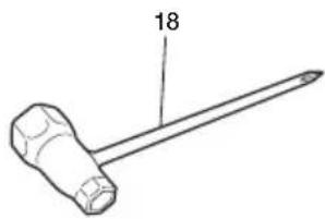
natural_image
Line drawing of a hammer with a labeled end (18), no text or symbols present
natural_image
Simple line drawing of a closed book with visible page lines and a small number 19 on the top right corner (no text or symbols on the pages themselves)ADVARSLER OG SIKKERHETSINSTRUKSJONER
○ Feil forgasserinnstilling.
○ Feil brennstoffblanding (for mye olje i bensinen)
○ Et tilsmusset luftfi Iter.
CH 22EAP (50ST), CH 22EA (50ST)
CH 22EBP (62ST), CH 22EB (62ST)
CH 22ECP (62ST), CH 22EC (62ST)
CH 22ECP (78ST), CH 22EC (78ST)

natural_image
Technical line drawing of a two-layered mechanical component with a labeled dimension (17), no text or symbols present.
natural_image
Line drawing of a hammer with a labeled end (18), no text or symbols present
natural_image
Isometric line drawing of a rectangular object with internal horizontal lines and a label '19' pointing to its top right corner (no other text or symbols)VAROITUKSET JA TURVALLISUUSOHJEET
natural_image
Line drawing of a quill pen with inkwell (no text or symbols)CH22EAP
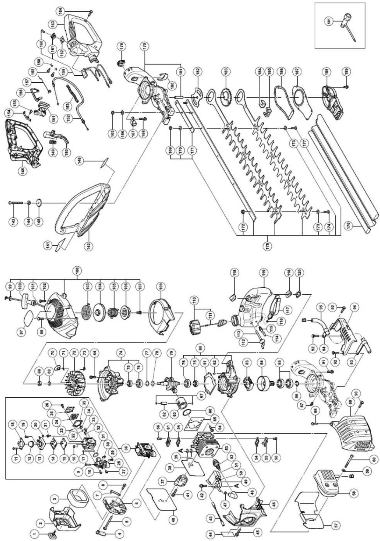
CH22EAP
| Item No. | Part Name Q'TY | |
| 1 | COVER FIXING BOLT COMP | 1 |
| 2 | C L E A N E | R |
| 3 | C L E A N E | R |
| 4 | C H O K E | V A |
| 5 | MACHINE SCREW (W/WASHERS) M5×60 | 2 |
| 6 | C L E A N E | R |
| 7 | C H O K E | H A |
| 8 | TAPPING SCREW (W/FLANGE) D4×12 | 1 |
| 9 | T S C R E W | ( |
| 10 | SCREW (B) 3 | |
| 11 | SCREW (D) 4 | |
| 12 | SYRINGE 1 | |
| 13 | PRIMER BASE ASS'Y 1 | |
| 14 | PUMP GASKET | 1 |
| 15 | PUMP DIAPHRAGM | 1 |
| 16 | STRAINER | 1 |
| 17 | GUIDE PIN ROLLER | 1 |
| 18 | SYRINGE RETAINER | 1 |
| 19 | SCREW (E) | 1 |
| 20 | BALL PLUG RETAINER | 1 |
| 21 | SCREW (MAIN MIXTURE) | 1 |
| 22 | METERING LEVER SPRING | 1 |
| 23 | PIN | 1 |
| 24 | METERING DIAPHRAGM ASS'Y | 1 |
| 25 | METERING COVER | 1 |
| 26 | SCREW (METERING COVER) | 2 |
| 27 | POST | 1 |
| 28 | ROTOR COVER ASS'Y | 1 |
| 29 | SCREW (C) | 1 |
| 30 | RETAINING RING (E-TYPE) D2.3 | 1 |
| 31 | O-RING | 1 |
| 32 | INLET NEEDLE VALVE 1 | |
| 33 | SCREW (A) | 1 |
| 34 | METERING LEVER | 1 |
| 35 | METERING GASKET 1 | |
| 36 | CARBURETOR ASS'Y | 1 |
| 37 | CARBURETOR INSULATOR | 1 |
| 38 | INTAKE PACKING | 1 |
| 39 | GLASS WASHER | 4 |
| 40 | CARBURETOR PACKING | 1 |
| 41 | SEAL LOCK HEX. SOCKET BOLT (W/WASHERS) M5 | 2 |
| 42 | HEX. SOCKET HD. BOLT (W/WASHERS) M4×18 | 2 |
| 43 | CORD | 1 |
| 44 | CAUTION LABEL | 1 |
| 45 | SEAL LOCK HEX. SOCKET HD. BOLT M4×12 | 1 |
| 46 | CYLINDER COVER | 1 |
| 47 | METAL FITTING OF PLUG CAP | 1 |
| 48 | PLAG CAP | 1 |
| 49 | CORD INSULATION TUBE | 1 |
| 50 | BAND | 1 |
| 51 | IGNITION COIL | 1 |
| 52 | SPARK PLUG | 1 |
| 53 | CYLINDER | 1 |
| 54 | COVER PACKING | 2 |
| 55 | INTAKE COVER (A) | 1 |
| Item No. | Part Name Q'TY | |
| 56 | SEAL LOCK SCREW M4×10 | 4 |
| 67 | CHEATPROEECTRON PANEL | 1 |
| S8 | RMUFICLER NSS'YG E 1 | 1 |
| 59 | WOLTEWASHER M6 2 | |
| 60 | HEX. SOCKET HD. BOLT M6×55 | 2 |
| B1 | ONTAKE COVER (B) | 1 |
| 62 | PISTON PINE 1 | 1 |
| 63 | PISTON | 1 |
| 64 | HEX. SOCKET HD. BOLT A(W/S8.WASHER) M5×18 | 8 |
| 65 | CYLINDER PACKING | 1 |
| 66 | PISTON RING | 1 |
| 67 | PISTON PIN CIR CLIP | 2 |
| 68 | FLYWHEEL NUT | 1 |
| 69 | BOLT WASHER D7 1 | |
| 70 | STARTER PAWL | 2 |
| 71 | STARTER PAWL SPRING | 2 |
| 72 | MAGNETO ROTOR | 1 |
| 73 | RETAINING RING D4 | 2 |
| 74 | CRANK CASE (B) ASS'Y 1 | |
| 75 | OIL SEAL TB 12227 | 2 |
| 76 | BALL BEARING 6001C3 | 2 |
| 77 | SHIM T0.2 | 1 |
| 78 | SHIM T0.3 | 1 |
| 79 | CRANK SHAFT | 1 |
| 80 | CRANK CASE (A) ASS'Y 1 | |
| 81 | CRANK CASE PACKING | 1 |
| 82 | KNOCK PIN 4×12 | 2 |
| 83 | CLUTCH (B) | 1 |
| 84 | CLUTCH DRUM | 1 |
| 85 | BALL BEARING 6002ZC3 | 2 |
| 86 | RETAINING RING FOR D15 SHAFT | 1 |
| 87 | GREASE NIPPLE COMP. | 1 |
| 88 | TAPPING SCREW (W/FLANGE) D5×20 | 1 |
| 89 | MUFFLER PROTECTOR | 1 |
| 90 | MACHINE SCREW (W/WASHERS) M5×16 | 1 |
| 91 | HEX. HOLE BOLT 6×18/S | 3 |
| 92 | HEX. SOCKET HD. BOLT (W/BUTTON) M5×20 | 3 |
| 93 | FIXATION PLATE (A) | 1 |
| 94 | FIXATION PLATE (B) | 1 |
| 95 | TAIL PIPE(A) | 1 |
| 96 | EXHAUST COVER | 1 |
| 97 | HITACHI LABEL | 1 |
| 98 | TAPPING SCREW D4.5×16 | 1 |
| 99 | PLATE | 1 |
| 100 | STARTER KNOB | 1 |
| 101 | STARTER ROPE | 1 |
| 102 | HEX. SOCKET HD. BOLT (W/BUTTON) M5×20 | 3 |
| 103 | RECOIL SPRING | 1 |
| 104 | STARTER ROPE REEL 1 | |
| 105 | DAMPER SPRING | 1 |
| 106 | CAM PLATE | 1 |
| 107 | SET SCREW | 1 |
| 108 | RECOIL STARTER | 1 |
| 109 | AIR DEFLECTOR | 1 |
| 110 | FUEL TANK CAP ASS'Y | 1 |
| 111 | TANK CAP CHAIN | 1 |
| Item No. | Part Name Q'TY | |
| 112 | FUEL GROMMET | 1 |
| 113 | FUEL PIPE | 1 |
| 114 | FUEL PIPE (PINK) | 1 |
| 115 | RETURN GROMMET | 1 |
| 116 | CLIP | 1 |
| 117 | PUMP FILTER | 1 |
| 118 | CUSHION RUBBER | 4 |
| 119 | TANK | 1 |
| 120 | HEAT PROTECTION PANEL (A) | 2 |
| 141 | NAME PLATE | 1 |
| 142 | HANDLE | 1 |
| 143 | SEAL LOCK HEX. SOCKET HD. BOLT M5×40 | 2 |
| 144 | SPRING LOCK WASHER D5 | 2 |
| 145 | BRAKE AXIS WASHER | 2 |
| 146 | HANDLE (A) | 1 |
| 148 | CAUTION LABEL | 1 |
| 149 | SPRING (A) 1 | |
| 150 | LOCK LEVER | 1 |
| 151 | THROTTLE LEVER 1 | |
| 152 | THROTTLE WIRE | 1 |
| 153 | PROTECTION TUBE | 1 |
| 154 | EARTH TERMINAL 1 | |
| 155 | TAPPING SCREW D3 3 | |
| 156 | TRIGGER LOCKOUT | 1 |
| 157 | THROTTLE LEVER SPRING | 1 |
| 158 | TAB TERMINAL | 2 |
| 159 | STOP SWITCH (A) | 1 |
| 160 | SCREW M3×10 | 1 |
| 161 | STOP BUTTON(RED) 1 | |
| 162 | STOP BUTTON MARK | 1 |
| 163 | HANDLE B | 1 |
| 164 | TAPPING SCREW (W/FLANGE) D4×16 | 4 |
| 165 | NYLON NUT M5 | 2 |
| 166 | SMALL WASHER 5 2 | |
| 167 | FIXATION PLATE (B) | 1 |
| 168 | HEX. SOCKET HD. BOLT (W/FLANGE) M6×22 | 1 |
| 169 | NYLON NUT M6 | 1 |
| 170 | BOLT WASHER D6 | 1 |
| 171 | SUPPORT PLATE | 1 |
| 172 | U- NUT M6 3 | |
| 173 | WASHER D7 | 4 |
| 174 | BOLT (B) | 3 |
| 175 | BLADE ASS'Y (A) | 1 |
| 176 | BLADE CASE (A) | 1 |
| 177 | BOLT (A) | 1 |
| 178 | GEAR CASE B | 1 |
| 179 | GEAR CASE (A) ASS'Y 1 | |
| 180 | CLIP | 1 |
| 181 | GEAR SHAFT | 1 |
| 182 | GUIDE PLATE | 1 |
| 183 | GEAR 2 | 1 |
| 184 | HOLDING PLATE | 1 |
| 185 | GREASE STOP A | 2 |
| 186 | GEAR CASE GASKET | 1 |
| 187 | GEAR CASE COVER | 1 |
| 188 | GEAR CASE B | 1 |
| 189 | HEX. SOCKET HD. BOLT (W/WASHERS) M4×18 | 6 |
| 501 | BOX WRENCH 10/19MM | 1 |
CH22EA
CH22EA
| Item No. | Part Name Q'TY | |
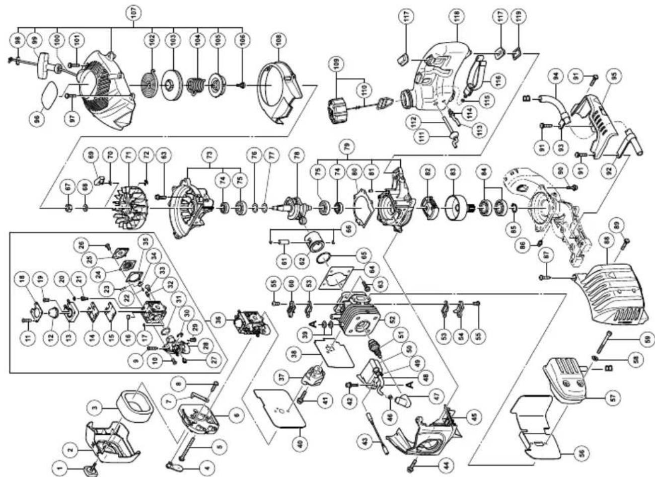
| 1 | COVER FIXING BOLT COMP | 1 |
| 2 | C L E A N E R C | |
| 3 | C L E A N E R S | |
| 4 | C H O K E V A L | |
| 5 | MACHINE SCREW (W/WASHERS) M5×60 | 2 |
| 6 | C L E A N E R B | |
| 7 | C H O K E H A N | |
| 8 | TAPPING SCREW (W/FLANGE) D4×12 | 1 |
| 9 | S C R E W ( T A | |
| 10 | SCREW (B) 3 | |
| 11 | SCREW (D) 4 | |
| 12 | SYRINGE 1 | |
| 13 | PRIMER BASE ASS'Y 1 | |
| 14 | PUMP GASKET 1 | |
| 15 | PUMP DIAPHRAGM 1 | |
| 16 | STRAINER 1 | |
| 17 | GUIDE PIN ROLLER 1 | |
| 18 | SYRINGE RETAINER 1 | |
| 19 | SCREW (E) 1 | |
| 20 | RETAINER (BALL PLUG) 1 | |
| 21 | SCREW (MAIN MIXTURE) 1 | |
| 22 | METERING LEVER SPRING 1 | |
| 23 | PIN 1 | |
| 24 | METERING DIAPHRAGM ASS'Y 1 | |
| 25 | METERING COVER 1 | |
| 26 | SCREW (C) 3 | |
| 27 | POST 1 | |
| 28 | ROTOR COVER ASS'Y 1 | |
| 29 | SCREW (C) 1 | |
| 30 | RETAINING RING (E-TYPE) D2.3 1 | |
| 31 | O-RING 1 | |
| 32 | INLET NEEDLE VALVE 1 | |
| 33 | SCREW (A) 1 | |
| 34 | METERING LEVER 1 | |
| 35 | METERING GASKET 1 | |
| 36 | CARBURETOR ASS'Y 1 | |
| 37 | CARBURETOR INSULATOR 1 | |
| 38 | INTAKE PACKING 1 | |
| 39 | GLASS WASHER 4 | |
| 40 | CARBURETOR PACKING 1 | |
| 41 | SEAL LOCK HEX. SOCKET BOLT (W/WASHERS)M5 2 | |
| 42 | HEX. SOCKET HD. BOLT (W/WASHERS) M4×18 2 | |
| 43 | CORD 1 | |
| 44 | SEAL LOCK HEX. SOCKET HD. BOLT M4×12 1 | |
| 45 | CYLINDER COVER 1 | |
| 46 | METAL FITTING OF PLUG CAP 1 | |
| 47 | PLAG CAP 1 | |
| 48 | CORD INSULATION TUBE 1 | |
| 49 | BAND 1 | |
| 50 | IGNITION COIL 1 | |
| 51 | SPARK PLUG 1 | |
| 52 | CYLINDER 1 | |
| 53 | COVER PACKING 2 | |
| 54 | INTAKE COVER (A) 1 | |
| 55 | SEAL LOCK SCREW M4×10 4 |
| Item No. | Part Name Q'TY | |
| 56 | HEAT PROTECTION PANEL | 1 |
| C57 | VMUEFLER ASS'Y | 1 |
| P58 | OBOINT WASHER M612 | |
| V59 | EHEXI SOCKET HD. BOLT M6×55 | 2 |
| 60 | INTAKE COVER (B) | 1 |
| C61 | DPISTON PIN | 1 |
| B2 | PISTON 1 | 1 |
| 63 | HEX. SOCKET HD. BOLT (W/SP.WASHER) M5×18 | 8 |
| S64 ) | CYLINDER PACKING | 1 |
| 65 | PISTON RING | 1 |
| 66 | PISTON PIN CIR CLIP | 2 |
| 67 | FLYWHEEL NUT | 1 |
| 68 | BOLT WASHER D7 | 1 |
| 69 | STARTER PAWL | 2 |
| 70 | STARTER PAWL SPRING | 2 |
| 71 | MAGNETO ROTOR | 1 |
| 72 | RETAINING RING D4 | 2 |
| 73 | CRANK CASE (B) ASS'Y | 1 |
| 74 | OIL SEAL TB 12227 | 2 |
| 75 | BALL BEARING 6001C3 | 2 |
| 76 | SHIM T0.2 | 1 |
| 77 | SHIM T0.3 | 1 |
| 78 | CRANK SHAFT | 1 |
| 79 | CRANK CASE (A) ASS'Y | 1 |
| 80 | CRANK CASE PACKING | 1 |
| 81 | KNOCK PIN 4×12 | 2 |
| 82 | CLUTCH (B) | 1 |
| 83 | CLUTCH DRUM | 1 |
| 84 | BALL BEARING 6002ZC3 | 2 |
| 85 | RETAINING RING FOR D15 SHAFT | 1 |
| 86 | GREASE NIPPLE COMP. | 1 |
| 87 | TAPPING SCREW (W/FLANGE) D5×20 | 1 |
| 88 | MUFFLER PROTECTOR | 1 |
| 89 | SCREW (W/WASHERS) M5×16 | 1 |
| 90 | HEX. HOLE BOLT 6×18/S | 3 |
| 91 | HEX. SOCKET HD. BOLT (W/BUTTON) M5×20 | 3 |
| 92 | FIXATION PLATE (A) 1 | |
| 93 | FIXATION PLATE (B) | 1 |
| 94 | TAIL PIPE(A) | 1 |
| 95 | EXHAUST COVER | 1 |
| 96 | HITACHI LABEL | 1 |
| 97 | TAPPING SCREW D4.5×16 | 1 |
| 98 | PLATE | 1 |
| 99 | STARTER KNOB | 1 |
| 100 | STARTER ROPE | 1 |
| 101 | HEX. SOCKET HD. BOLT (W/BUTTON) M5×20 | 3 |
| 102 | RECOIL SPRING | 1 |
| 103 | STARTER ROPE REEL | 1 |
| 104 | DAMPER SPRING | 1 |
| 105 | CAM PLATE | 1 |
| 106 | SET SCREW | 1 |
| 107 | RECOIL STARTER | 1 |
| 108 | AIR DEFLECTOR | 1 |
| 109 | FUEL TANK CAP ASS'Y 1 | |
| 110 | TANK CAP CHAIN | 1 |
| 111 | FUEL GROMMET | 1 |
| 112 | FUEL PIPE | 1 |
| Item No. | Part Name Q'TY | |
| 113 | FUEL PIPE (PINK) | 1 |
| 114 | RETURN GROMMET | 1 |
| 115 | CLIP | 1 |
| 116 | PUMP FILTER | 1 |
| 117 | CUSHION RUBBER | 4 |
| 118 | TANK | 1 |
| 119 | HEAT PROTECTION PANEL (A) | 2 |
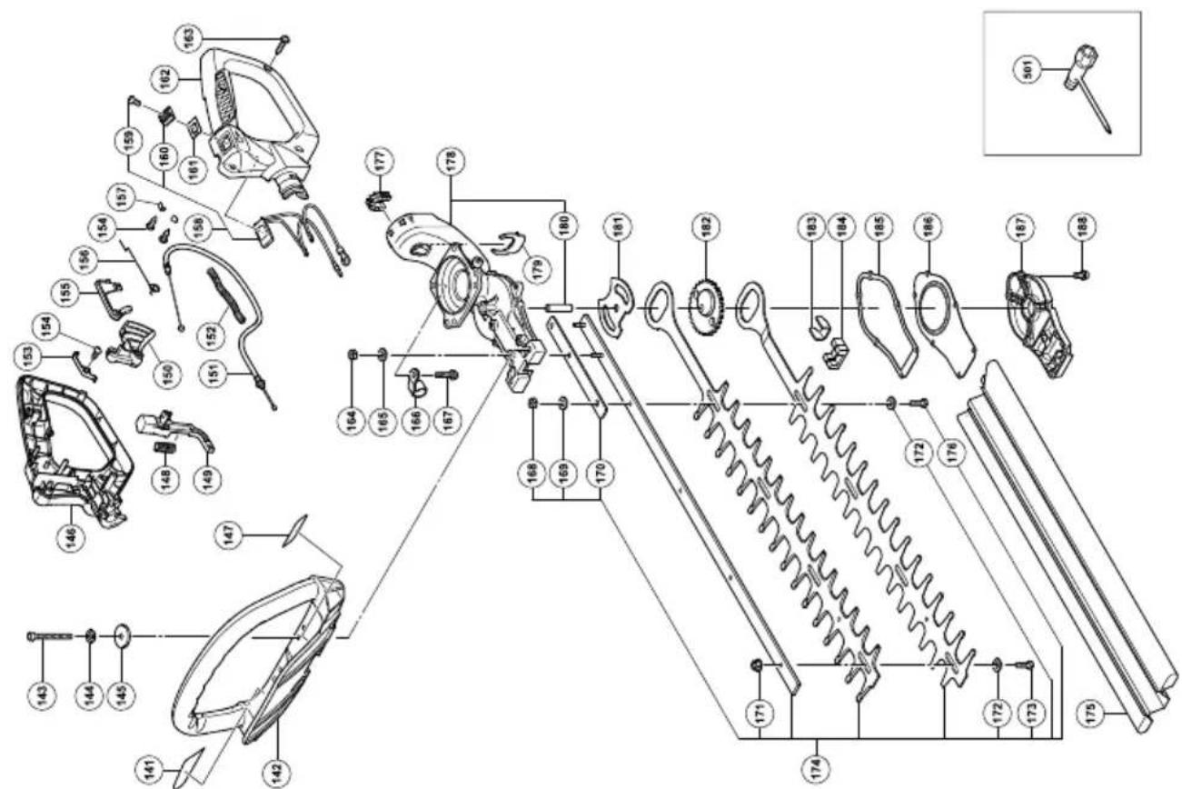
| 141 | NAME PLATE | 1 |
| 142 | HANDLE | 1 |
| 143 | SEAL LOCK HEX. SOCKET HD. BOLT M5×40 | 2 |
| 144 | SPRING WASHER M5 | 2 |
| 145 | BRAKE AXIS WASHER | 2 |
| 146 | HANDLE A | 1 |
| 147 | CAUTION LABEL | 1 |
| 148 | SPRING (A) | 1 |
| 149 | LOCK LEVER | 1 |
| 150 | THROTTLE LEVER | 1 |
| 151 | THROTTLE WIRE | 1 |
| 152 | PROTECTION TUBE | 1 |
| 153 | EARTH TERMINAL | 1 |
| 154 | TAPPING SCREW D3 | 3 |
| 155 | TRIGGER LOCKOUT | 1 |
| 156 | THROTTLE LEVER SPRING | 1 |
| 157 | TAB TERMINAL | 2 |
| 158 | STOP SWITCH ASS'Y (A) | 1 |
| 159 | SCREW M3×10 | 1 |
| 160 | STOP BUTTON(RED) | 1 |
| 161 | STOP BUTTON MARK | 1 |
| 162 | HANDLE B | 1 |
| 163 | TAPPING SCREW (W/FLANGE) D4×16 | 4 |
| 164 | NYLON NUT M5 | 2 |
| 165 | SMALL WASHER 5 | 2 |
| 166 | FIXATION PLATE (B) 1 | |
| 167 | HEX. SOCKET HD. BOLT (W/FLANGE) M6×22 | 1 |
| 168 | NYLON NUT M6 | 1 |
| 169 | BOLT WASHER M6 | 1 |
| 170 | SUPPORT PLATE | 1 |
| 171 | U-NUT M6 | 3 |
| 172 | WASHER D7 | 4 |
| 173 | BOLT (B) | 3 |
| 174 | BLADE ASS'Y (A) | 1 |
| 175 | BLADE CASE (A) | 1 |
| 176 | BOLT (A) | 1 |
| 177 | FLEXIBLE GROMMET | 1 |
| 178 | GEAR CASE (A) ASS'Y | 1 |
| 179 | CLIP | 1 |
| 180 | GEAR SHAFT | 1 |
| 181 | GUIDE PLATE | 1 |
| 182 | GEAR 2 | 1 |
| 183 | HOLDING PLATE | 1 |
| 184 | GREASE STOP A | 2 |
| 185 | GEAR CASE GASKET | 1 |
| 186 | GEAR CASE COVER | 1 |
| 187 | GEAR CASE B | 1 |
| 188 | HEX. SOCKET HD. BOLT (W/WASHERS) M4×18 | 6 |
| 501 | BOX WRENCH 10/19MM | 1 |
CH22EBP

CH22EBP
| Item No. | Part Name Q'TY | |
| 1 | COVER FIXING BOLT COMP | 1 |
| 2 | C L E A N E R | C |
| 3 | C L E A N E R | S |
| 4 | C H O K E V A | L |
| 5 | MACHINE SCREW (W/SP. WASHERS) M5×60 | 2 |
| 6 | C L E A N E R | B |
| 7 | C H O K E H A | N |
| 8 | TAPPING SCREW (W/FLANGE) D4×12 | 1 |
| 9 | S C R E W ( T | A |
| 10 S | CREW (B) 3 | |
| 11 S | CREW (D) 4 | |
| 12 S | YRINGE | 1 |
| 13 P | RIMER BASE | 1 |
| 14 P | JMP GASKET | 1 |
| 15 P | JMP DIAPHRAGM | 1 |
| 16 S | TRAINER | 1 |
| 17 G | UIDE PIN ROLLER 1 | |
| 18 | SYRINGE RETAINER | 1 |
| 19 S | CREW (E) | 1 |
| 20 | BALL PLUG RETAINER | 1 |
| 21 | SCREW (MAIN MIXTURE) | 1 |
| 22 | METERING LEVER SPRING | 1 |
| 23 | PIN | 1 |
| 24 | METERING DIAPHRAGM | 1 |
| 25 | METERING COVER | 1 |
| 26 | SCREW (C) | 2 |
| 27 | POST | 1 |
| 28 | ROTOR COVER | 1 |
| 29 | SCREW (C) | 1 |
| 30 | RETAINING RING (E-TYPE) D2.3 | 1 |
| 31 | O-RING | 1 |
| 32 | INLET NEEDLE VALVE | 1 |
| 33 | SCREW (A) | 1 |
| 34 | METERING LEVER | 1 |
| 35 | METERING GASKET | 1 |
| 36 | CARBURETOR ASS'Y | 1 |
| 37 | CARBURETOR INSULATOR | 1 |
| 38 | INTAKE PACKING | 1 |
| 39 | GLASS WASHER 4 | |
| 40 | CARBURETOR PACKING | 1 |
| 41 | SEAL LOCK HEX. SOCKET BOLT (W/WASHERS) M5×25 | 2 |
| 42 | HEX. SOCKET HD. BOLT (W/WASHERS) M4×18 | 2 |
| 43 | CORD | 1 |
| 44 | CAUTION LABEL | 1 |
| 45 | SEAL LOCK HEX. SOCKET BOLT (W/WASHERS) M4×12 | 1 |
| 46 | CYLINDER COVER | 1 |
| 47 | METAL FITTING OF PLAG CAP (60) | 1 |
| 48 | PLAG CAP | 1 |
| 49 | CORD INSULATION TUBE | 1 |
| 50 | BAND | 1 |
| 51 | IGNITION COIL ASS'Y | 1 |
| 52 | SPARK PLUG | 1 |
| 53 | CYLINDER | 1 |
| 54 | COVER PACKING | 2 |
| 55 | INTAKE COVER (A) | 1 |
| 56 | SEAL LOCK SCREW M4 ×10 | 4 |
| 57 | HEAT PROTECTION PANEL | 1 |
| 58 | MUFFLER ASS'Y | 1 |
| Item No. | Part Name Q'TY | |
| 59 | BOLT WASHER M6 | 2 |
| 60V | HEX. SOCKET HD. BOLT M6×55 | 2 |
| 61O | INTAKECOVER (B) | 1 |
| 62E | PISTON PIN | 1 |
| 63 | PISTON | 1 |
| 64D | HEX. SOCKET HD. BOLT(W/SP.WASHER) M5×18 | 8 |
| 65 L | CYLINDER PACKING | 1 |
| 66 | PISTON RING (R1-1978-3) | 1 |
| 67 | CIR CLIP | 2 |
| 68 | FLYWHEEL NUT M7 1 | |
| 69 | BOLT WASHER D7 | 1 |
| 70 | STARTER PAWL | 2 |
| 71 | STARTER PAWL SPRING | 2 |
| 72 | MAGNETO ROTOR | 1 |
| 73 | RETAINING RING D4 | 2 |
| 74 | CRANK CASE (B) COMP. | 1 |
| 75 | OIL SEAL | 2 |
| 76 | BALL BEARING 6001C3 | 2 |
| 77 | SHIM T0.2 | 1 |
| 78 | SHIM T0.3 | 1 |
| 79 | CRANK SHAFT | 1 |
| 80 | CRANK CASE (A) ASS'Y | 1 |
| 81 | CRANK CASE PACKING | 1 |
| 82 | KNOCK PIN 4 ×12 | 2 |
| 83 | CLUTCH (B) | 1 |
| 84 | CLUTCH DRUM | 1 |
| 85 | BALL BEARING 6002ZC3 | 2 |
| 86 | RETAINING RING FOR D15SHAFT | 1 |
| 87 | GREASE NIPPLE COMP. | 1 |
| 88 | TAPPING SCREW(W/FLANGE) D5×20 | 1 |
| 89 | MUFFLER PROTECTOR | 1 |
| 90 | MACHINE SCREW(W/SP. WASHERS) M5×16 | 1 |
| 91 | HEX. SOCKET BOLT(W/SP. WASHER) M6×18 | 3 |
| 92 | SEAL LOCK HEX. SOCKETBUTTON BOLT(W/WASHERS) M5×20 | 3 |
| 93 | FIXATION PLATE (A) | 1 |
| 94 | FIXATION PLATE (B) | 1 |
| 95 | TAIL PIPE (A) | 1 |
| 96 | EXHAUST COVER | 1 |
| 97 | HITACHI LABEL | 1 |
| 98 | TAPPING SCREW(W/FLANGE) D4.5×18 | 1 |
| 99 | ROPE STOPPER | 1 |
| 100 | STARTER KNOB | 1 |
| 101 | STARTER ROPE | 1 |
| 102 | SEAL LOCK SOCKET BUTTONBOLT (W/WASHERS) M5×20 | 3 |
| 103 | RECOIL SPRING | 1 |
| 104 | REEL | 1 |
| 105 | DAMPER SPRING | 1 |
| 106 | CAM PLATE | 1 |
| 107 | SET SCREW | 1 |
| 108 | STARTER ASS'Y | 1 |
| 109 | AIR DEFLECTOR | 1 |
| 110 | FUEL TANK CAP ASS'Y 1 | |
| 111 | TANK CAP CHAIN | 1 |
| 112 | FUEL GROMMET | 1 |
| 113 | FUEL PIPE | 1 |
| 114 | FUEL PIPE (PINK) | 1 |
| Item No. | Part Name Q'TY | |
| 115 | RETURN GROMMET | 1 |
| 116 | CLIP | 1 |
| 117 | PUMP FILTER | 1 |
| 118 | ANTI VIB. RUBBER | 4 |
| 119 | TANK | 1 |
| 120 | HEAT PROTECTION PANEL (A) | 2 |
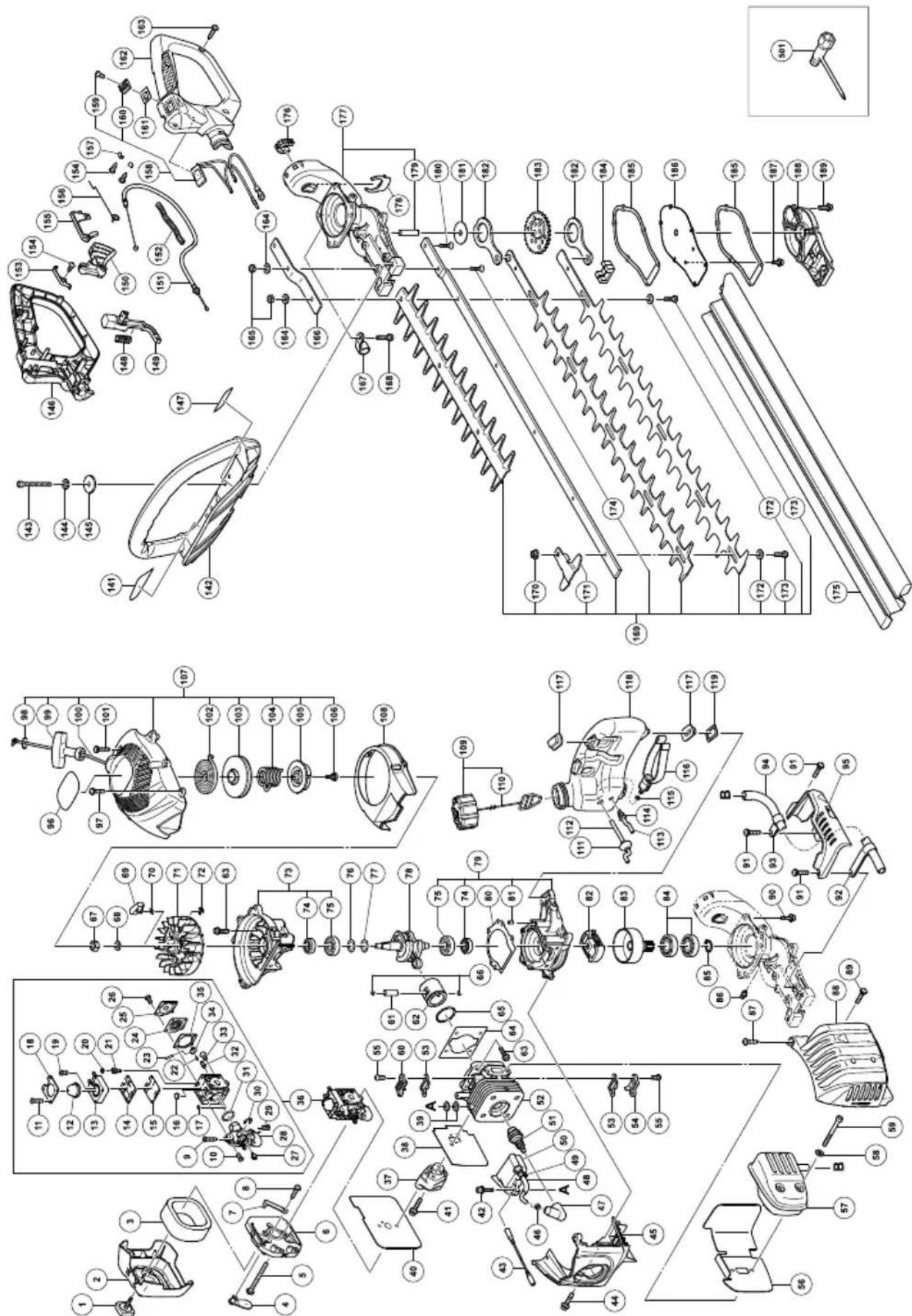
| 141 | NAME PLATE | 1 |
| 142 | HANDLE | 1 |
| 143 | SEASL LOCK HEX. HOLE BOLT 5×40 | 2 |
| 144 | SPRING LOCK WASHER D5 | 2 |
| 145 | BRAKE AXIS WASHER | 2 |
| 146 | HANDLE(A) | 1 |
| 148 | CAUTION LABEL | 1 |
| 149 | SPRING (A) 1 | |
| 150 | LOCK LEVER | 1 |
| 151 | THROTTLE LEVER | 1 |
| 152 | THROTTLE WIRE | 1 |
| 153 | PROTECTION TUBE | 1 |
| 154 | EARTH TERMINAL | 1 |
| 155 | TAPPING SCREW D3 | 3 |
| 156 | TRIGGER LOCKOUT | 1 |
| 157 | THROTTLE LEVER SPRING | 1 |
| 158 | TAB TERMINAL | 2 |
| 159 | STOP SWITCH ASS'Y | 1 |
| 160 | SCREW M3X10 | 1 |
| 161 | STOP BUTTON (RED) | 1 |
| 162 | STOP BUTTON MARK | 1 |
| 163 | HANDLE (B) | 1 |
| 164 | TAPPING SCREW (W/FLANGE) D4×16 | 4 |
| 165 | WASHER 6 | 3 |
| 166 | NYLON NUT M6 | 3 |
| 167 | SUPPORT PLATE | 1 |
| 168 | FIXATION PLATE (B) 1 | |
| 169 | HEX. SOCKET HD. BOLT (W/FLANGE) M6×22 | 1 |
| 170 | BLADE ASS'Y | 1 |
| 171 | U-NUT M6 | 4 |
| 172 | GUARD PLATE | 1 |
| 173 | WASHER D7 | 5 |
| 174 | BOLT (A) | 5 |
| 175 | HEX. SOCKET FLAT HD. SCREW M6×25 | 1 |
| 176 | BLADE CASE | 1 |
| 177 | FLEXIBLE GROMMET | 1 |
| 178 | GEAR CASE (A) ASS'Y | 1 |
| 179 | CLIP | 1 |
| 180 | GEAR AXIS | 1 |
| 181 | HEX. SOCKET FLAT HD. SCREW M6×25 | 1 |
| 182 | GUIDE PLATE | 1 |
| 183 | CAM ROD | 2 |
| 184 | GEAR 2 | 1 |
| 185 | GREASE STOP A 2 | |
| 186 | GEAR CASE GASKET | 2 |
| 187 | GEAR CASE COVER | 1 |
| 188 | HEX. SOCKET HD. BOLT M4×10 | 2 |
| 189 | GEAR CASE B | 1 |
| 190 | HEX. SOCKET HD. BOLT (W/WASHERS) M4×18 | 6 |
| 501 | COMBI. BOX SPANNER 10×19 ,PLUS | 1 |
CH22EB
CH22EB
| Item No. | Part Name Q'TY | |
| 1 | COVER FIXING BOLT COMP | 1 |
| 2 | C L E A N E | R |
| 3 | C L E A N E | R |
| 4 | C H O K E | V A |
| 5 | MACHINE SCREW (W/WASHERS) M5×60 | 2 |
| 6 | C L E A N E | R |
| 7 | C H O K E | H A |
| 8 | TAPPING SCREW (W/FLANGE) D4×12 | 1 |
| 9 | S C R E W | ( T |
| 10 | SCREW (B) 3 | |
| 11 | SCREW (D) 4 | |
| 12 | SYRINGE 1 | |
| 13 | PRIMER BASE ASS'Y 1 | |
| 14 | PUMP GASKET | 1 |
| 15 | PUMP DIAPHRAGM | 1 |
| 16 | STRAINER | 1 |
| 17 | GUIDE PIN ROLLER | 1 |
| 18 | SYRINGE RETAINER | 1 |
| 19 | SCREW (E) | 1 |
| 20 | BALL PLUG RETAINER | 1 |
| 21 | SCREW (MAIN MIXTURE) | 1 |
| 22 | METERING LEVER SPRING | 1 |
| 23 | PIN | 1 |
| 24 | METERING DIAPHRAGM ASS'Y | 1 |
| 25 | METERING COVER | 1 |
| 26 | SCREW (C) | 2 |
| 27 | POST | 1 |
| 28 | ROTOR COVER ASS'Y 1 | |
| 29 | SCREW (C) | 1 |
| 30 | RETAINING RING (E-TYPE) D2.3 | 1 |
| 31 | O-RING | 1 |
| 32 | INLET NEEDLE VALVE 1 | |
| 33 | SCREW (A) | 1 |
| 34 | METERING LEVER | 1 |
| 35 | METERING GASKET 1 | |
| 36 | CARBURETOR ASS'Y | 1 |
| 37 | CARBURETOR INSULATOR | 1 |
| 38 | INTAKE PACKING | 1 |
| 39 | GLASS WASHER | 4 |
| 40 | CARBURETOR PACKING | 1 |
| 41 | SEAL LOCK HEX. SOCKET BOLT (W/WASHERS) M5 | 2 |
| 42 | HEX. SOCKET HD. BOLT (W/WASHERS) M4×18 | 2 |
| 43 | CORD | 1 |
| 44 | SEAL LOCK HEX. SOCKET HD. BOLT M4×12 | 1 |
| 45 | CYLINDER COVER | 1 |
| 46 | METAL FITTING OF PLUG CAP | 1 |
| 47 | PLAG CAP | 1 |
| 48 | CORD INSULATION TUBE | 1 |
| 49 | BAND | 1 |
| 50 | IGNITION COIL | 1 |
| 51 | SPARK PLUG | 1 |
| 52 | CYLINDER | 1 |
| 53 | COVER PACKING | 2 |
| 54 | INTAKE COVER (A) | 1 |
| 55 | SEAL LOCK SCREW M4×10 | 4 |
| 56 | HEAT PROTECTION PANEL | 1 |
| 57 | MUFFLER ASS'Y | 1 |
| Item No. | Part Name Q'TY | |
| 58 | BOLT WASHER M6 2 | |
| C9S | CHEX. SOCKET HD. BOLTM6×55 N G E 1 | 2 |
| 60 | INTAKE COVER (B) | 1 |
| 61 | PISTON PIN | 1 |
| 62 | PISTON | 1 |
| B3N | CHEX. SOCKET HD. BOLT(W/SP.WASHER)M5×18 | 8 |
| 64 | CYLINDER PACKING 1 | |
| 65 | PISTON RING | 1 |
| A6 | PISTON PIN CIR CLIP | 2 |
| 67 | FLYWHEEL NUT | 1 |
| 68 | BOLT WASHER D7 1 | |
| 69 | STARTER PAWL | 2 |
| 70 | STARTER PAWL SPRING | 2 |
| 71 | MAGNETO ROTOR | 1 |
| 72 | RETAINING RING D4 | 2 |
| 73 | CRANK CASE (B) COMP. | 1 |
| 74 | OIL SEAL TB 12227 | 2 |
| 75 | BALL BEARING 6001C3 | 2 |
| 76 | SHIM T0.2 | 1 |
| 77 | SHIM T0.3 | 1 |
| 78 | CRANK SHAFT | 1 |
| 79 | CRANK CASE (A) ASS'Y 1 | |
| 80 | CRANK CASE PACKING 1 | |
| 81 | KNOCK PIN 4 ×12 | 2 |
| 82 | CLUTCH (B) | 1 |
| 83 | CLUTCH DRUM | 1 |
| 84 | BALL BEARING 6002ZC3 | 2 |
| 85 | RETAINING RING FOR D15 SHAFT | 1 |
| 86 | GREASE NIPPLE COMP. | 1 |
| 87 | TAPPING SCREW(W/FLANGE) D5×20 | 1 |
| 88 | MUFFLER PROTECTOR | 1 |
| 89 | MACHINE SCREW(W/WASHERS) M5×16 | 1 |
| 90 | HEX. HOLE BOLT 6 ×18/S | 3 |
| 91 | HEX. SOCKET HD. BOLT(W/BUTTON) M5×20 | 3 |
| 92 | FIXATION PLATE (A) | 1 |
| 93 | FIXATION PLATE (B) | 1 |
| 94 | TAIL PIPE (A) | 1 |
| 95 | EXHAUST COVER | 1 |
| 96 | HITACHI LABEL | 1 |
| 97 | TAPPING SCREW(W/FLANGE) D4×16 | 5 |
| 98 | PLATE | 1 |
| 99 | STARTER KNOB | 1 |
| 100 | STARTER ROPE | 1 |
| 101 | HEX. SOCKET HD. BOLT(W/BUTTON) M5×20 | 3 |
| 102 | RECOIL SPRING | 1 |
| 103 | STARTER ROPE REEL 1 | |
| 104 | DAMPER SPRING | 1 |
| 105 | CAM PLATE | 1 |
| 106 | SET SCREW | 1 |
| 107 | RECOIL STARTER | 1 |
| 108 | AIR DEFLECTOR | 1 |
| 109 | FUEL TANK CAP ASS'Y | 1 |
| 110 | TANK CAP CHAIN | 1 |
| 111 | FUEL GROMMET | 1 |
| 112 | FUEL PIPE | 1 |
| 113 | FUEL PIPE (PINK) | 1 |
| 114 | RETURN GROMMET | 1 |
| Item No. | Part Name Q'TY | |
| 115 | CLIP | 1 |
| 116 | PUMP FILTER | 1 |
| 117 | CUSHION RUBBER | 4 |
| 118 | TANK | 1 |
| 119 | HEAT PROTECTION PANEL (A) | 2 |
| 141 | NAME PLATE | 1 |
| 142 | HANDLE | 1 |
| 143 | SEAL LOCK HEX. SOCKET HD. BOLT M5×40 | 2 |
| 144 | SPRING LOCK WASHER D5 | 2 |
| 145 | BRAKE AXIS WASHER | 2 |
| 146 | HANDLE(A) | 1 |
| 147 | CAUTION LABEL | 1 |
| 148 | SPRING (A) | 1 |
| 149 | LOCK LEVER | 1 |
| 150 | THROTTLE LEVER 1 | |
| 151 | THROTTLE WIRE | 1 |
| 152 | PROTECTION TUBE | 1 |
| 153 | EARTH TERMINAL 1 | |
| 154 | TAPPING SCREW D3 3 | |
| 155 | TRIGGER LOCKOUT | 1 |
| 156 | THROTTLE LEVER SPRING | 1 |
| 157 | TAB TERMINAL | 2 |
| 158 | STOP SWITCH (A) ASS'Y | 1 |
| 159 | SCREW M3 ×10 | 1 |
| 160 | STOP BUTTON (RED) | 1 |
| 161 | STOP BUTTON MARK | 1 |
| 162 | HANDLE (B) | 1 |
| 163 | TAPPING SCREW (W/FLANGE) D4×16 | 4 |
| 164 | WASHER 6 | 3 |
| 165 | NYLON NUT M6 | 3 |
| 166 | SUPPORT PLATE | 1 |
| 167 | FIXATION PLATE (B) | 1 |
| 168 | HEX. SOCKET HD. BOLT (W/FLANGE) M6×22 | 1 |
| 169 | BLADE ASS'Y | 1 |
| 170 | U-NUT M6 | 4 |
| 171 | GUARD PLATE | 1 |
| 172 | WASHER D7 | 5 |
| 173 | BOLT (A) | 5 |
| 174 | HEX. SOCKET FLAT HD. SCREW M6×25 | 1 |
| 175 | BLADE CASE | 1 |
| 176 | FLEXIBLE GROMMET | 1 |
| 177 | GEAR CASE (A) ASS'Y 1 | |
| 178 | CLIP | 1 |
| 179 | GEAR AXIS | 1 |
| 180 | HEX. SOCKET FLAT HD. SCREW M6×25 | 1 |
| 181 | GUIDE PLATE | 1 |
| 182 | CAM ROD | 2 |
| 183 | GEAR 2 | 1 |
| 184 | GREASE STOP A | 2 |
| 185 | GEAR CASE GASKET | 2 |
| 186 | GEAR CASE COVER | 1 |
| 187 | HEX. SOCKET HD. BOLT M4×10 | 2 |
| 188 | GEAR CASE B | 1 |
| 189 | HEX. SOCKET HD. BOLT (W/WASHERS) M4×18 | 6 |
| 501 | BOX WRENCH 10/19MM | 1 |
CH22ECP
CH22ECP
| Item No. | Part Name Q'TY | |
| 1 COVER FIXING BOLT COMP 1 | ||
| 2 | C L E A N E R | C |
| 3 | C L E A N E R | S |
| 4 | C H O K E V | A L |
| 5 | MACHINE SCREW (W/WASHERS) M5×60 | 2 |
| 6 | C L E A N E R | B |
| 7 | C H O K E H | A N |
| 8 | TAPPING SCREW (W/FLANGE) D4×12 | 1 |
| 9 | S C R E W ( | T A |
| 10 SCREW (B) 3 | ||
| 11 SCREW (D) 4 | ||
| 12 SYRINGE | 1 | |
| 13 PRIMER BASE ASS'Y 1 | ||
| 14 PUMP GASKET | 1 | |
| 15 | PUMP DIAPHRAGM | 1 |
| 16 STRAINER | 1 | |
| 17 | GUIDE PIN ROLLER | 1 |
| 18 | SYRINGE RETAINER | 1 |
| 19 SCREW (E) 1 | ||
| 20 | BALL PLUG RETAINER | 1 |
| 21 | SCREW (MAIN MIXTURE) | 1 |
| 22 | METERING LEVER SPRING | 1 |
| 23 | PIN | 1 |
| 24 | METERING DIAPHRAGM ASS'Y | 1 |
| 25 | METERING COVER | 1 |
| 26 | SCREW (C) | 2 |
| 27 | POST | 1 |
| 28 | ROTOR COVER ASS'Y | 1 |
| 29 | SCREW (C) | 1 |
| 30 | RETAINING RING (E-TYPE) D2.3 | 1 |
| 31 | O-RING | 1 |
| 32 | INLET NEEDLE VALVE | 1 |
| 33 | SCREW (A) | 1 |
| 34 | METERING LEVER | 1 |
| 35 | METERING GASKET | 1 |
| 36 | CARBURETOR ASS'Y | 1 |
| 37 | CARBURETOR INSULATOR | 1 |
| 38 | INTAKE PACKING 1 | |
| 39 | GLASS WASHER | 4 |
| 40 | CARBURETOR PACKING | 1 |
| 41 | SEAL LOCK HEX. SOCKET BOLT (W/WASHERS)M5 | 2 |
| 42 | HEX. SOCKET HD. BOLT (W/WASHERS) M4×18 | 2 |
| 43 | CORD | 1 |
| 44 | CAUTION LABEL | 1 |
| 45 | SEAL LOCK HEX. SOCKET HD. BOLT M4×12 | 1 |
| 46 | CYLINDER COVER | 1 |
| 47 | METAL FITTING OF PLUG CAP | 1 |
| 48 | PLAG CAP | 1 |
| 49 | CORD INSULATION TUBE | 1 |
| 50 | BAND | 1 |
| 51 IGNITION COIL | 1 | |
| 52 | SPARK PLUG | 1 |
| 53 | CYLINDER | 1 |
| 54 | COVER PACKING 2 | |
| 55 | INTAKE COVER (A) | 1 |
| 56 | SEAL LOCK SCREW M4×10 | 4 |
| 57 | HEAT PROTECTION PANEL | 1 |
| 58 | MUFFLER ASS'Y | 1 |
| 59 | BOLT WASHER M6 | 2 |
| 60 | HEX. SOCKET HD. BOLT M6×55 | 2 |
| Item No. | Part Name Q'TY | |
| 61 | INTAKE COVER (B) | 1 |
| O 62 V | PISETON PIN 1 | 1 |
| P 63 O | PISTONG E 1 | 1 |
| V 64 E | HEX. SOCKET HD. BOLT(W/SP.WASHER) M5×18 | 8 |
| 65 | CYLINDER PACKING | 1 |
| O 66 D | PISTON RING | 1 |
| D67 L | PISETON PIN CIR CLIP | 2 |
| 68 | FLYWHEEL NUT | 1 |
| 69 | BOLT WASHER D7 1 | |
| S 70 ) | STARTER PAWL | 2 |
| 71 | STARTER PAWL SPRING | 2 |
| 72 | MAGNETO ROTOR | 1 |
| 73 | RETAINING RING D4 | 2 |
| 74 CRANK CASE (B) ASS'Y | 1 | |
| 75 | OIL SEAL TB 12227 | 2 |
| 76 | BALL BEARING 6001C3 2 | |
| 77 | SHIM T0.2 | 1 |
| 78 | SHIM T0.3 | 1 |
| 79 | CRANK SHAFT | 1 |
| 80 | CRANK CASE (A) ASS'Y | 1 |
| 81 | CRANK CASE PACKING | 1 |
| 82 | KNOCK PIN 4×12 | 2 |
| 83 | CLUTCH (B) | 1 |
| 84 | CLUTCH DRUM COMP. | 1 |
| 85 | BALL BEARING 6002ZC3 | 2 |
| 86 | RETAINING RING FOR D15 SHAFT | 1 |
| 87 | GREASE NIPPLE COMP. | 1 |
| 88 | TAPPING SCREW (W/FLANGE)D5×20 | 2 |
| 89 | MUFFLER PROTECTOR | 1 |
| 90 | SCREW (W/WASHERS) M5×16 | 1 |
| 91 | TAIL PIPE | 1 |
| 92 | FIXATION PLATE (A) 1 | |
| 93 | MACHINE SCREW(W/WASHERS) M4×10 | 1 |
| 94 | FIXATION PLATE (B) 1 | |
| 95 | HEX. SOCKET HD. BOLT(W/FLANGE) M6×22 | 1 |
| 96 | HEX. HOLE BOLT 6×18/S | 3 |
| 97 | HITACHI LABEL | 1 |
| 98 | TAPPING SCREW D4.5×16 | 1 |
| 99 | PLATE | 1 |
| 100 | STARTER KNOB | 1 |
| 101 | STARTER ROPE | 1 |
| 102 | HEX. SOCKET HD. BOLT(W/BUTTON) M5×20 | 3 |
| 103 | RECOIL SPRING | 1 |
| 104 | STARTER ROPE REEL | 1 |
| 105 | DAMPER SPRING | 1 |
| 106 | CAM PLATE | 1 |
| 107 | SET SCREW | 1 |
| 108 | RECOIL STARTER | 1 |
| 109 | AIR DEFLECTOR | 1 |
| 110 | FUEL TANK CAP ASS'Y | 1 |
| 111 | TANK CAP CHAIN | 1 |
| 112 | FUEL GROMMET | 1 |
| 113 | FUEL PIPE | 1 |
| 114 | FUEL PIPE (PINK) 1 | |
| 115 | RETURN GROMMET | 1 |
| 116 | CLIP | 1 |
| 117 | PUMP FILTER | 1 |
| 118 | CUSHION RUBBER | 4 |
| 119 | TANK | 1 |
| 120 | HEAT PROTECTION PANEL (A) | 2 |
| Item No. | Part Name Q'TY | |
| 141 | HEX. SOCKET HD. BOLT (W/FLANGE) M6×32 | 2 |
| 142 | FRONT HANDLE | 1 |
| 143 | CAUTION LABEL | 1 |
| 144 | FRAME | 1 |
| 145 | NAME PLATE | 1 |
| 147 | DAMPER | 1 |
| 148 | TAPPING SCREW (W/FLANGE) D5×20 | 1 |
| 149 | HANDLE (A) | 1 |
| 150 | SPRING (A) | 1 |
| 151 | LOCK LEVER | 1 |
| 152 | THROTTLE LEVER | 1 |
| 153 | THROTTLE WIRE | 1 |
| 154 | PROTECTION TUBE | 1 |
| 155 | PROTECTION TUBE | 1 |
| 156 | BAND | 1 |
| 157 | EARTH TERMINAL | 1 |
| 158 | TAPPING SCREW D3 3 | |
| 159 | TRIGGER LOCKOUT | 1 |
| 160 | THROTTLE LEVER SPRING | 1 |
| 161 | TAB TERMINAL | 2 |
| 162 | STOP SWITCH (A) | 1 |
| 163 | SCREW M3×10 | 1 |
| 164 | STOP BUTTON (RED) | 1 |
| 165 | STOP BUTTON MARK 1 | |
| 166 | HANDLE B | 1 |
| 167 | TAPPING SCREW (W/FLANGE) D4×16 | 4 |
| 168 | HEX. SOCKET HD. BOLT (W/FLANGE) M6×20 | 2 |
| 169 | CLIP | 1 |
| 170 | NYLON NUT M6 | 3 |
| 171 | WASHER 6 | 3 |
| 172 | SUPPORT PLATE | 1 |
| 173 | SPRING HOLDER 4 | |
| 174 | HEX. SOCKET HD. BOLT (W/FLANGE) M5×10 | 4 |
| 175 | ANTIVIBRATION SPRING | 4 |
| 176 | BLADE ASS'Y | 1 |
| 177 | U-NUT M6 | 4(5) |
| 178 | GUARD PLATE | 1 |
| 179 | WASHER M7 | 5(6) |
| 180 | BOLT (A) | 5(6) |
| 181 | HEX. SOCKET FLAT HD. SCREW M6×25 | 1 |
| 182 | WIRE | 1 |
| 183 | MACHINE SCREW (W/WASHERS) M5×10 | 1 |
| 184 | GEAR CASE ASS'Y | 1 |
| 185 | NEEDLE BEARING HK0810B | 1 |
| 186 | HEX. SOCKET FLAT HD. SCREW M6×25 | 1 |
| 187 | GUIDE PLATE | 1 |
| 188 | CAM ROD | 2 |
| 189 | GEAR 2 COMP. | 1 |
| 190 | GREASE STOP A | 2 |
| 191 | GEAR CASE GASKET | 2 |
| 192 | GEAR CASE COVER 1 | |
| 193 | BALL BEARING 608ZZC3 | 1 |
| 194 | GEAR CASE B COMP. | 1 |
| 195 | HEX. SOCKET HD. BOLT (W/WASHERS) M4×18 | 6 |
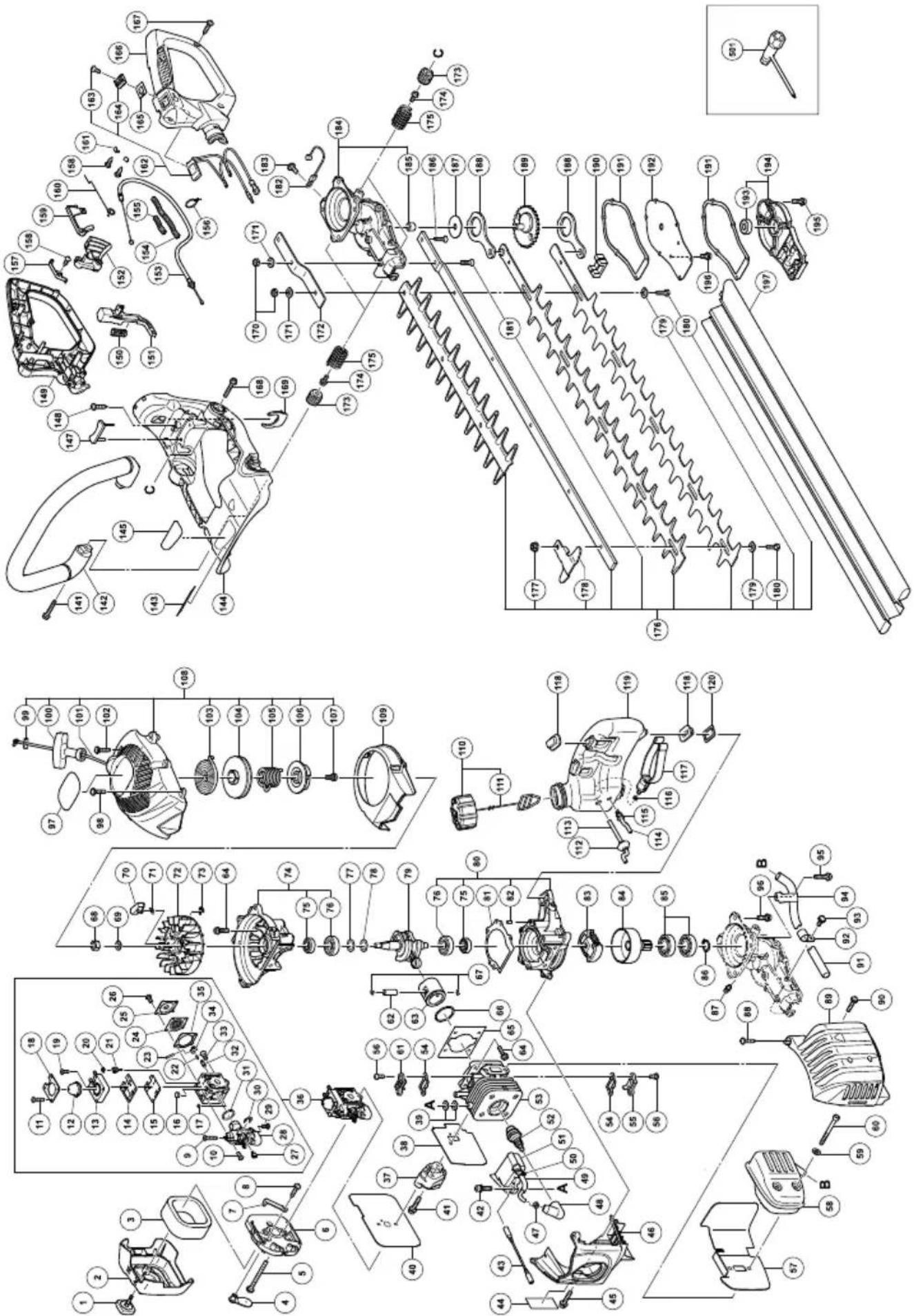
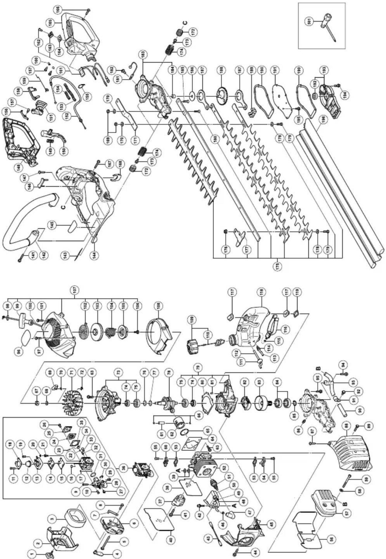
| 196 | HEX. SOCKET HD. BOLT M4×10 | 2 |
| 197 | BLADE CASE | 1 |
| 501 | BOX WRENCH 10/19MM | 1 |
CH22EC
CH22EC
| Item No. | Part Name Q'TY | |
| 1 COVER FIXING BOLT COMP 1 | ||
| 2 | C L E A N E R | C |
| 3 | C L E A N E R | S |
| 4 | C H O K E V A | L |
| 5 | MACHINE SCREW (W/WASHERS) M5×60 | 2 |
| 6 | C L E A N E R | B |
| 7 | C H O K E H A | N |
| 8 | TAPPING SCREW (W/FLANGE) D4×12 | 1 |
| 9 | S C R E W ( T | A |
| 10 SCREW (B) 3 | ||
| 11 SCREW (D) 4 | ||
| 12 SYRINGE | ||
| 13 PRIMER BASE ASS'Y | ||
| 14 PUMP GASKET | ||
| 15 PUMP DIAPHRAGM | ||
| 16 STRAINER | ||
| 17 | GUIDE PIN ROLLER | 1 |
| 18 | SYRINGE RETAINER | 1 |
| 19 SCREW (E) 1 | ||
| 20 | BALL PLUG RETAINER | 1 |
| 21 | SCREW (MAIN MIXTURE) | 1 |
| 22 | METERING LEVER SPRING | 1 |
| 23 | PIN | 1 |
| 24 | METERING DIAPHRAGM ASS'Y | 1 |
| 25 | METERING COVER | 1 |
| 26 | SCREW (C) | 2 |
| 27 | POST | 1 |
| 28 | ROTOR COVER ASS'Y | 1 |
| 29 | SCREW (C) | 1 |
| 30 | RETAINING RING (E-TYPE) D2.3 | 1 |
| 31 | O-RING | 1 |
| 32 | INLET NEEDLE VALVE | 1 |
| 33 | SCREW (A) | 1 |
| 34 | METERING LEVER | 1 |
| 35 | METERING GASKET | 1 |
| 36 | CARBURETOR ASS'Y | 1 |
| 37 | CARBURETOR INSULATOR | 1 |
| 38 | INTAKE PACKING | 1 |
| 39 | GLASS WASHER | 4 |
| 40 | CARBURETOR PACKING | 1 |
| 41 | SEAL LOCK HEX. SOCKET BOLT (W/WASHERS)M5 | 2 |
| 42 | HEX. SOCKET HD. BOLT (W/WASHERS) M4×18 | 2 |
| 43 | CORD | 1 |
| 44 | SEAL LOCK HEX. SOCKET HD. BOLT M4×12 | 1 |
| 45 | CYLINDER COVER | 1 |
| 46 | METAL FITTING OF PLUG CAP | 1 |
| 47 PLAG CAP | ||
| 48 | CORD INSULATION TUBE | 1 |
| 49 | BAND | 1 |
| 50 | IGNITION COIL | 1 |
| 51 | SPARK PLUG | 1 |
| 52 | CYLINDER | 1 |
| 53 | COVER PACKING 2 | |
| 54 | INTAKE COVER (A) | 1 |
| 55 | SEAL LOCK SCREW M4×10 | 4 |
| 56 | HEAT PROTECTION PANEL | 1 |
| 57 | MUFFLER ASS'Y | 1 |
| 58 | BOLT WASHER M6 | 2 |
| 59 | HEX. SOCKET HD. BOLT M6×55 | 2 |
| 60 | INTAKE COVER (B) | 1 |
| Item No. | Part Name Q'TY | |
| 61 | PISTON PIN | 1 |
| O 62 V | PISETONR 1 | 1 |
| P 63 O V E | HEM. SOCKETED. BOLT (W/SP.WASHER) M5×18 | 8 |
| 64 | CYLINDER PACKING | 1 |
| 65 | PISTON RING | 1 |
| O 66 D | PISTON PIN CIR CLIP | 2 |
| D67 L | FLYWHEEL NUT | 1 |
| 68 | BOLT WASHER D7 1 | |
| 69 | STARTER PAWL | 2 |
| S 70) | STARTER PAWL SPRING | 2 |
| 71 | MAGNETO ROTOR | 1 |
| 72 | RETAINING RING D4 | 2 |
| 73 | CRANK CASE (B) ASS'Y | 1 |
| 74 | OIL SEAL TB 12227 | 2 |
| 75 | BALL BEARING 6001C3 2 | |
| 76 | SHIM T0.2 | 1 |
| 77 | SHIM T0.3 | 1 |
| 78 | CRANK SHAFT | 1 |
| 79 | CRANK CASE (A) ASS'Y | 1 |
| 80 | CRANK CASE PACKING | 1 |
| 81 | KNOCK PIN 4×12 | 2 |
| 82 | CLUTCH (B) | 1 |
| 83 | CLUTCH DRUM COMP. | 1 |
| 84 | BALL BEARING 6002ZC3 | 2 |
| 85 | RETAINING RING FOR D15 SHAFT | 1 |
| 86 | GREASE NIPPLE COMP. | 1 |
| 87 | TAPPING SCREW (W/FLANGE) D5×20 | 2 |
| 88 | MUFFLER PROTECTOR | 1 |
| 89 | SCREW (W/WASHERS) M5×16 | 1 |
| 90 | TAIL PIPE | 1 |
| 91 | FIXATION PLATE (A) 1 | |
| 92 | MACHINE SCREW (W/WASHERS) M4×10 | 1 |
| 93 | FIXATION PLATE (B) 1 | |
| 94 | HEX. SOCKET HD. BOLT (W/FLANGE) M6×22 | 1 |
| 95 | HEX. HOLE BOLT 6×18/S | 3 |
| 96 | HITACHI LABEL | 1 |
| 97 | TAPPING SCREW D4.5×16 | 1 |
| 98 | PLATE | 1 |
| 99 | STARTER KNOB | 1 |
| 100 | STARTER ROPE | 1 |
| 101 | HEX. SOCKET HD. BOLT (W/BUTTON) M5×20 | 3 |
| 102 | RECOIL SPRING | 1 |
| 103 | STARTER ROPE REEL | 1 |
| 104 | DAMPER SPRING | 1 |
| 105 | CAM PLATE | 1 |
| 106 | SET SCREW | 1 |
| 107 | RECOIL STARTER | 1 |
| 108 | AIR DEFLECTOR | 1 |
| 109 | FUEL TANK CAP ASS'Y | 1 |
| 110 | TANK CAP CHAIN | 1 |
| 111 | FUEL GROMMET | 1 |
| 112 | FUEL PIPE | 1 |
| 113 | FUEL PIPE (PINK) | 1 |
| 114 | RETURN GROMMET | 1 |
| 115 | CLIP | 1 |
| 116 | PUMP FILTER | 1 |
| 117 | CUSHION RUBBER | 4 |
| 118 | TANK | 1 |
| 119 | HEAT PROTECTION PANEL (A) | 2 |
| Item No. | Part Name Q'TY | |
| 141 | HEX. SOCKET HD. BOLT (W/FLANGE) M6×32 | 2 |
| 142 | FRONT HANDLE | 1 |
| 143 | CAUTION LABEL | 1 |
| 144 | FRAME | 1 |
| 145 | NAME PLATE | 1 |
| 146 | DAMPER | 1 |
| 147 | TAPPING SCREW (W/FLANGE) D5×20 | 1 |
| 148 | HANDLE (A) | 1 |
| 149 | SPRING (A) | 1 |
| 151 | THROTTLE LEVER | 1 |
| 150 | LOCK LEVER | 1 |
| 152 | THROTTLE WIRE | 1 |
| 153 | PROTECTION TUBE 1 | |
| 154 | PROTECTION TUBE (L50) | 1 |
| 155 | BAND | 1 |
| 156 | EARTH TERMINAL | 1 |
| 157 | TAPPING SCREW D3 | 3 |
| 158 | TRIGGER LOCKOUT | 1 |
| 159 | THROTTLE LEVER SPRING | 1 |
| 160 | TAB TERMINAL | 2 |
| 161 | STOP SWITCH (A) | 1 |
| 162 | SCREW M3X10 | 1 |
| 163 | STOP BUTTON (RED) | 1 |
| 164 | STOP BUTTON MARK 1 | |
| 165 | HANDLE B | 1 |
| 166 | TAPPING SCREW (W/FLANGE) D4×16 | 4 |
| 167 | HEX. SOCKET HD. BOLT (W/FLANGE) M6×22 | 2 |
| 168 | CLIP | 1 |
| 169 | NYLON NUT M6 | 3 |
| 170 | WASHER 6 | 3 |
| 171 | SUPPORT PLATE | 1 |
| 172 | SPRING HOLDER 4 | |
| 173 | HEX. SOCKET HD. BOLT (W/FLANGE) M5×10 | 4 |
| 174 | ANTIVIBRATION SPRING | 4 |
| 175 | BLADE ASS'Y | 1 |
| 176 | U-NUT M6 | 4(5) |
| 177 | GUARD PLATE | 1 |
| 178 | WASHER M7 | 5(6) |
| 179 | BOLT (A) | 5(6) |
| 180 | HEX. SOCKET FLAT HD. SCREW M6×25 | 1 |
| 181 | WIRE | 1 |
| 182 | MACHINE SCREW (W/WASHERS) M5×10 | 1 |
| 183 | GEAR CASE ASS'Y | 1 |
| 184 | NEEDLE BEARING HK0810B | 1 |
| 185 | HEX. SOCKET FLAT HD. SCREW M6×25 | 1 |
| 186 | GUIDE PLATE | 1 |
| 187 | CAM ROD | 2 |
| 188 | GEAR 2 COMP. | 1 |
| 189 | GREASE STOP A | 2 |
| 190 | GEAR CASE GASKET | 2 |
| 191 | GEAR CASE COVER | 1 |
| 192 | BALL BEARING 608ZZC3 | 1 |
| 193 | GEAR CASE B COMP. | 1 |
| 194 | HEX. SOCKET HD. BOLT (W/WASHERS) M4×18 | 6 |
| 195 | HEX. SOCKET HD. BOLT M4×10 | 2 |
| 196 | BLADE CASE | 1 |
| 501 | BOX WRENCH 10/19MM | 1 |
| English EC DECLARATION OF CONFORMITY Português DECLARA(Applies to Europe only)We declare under our sole responsibility that this product is in conformity with Directive 2006/42/EC, 2004/108/EC and 2000/14/EC. The following standards have been taken into consideration.ISO 3767/3864, ISO 10517(EN 774) (EN ISO 12100-1/2)Annex V (2000/14/EC): For information relating to noise emissions, see the chapter specifications.The European Standards Manager at Hitachi Koki Europe Ltd. is authorized to compile the technical fi ie.This declaration is applicable to the product affi xed CE marking. | AÇÃO DE CONFORMIDADE CE(Aplica-se apenas à Europa)Declaramos para os devidos efeitos que este produto cumpre os requisitos das directivas comunitárias 2006/42/CE, 2004/108/CE e 2000/14/CE. As seguintes normas harmonizadas foram aplicadas.ISO 3767/3864, ISO 10517(EN 774) (EN ISO 12100-1/2)Anexo V (2000/14/CE): Para obter mais informações relacionadas com emissões de ruído, consulte as especificações do capítulo.O Gestor de Normas Europeias da Hitachi Koki Europe Ltd. está autorizado a compilar o ficheiro técnico.Esta declaração se aplica aos produtos designados CE. | |||
| Deutsch EG-KONFORMITÄTSERKLÄRUNG(Gilt nur für Europa)Wir erklären eigenverantwortlich, dass dieses Produkt den Bestimmungen der Richtlinien 2006/42/EG, 2004/108/EG und 2000/14/EG des Europäischen Rates entspricht. Die nachfolgenden Standards wurden in Betracht gezogen.ISO 3767/3864, ISO 10517(EN 774) (EN ISO 12100-1/2)Anhang V (2000/14/EG): Informationen zur Geräuschentwicklung finden Sie im Kapitel Spezifi zierungen.Der Manager für europäische Standards bei der Hitachi Koki Europe Ltd. ist zum Verfassen der technischen Datei befugt.Diese Erklärung gilt für Produkte, die die CE-Markierung tragen. | Svenska | EF-DEKLARATION BETRÄFFANDE LIKFORMIGHET(Gäller endast Europa)Vi intygar under ensamt ansvar, att denna produkt motsvarar bestämmelserna i direktiven 2006/42/EF, 2004/108/EF och 2000/14/EF.Vi har tagit hänsyn till följande standards.ISO 3767/3864, ISO 10517(EN 774) (EN ISO 12100-1/2)Bilaga V (2000/14/EF): För information rörande buller, se kapitelbeskrivningen.Den europeiska standardansvarige på Hitachi Koki Europe Ltd. är auktoriserad att utarbeta den tekniska fi len.Denna deklaration gäller för CE-märkningen på produkten. | ||
| Français | DECLARATION DE CONFORMITE CE(Concerne l'Europe uniquement)Nous déclarons sur la foi de notre seule responsabilité que ce produit est conforme aux dispositions des Directives du Conseil de l'Union européenne 2006/42/EC, 2004/108/EC et 2000/14/EC. Les nonnes suivantes ont été prises en considération.ISO 3767/3864, ISO 10517(EN 774) (EN ISO 12100-1/2)Annexe V (2000/14/EC): Pour les informations relatives aux émissions de bruits, reportez-vous au chapitre Caractéristiques.Le responsable des normes européennes d'Hitachi Koki Europe Ltd. est autorisé à compiler les données techniques.Cette déclaration s'applique aux produits désignés CE. | Dansk EF-OVERENSS TEMMELSESERKLÆRING(Gælder kun for Europa)Vi erklærer som eneansvarlige, at dette produkt er i overensstemmelse med Rådsdirektiv 2006/42/EF, 2004/108/EF og 2000/14/EF.De folgende standarder har været lagtaget.ISO 3767/3864, ISO 10517(EN 774) (EN ISO 12100-1/2)Appendiks V (2000/14/EF): For information vedrørende støjafgivelse henvises til afsnittet Specifikationer.Chefen for europäiske standarder hos Hitachi Koki Europe Ltd. er autoriseret til at kompliere den tekniske fi I.Denne erklæring gælder produkter, der er mærket med CE. | ||
| Italiano DICHIARAZIONE DI CONFORMITÀ CE Norsk EF'S ERKLÆ(RSi applica solo all'Europa)Dichiariamo sotto la nostra esclusiva responsabilità che questo prodotto è conforme alle Direttive del Consiglio 2006/42/CE, 2004/108/CE e 2000/14/CE. Sono stati presi in considerazione i seguenti standard.ISO 3767/3864, ISO 10517(EN 774) (EN ISO 12100-1/2)Allegato V (2000/14/CE): Per informazioni riguardo alle emissioni di rumore, consultare le specifiche del capitolo.Il Responsabile delle Norme Europee di Hitachi Koki Ltd. è autorizzato a compilare la scheda tecnica.Questa dichiarazione è applicabile ai prodotti cui sono applicati i marchi CE. | RING OM OVERENSSTEMMELSE(Gjelder bare for Europa)Vi erklærer med vårt eneansvar at dette produktet er i overensstemmelse med EU direktiv 2006/42/EF, 2004/108/EF og 2000/14/EF.Det er tatt hensyn til folgende standarder.ISO 3767/3864, ISO 10517(EN 774) (EN ISO 12100-1/2)Anneks V (2000/14/EF): For informasjon relatert til lydemisjon, se kapittel spesifikasjonene.Lederen for europeiske standarder ved Hitachi Koki Europe Ltd. har fullmakt til å utarbeide det tekniske dokumentet.Denne erklæringen gjelder produktets påklistrede CE-merking. | |||
| Nederlands EC VERKLARING VAN CONFORMITEIT Suomi EY-ILMO(Geldt alleen voor Europa)Wij verklaren onder eigen verantwoordelijkheid dat dit product voldoet aan de richtlijn 2006/42/EC, 2004/108/EC en 2000/14/EC. De volgende standaards zijn toegepast.ISO 3767/3864, ISO 10517(EN 774) (EN ISO 12100-1/2)Aanvulling V (2000/14/EC): Voor informatie over de lawaaai-emissie wordt u vorwezen naar het hoofdstuk met de specifi caties.De manager voor Europese normen van Hitachi Koki Europe Ltd. heeft de bevoegdheid tot het samenstellen van het technische bestand.Deze verklaring is van toepassing op produkten voorzien van de CE-markeringen. | TUS YHDENMUKAISUUDESTA(Koskee vain Eurooppaa)Ilmoitamme yksinomaisella vastuullamme, että tämä tuote on direktiivien 2006/42/EY, 2004/108/EY ja 2000/14/EY vaatimusten mukainen.Seuraavat standardit on huomioitu.ISO 3767/3864, ISO 10517(EN 774) (EN ISO 12100-1/2)Litte V (2000/14/EY): Katso melupäästöihin liittyviä tietoja kappaleesta ominaisuudet.Hitachi Koki Europe Ltd.:n eurooppalaisten standardien johtaja on valtuutettu laatimaan tekniset asiakirjat.Tämä ilmoitus sovelletaan tuotekohtaiseen CE-merkintään. | |||
| Español | DECLARACIÓN DE CONFORMIDAD DE LA CE(De aplicación sólo en Europa)Declaramos bajo nuestra exclusiva responsabilidad que este producto es conforme con las Directivas 2006/42/CE, 2004/108/CE y 2000/14/CE. Se han tenido en consideración las siguientes normas.ISO 3767/3864, ISO 10517(EN 774) (EN ISO 12100-1/2)Anexo V (2000/14/CE): Para más información sobre la emisión de ruidos, consulte la sección de especificaciones.El Jefe de Normas Europeas de Hitachi Koki Europe Ltd. está autorizado para re- técnicos.Esta declaración se aplica a los productos con marcas de la CE. | |||
| Representative office in EuropeHitachi Power Tools Europe GmbHSiemensring 34, 47877 Willich 1, F. R. GermanyTechnical file at:Hitachi Koki Europe Ltd.Clonshaugh Business & Technology Park, Dublin 17, IrelandHead office in JapanHitachi Koki Co., Ltd.Shinagawa Intercity Tower A, 15-1, Konan 2-chome,Minato-ku, Tokyo, Japan | ce 31. 1. 2012F. TashimoF. TashimoVice-President & Director | |||


- MEANINGS OF SYMBOLS
- Contents
- WHAT IS WHAT?
- WARNINGS AND SAFETY INSTRUCTIONS
- Keep for future reference.
- Operator safety
- WARNING
- Unit/machine safety
- Fuel safety
- Cutting safety
- Maintenance safety
- Transport and storage
- CAUTION
- NOTE
- OPERATING PROCEDURES
- Fuel (Fig. 1)
- Fuel
- Fueling
- WARNING (Fig. 2)
- Starting
- Cutting
- Stopping (Fig. 8)
- MAINTENANCE
- Carburetor adjustment (Fig. 9)
- T = Idle speed adjustment screw.
- Idle speed adjustment (T)
- Air filter (Fig. 10)
- Cleaning the air filter
- Spark plug (Fig. 11)
- Cutting blade (Fig. 12, 13)
- When clearance is too small
- When clearance is too large
- To adjust the blade clearance
- Gear case (Fig. 14)
- Fuel filter (Fig. 15)
- Cleaning the cylinder fins (Fig. 16)
- Cleaning the muffler (Fig. 17)
- For long-term storage
- Maintenance schedule
- Daily maintenance
- Weekly maintenance
- Monthly maintenance
- PRÉCAUTIONS ET CONSIGNES DE SÉCURITÉ
- AVVERTENZE ED ISTRUZIONI DI SICUREZZA
- WAT IS WAT?
- WAARSCHUWINGEN EN VEILIGHEIDSINSTRUCTIES
- ⚠ WAARSCHUWING (Afb. 2)
- ADVERTÊNCIAS E AVISOS DE SEGURANÇA
- VARNINGAR OCH SÄKERHETSINSTRUKTIONER
- ADVARSLER OG SIKKERHEDSINSTRUKTIONER
- ADVARSLER OG SIKKERHETSINSTRUKSJONER
- VAROITUKSET JA TURVALLISUUSOHJEET
Brand : HITACHI
Model : CH 22EAP
Category : Hedge Trimmers