
DISL10 - Range hood V-ZUG - Free user manual and instructions
Find the device manual for free DISL10 V-ZUG in PDF.
| Product type | Extractor / recirculation hood |
| Brand | V-ZUG |
| Model | DISL10 |
| Version | Extracting (external evacuation) or recirculating (recycling) |
| Lighting | Halogen lamp (replaceable) |
| Number of speeds | 4 (including a timed intensive speed of 10 min) |
| Timer | Adjustable automatic shut-off (15 min) |
| Clean Air function | Yes (runs 10 min/hour on first speed) |
| Grease filter | Washable metal (every 2 months max) |
| Active carbon filter | Standard (non-regenerable, replacement every 4 months) or regenerable (washable, replacement every 3 years) |
| Minimum installation height | 65 cm between cooking surface and bottom of the hood |
| Power supply | 220-240 V, 50 Hz (earth connection, class I) |
| Installation type | Ceiling (telescopic structure) |
| Maintenance | External cleaning with denatured alcohol or neutral detergent; washable filters |
| Safety | Max depression 4 Pa; do not flambé under the hood; cut power before maintenance |
| Filter saturation indicator | Flashing light: clean grease filter after 30h, replace carbon filter after 120h |
Frequently Asked Questions - DISL10 V-ZUG
User questions about DISL10 V-ZUG
0 question about this device. Answer the ones you know or ask your own.
Ask a new question about this device
Download the instructions for your Range hood in PDF format for free! Find your manual DISL10 - V-ZUG and take your electronic device back in hand. On this page are published all the documents necessary for the use of your device. DISL10 by V-ZUG.
USER MANUAL DISL10 V-ZUG
natural_image
3D rendering of a tall industrial chimney with ventilation grilles and a base platform (no text or symbols)Thank you for choosing to buy one of our products. Your appliance is made to high standards and is easy to use. Nevertheless, please take the time to read these instruction manual in order to familiarize yourself with the appliance and get the best use out of it.
Please follow the safety precautions.
Modifications
Text, diagrams and data correspond to the technical standard of the appliance at the time these operating instructions went to press. The right to make technical modifications for the purpose of the further development of the appliance is reserved.
ES
Fig.4
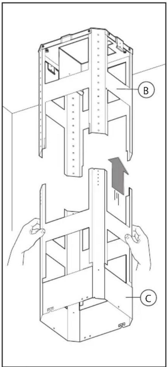
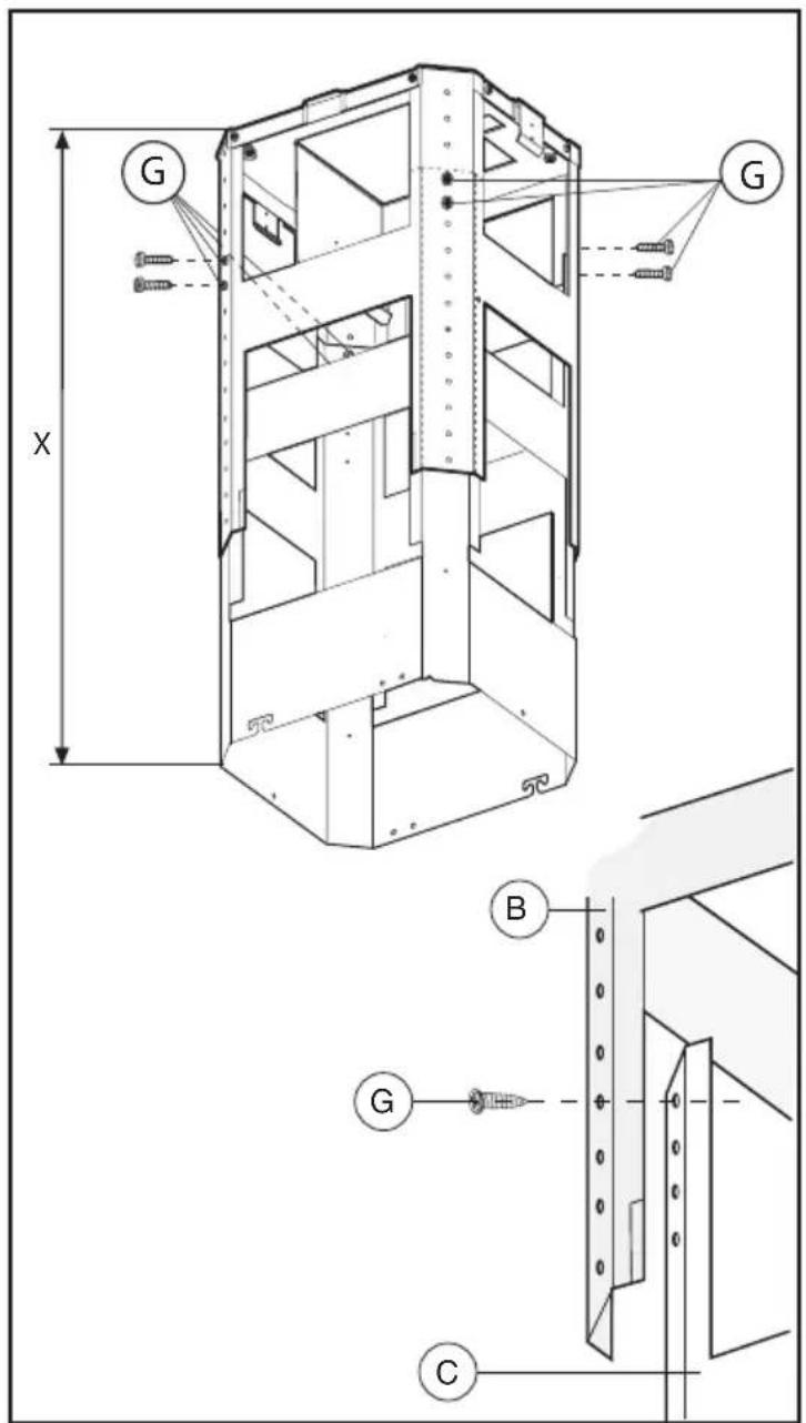
Fig.5 Fig.6
natural_image
Technical illustration of a mechanical assembly with hands installing a coiled spring component (no text or symbols present)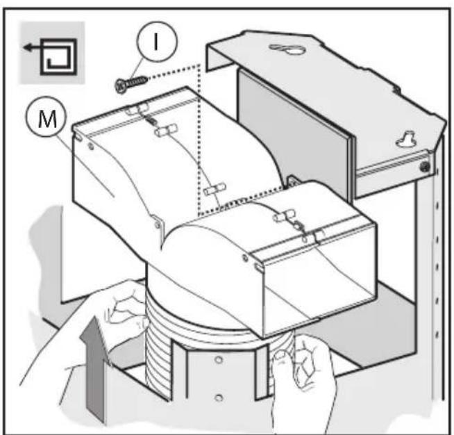
Fig.8Fig.7
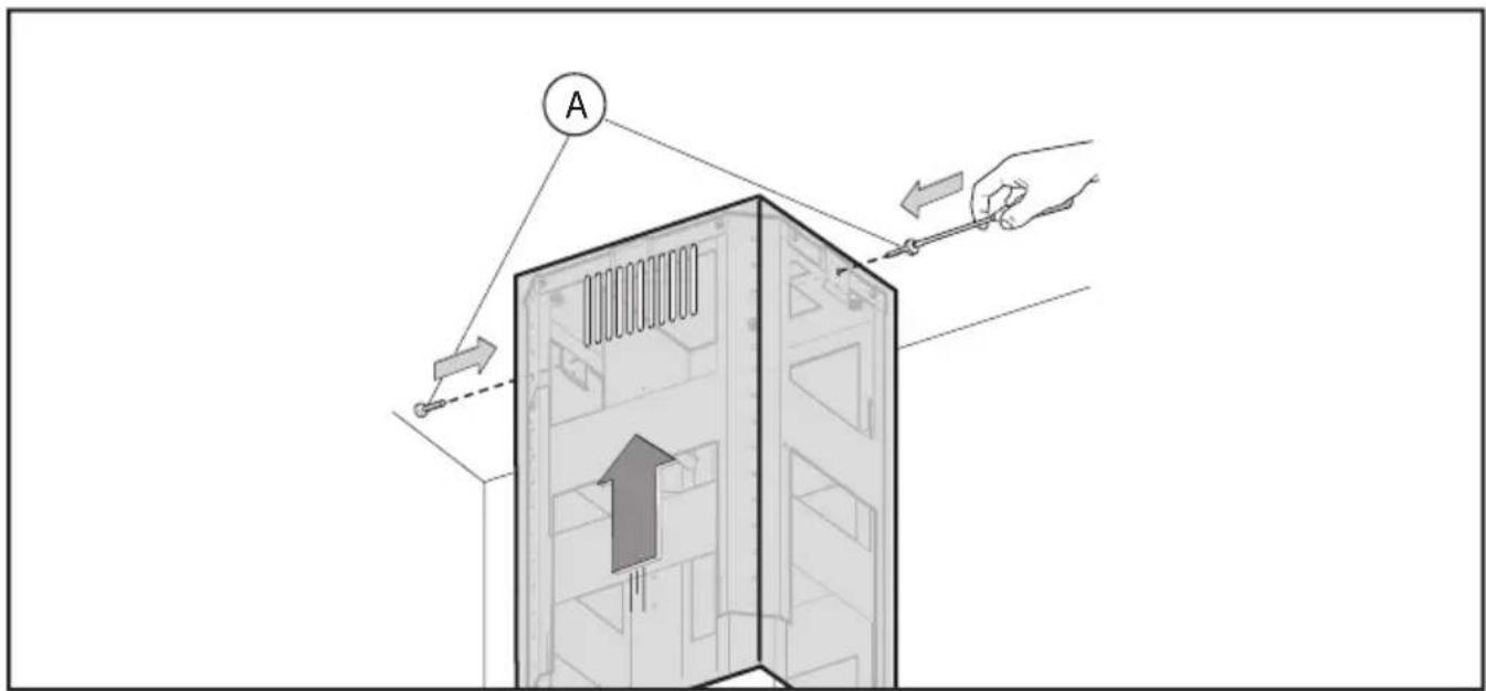
Fig.9
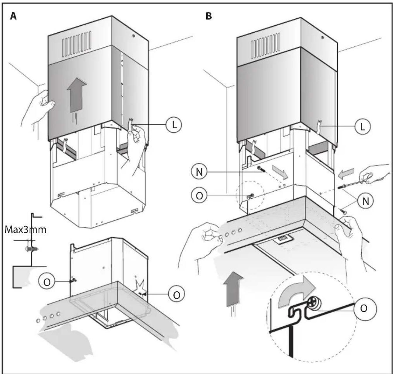
Fig.10
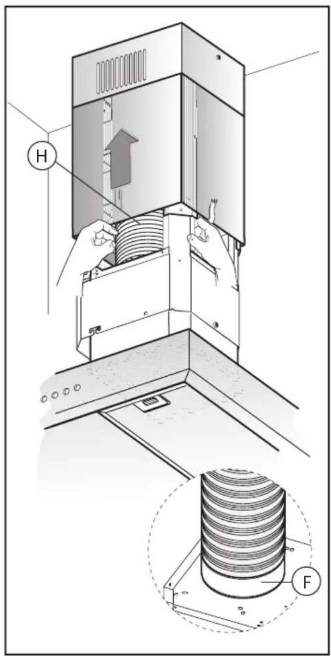
Fig.11
natural_image
Isometric illustration of a vertical elevator with a downward arrow indicating airflow or pressure, mounted on a floor (no text or symbols)Fig.12
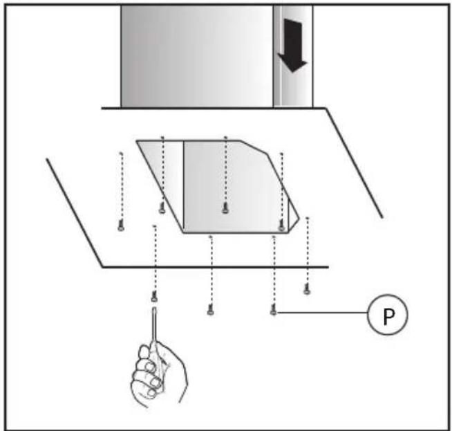
Fig.13
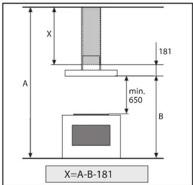
Fig.14
natural_image
Illustration of a hand using a ruler to measure a curved object inside a shelf (no text or symbols)Fig.15
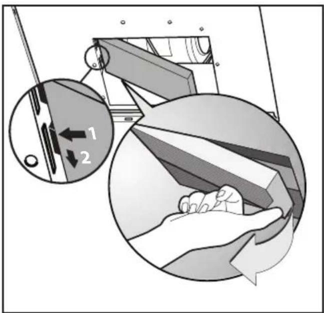
Fig.16
natural_image
Illustration of hands holding a rectangular electronic component with a black arrow indicating force or movement (no text or symbols)Fig.17
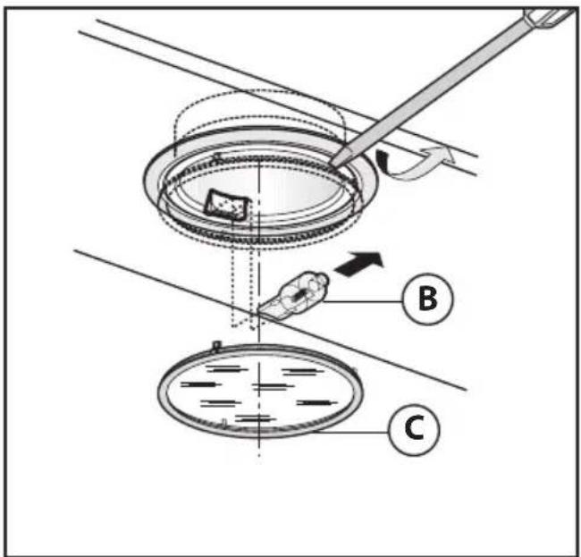
Fig.18 Fig.19
flowchart
graph TD
    A["Sun Icon"] --> B["A"]
    C["0"] --> D["B"]
    E["1"] --> F["C"]
    G["2"] --> H["D"]
    I["3"] --> J["E"]
    K["T"] --> L["F"]
ALLGEMEINES
- Commandes(Fig.19):
Carefullyread the following important information regarding installation safety and maintenance. Keep this information booklet accessible for further consultations. The appliance has been designed for use in the ducting version (air exhaust to the outside – Fig.1B), filtering version (air circulation on the inside – Fig.1A) or with external motor (Fig.1C).
SAFETY PRECAUTION
- Take care when the cooker hood is operating simultaneously with an open fireplace or burner that depend on the air in the environment and are supplied by other than electrical energy, as the cooker hood removes the air from the environment which a burner or fireplace need for combustion. The negative pressure in the environment must not exceed 4Pa (4x10⁻⁵ bar). Provide adequate ventilation in the environment for a safe operation of the cooker hood. Follow the local laws applicable for external air evacuation.
Before connecting the model to the electricity network:
-Control the data plate (positioned inside the appliance) to ascertain that the voltage and power correspond to the network and the socket is suitable. If in doubt ask a qualified electrician.
-If the power supply cable is damaged, it must be replaced with another cable or a special assembly, which may be obtained direct from the manufacturer or from the Technical Assistance Centre.
2. Warning!
In certain circumstances electrical appliances may be a danger hazard.
A) Do not check the status of the filters while the cooker hood is operating.
B) Donottouchbulbsor adjacentareas, during or straight after prolonged use of the lighting installation.
C) Flambè cooking is prohibited underneath the cooker hood.
D) Avoid free flame, as it is damaging for the filters and a fire hazard.
E) Constantly check food frying to avoid that the overheated oil may become a fire hazard.
F) Disconnect the electrical plug prior to any maintenance.
G) This appliance is not intended for use by youngchildren or infirm persons without supervision.
H) Youngchildren should be supervised to ensure they do not play with the appliance
I) There shall be adequate ventilation of the room when the rangehood is used at the same time as appliances burning gas or other fuels.
L) There is a risk of fire if cleaning is not carried out in accordance with the instructions.
This appliance conform to the European Directive EC/2002/96, Waste Electrical and Electronic Equipment (WEEE). By making sure that this appliance is disposed of in a suitable manner, the user is helping to prevent potential damage to the environment or to public health.
The ⚡ symbol on the product or on the accompanying pa-
perwork indicates that the appliance should not be treated as domestic waste, but should be delivered to a suitable electric and electronic appliance recycling collectionpoint. Follow local guidelines when disposing of waste. For more information on the treatment, re-use and recycling of this product, please contact your local authority, domestic waste collection service or the shop where the appliance was purchased.
INSTALLATION INSTRUCTIONS
Assembly and electrical connections must be carried out by specialised personnel.
•ElectricConnection:
This is a class I, appliance and must therefore be connected to an efficient earthing system.
-The appliance must be connected to the electricity supply as follows:
BROWN = L line
BLUE = N neutral
YELLOW/GREEN = ⏱ earth.
The neutral wire must be connected to the terminal with the N symbolwhile the YELLOW/GREEN, wiremustbe connected to the terminal by the earth symbol ⏻.
When connecting the appliance to the electricity supply, make sure that the mains socket has an earth connection. After fitting the ducted cooker hood, make sure that the electrical plug is in a position where it can be accessed easily. If the appliance is connected directly to the electricity supply, an omnipolar switch with a minimum contact opening of 3 mm must be placed in between the two; its size must be suitable for the load required and it must comply with current legislation.
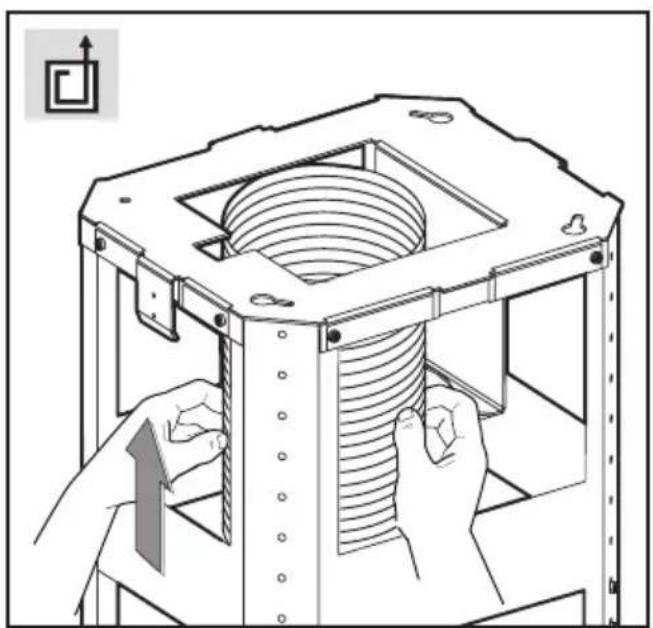
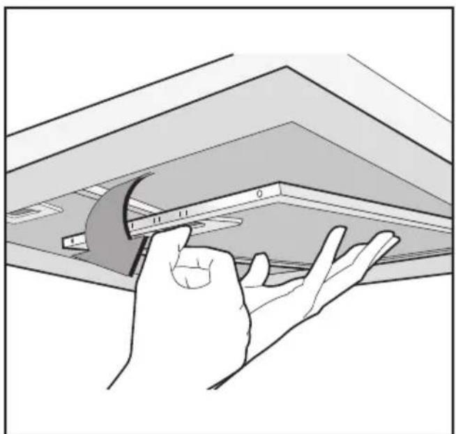
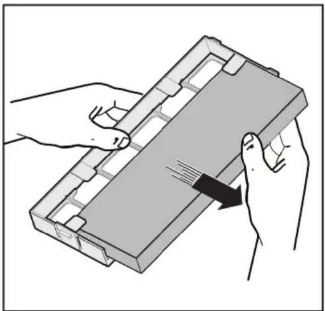
- The minimum distance between the support surfaces of the cooking pots on the cooker top and the lowest part of the cooker hood must be at least 65 cm. If a connection tube composed of two parts is used, the upper part must be placed outside the lower part. Do not connect the cooker hood exhaust to the same conductor used to circulate hot air or for evacuating fumes from other appliances generated by other than an electrical source. Before proceeding with the assembly operations, remove the anti-grease filter(s) (Fig.15) so that the unit is easier to handle.
- Were recommend the use of an air exhaust tube which has the same diameter as the air exhaust outlet hole. If a pipe with a smaller diameter is used, the efficiency of the product may be reduced and its operation may become noisier.
In the case of assembly of the appliance in the suction version prepare the hole for evacuation of the air.
•Hoodassembly:
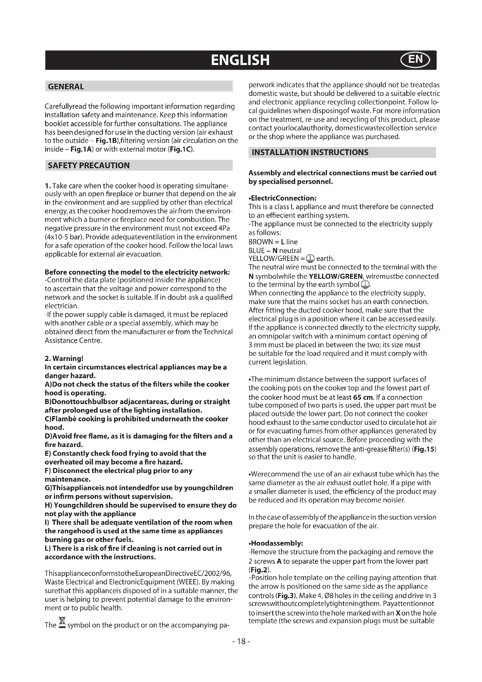
-Remove the structure from the packaging and remove the 2 screws A to separate the upper part from the lower part (Fig.2).
-Position hole template on the ceiling paying attention that the arrow is positioned on the same side as the appliance controls (Fig.3). Make 4, ∅8 holes in the ceiling and drive in 3 screwwithoutcompletelytighteningthem. Payattentionnot to insert the screw into the hole marked with an X on the hole template (the screws and expansion plugs must be suitable
for the type of wall).
-Take the upper part of the structure B (Fig.4) and insert the 3 slots onto the 3 screws that are not completely tightened. Rotate slightly to fit (Fig.4). Drive in the fourth screw X and tighten the remaining 3 to allow definitive blocking of the upper part of structure B.
-Take the lower part of the telescopic structure C and insert it into the upper structure B (Fig.5). Adjust the height by referring to the amounts X indicated in Fig.14 and block it using the 8 screws G that are supplied (Fig.6).
- Suction version: Fix the flexible pipe to the prepared air evacuation hole (Fig.7).
-Filteringversion:Connect the air exhaust pipe to the recirculationair deflectorM, andtighten the screwI, asshown in Fig.8. The carbon filters must be fitted inside the suction hood as shown in Fig.16. There are two different types of active carbon filters: long-lasting regenerable active carbon filters (washable) (Fig.17) and standard non-regenerable active carbon filters (Fig.16).
-Take the upper chimney piece and fix it to the structure using the 2 screws A (Fig.9). Join the lower chimney piece with the upper one and fix it carefully using adhesive tape L (Fig.10A).
-Unscrew the 2 screws O, max 3 mm (Fig.10A). Insert the suction unit inside the structure paying attention that the previously unscrewed screws O, hook into the slots in the lower part as indicated in (Fig.10B). Drive in the 3 screws N (supplied) and tighten the 2 screws O (Fig.10B).
-Fix the air evacuation pipe H (not supplied) onto the connection flange F (Fig.11).
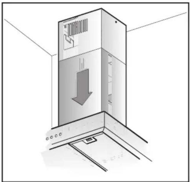
-Remove adhesive tape L and rest the lower chimney piece above the cooker hood (Fig.12).
-If necessary, fix the lower duct to the hood from the inside, using the screws P (Fig.13).
USE AND MAINTENANCE
- We recommend that the cooker hood is switched on before any food is cooked. We also recommend that the appliance is left running for 15 minutes after the food is cooked, in order to thoroughly eliminate all contaminated air.
The effective performance of the cooker hood depends on constant maintenance; the anti-grease filter and the active carbon filter both require special attention.
•Theanti-greasefilteris responsible retaining the grease particles suspended in the air, therefore it is subject to clogging with variable frequency according to the use of the appliance.
- To prevent the danger of possible fires, at least every 2 months one must wash the anti-grease filters by hand using non-abrasive neutral liquid detergents or in the dishwasher at low temperatures and on short cycles.
- After a few washes, colour alterations may occur. This does not give the right to claim their replacement.
- Theactivecarbonfilters are used to purify the air that is sent back into the room and its function s to mitigate the unpleasant odours produced by cooking.
- The non-regenerable active carbon filters must be replaced at least every 4 months. The saturation of the active charcoal depends on the more or less prolonged use of the appliance, on the type of kitchen and on the frequency with which anti-grease filter is cleaned.
- Regenerable active charcoal filters must be washed by hand, with non abrasive neutral detergents, or in the dishwasher at a maximum temperature of 65^ C (the washing cycle must be complete without dishware). Remove excess water without damaging the filter, remove the plastic parts, and let the mat
dry in the oven for at least 15 minutes approximately at a maximum temperature of 100^ C. To keep the regenerable charcoal filter functioning efficient this operation must be repeated every 2 months. These must be replaced at least every 3 years or when the mat is damaged.
- Before remounting the anti-grease filters and theregenerable reactive charcoal filters it is important that they are completely dry.
- Clean the hood frequently, both internally and externally, using a cloth dampened with denatured alcohol or neutral liquid detergents that are non abrasive.
- The lighting .system is designed for use during cooking and not for the prolonged general lighting of the room. The prolonged use of the lighting system significantly decreases the average duration of the bulbs.
- Attention: The non compliance with the hood cleaning warnings and with the replacement and cleaning of the filters entails risk offires. One therefore recommends keeping to the suggested instructions.
•Replacinghalogenlightbulbs(Fig.18):
To replace the halogen light bulbs B, remove the glass pane C using a lever action on the relevant cracks.
Replace the bulbs with new ones of the same type.
Caution: Do not touch the light bulb with bare hands.
- Commands(Fig.19):
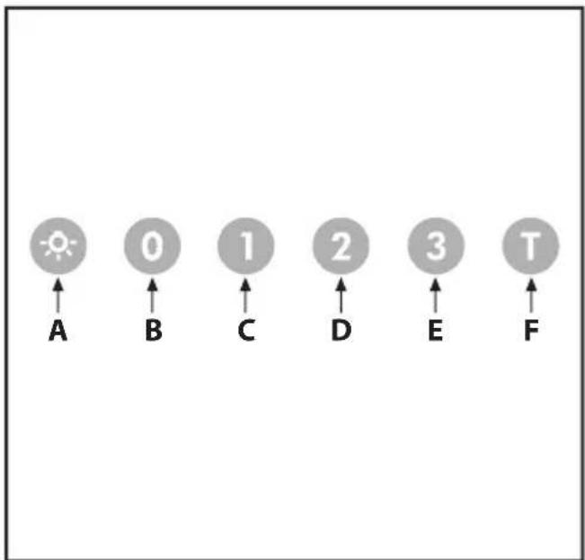
The key symbols are explained below:
A = LIGHT
B = OFF
C = SPEED I
D=SPEED II
E = SPEED III
F = AUTOMATIC STOP TIMER - 15 minutes (*)
- If your appliance does not have the INTENSIVE speed function, press key E for two seconds and it will be activated for 10 minutes after which it will return to the previously set speed. When the function is active the LED flashes. To interrupt it before the 10 minutes have expired press key E again.
- CleanAir:
By pressing key F fortwo seconds (with the hood switched off) the "clean air" function is activated. This function switches the appliance on for ten minutes every hour at the first speed. As soon as this function is activated the motor starts up at the first speed for ten minutes. During this time key F and key C must flash at the same time. After ten minutes the motor switches off and the LED of key F remains switched on with a fixed light until the motor starts up again at the first speed after fifty minutes and keys F and C start to flash again for ten minutes and so on. By pressing any key for the exclusion of the hood light the hood will return immediately to its normal functioning (e.g. if key D is pressed the "clean air" function is deactivated and the motor moves to the 2nd speed straight away. By pressing key B the function is deactivated).
(*) The "AUTOMATIC STOP TIMER" delays stopping of the hood, which will continue functioning for 15 minutes at the operating speed set at the time this function is activated.
•Anti-greaseandactivecarbonfiltersaturation:
- After 30 hours of work, the key A flashes every 2 sec.; in that event, the anti-grease and active carbon filter must be cleaned, if present.
-After 120 hours of work, the key A flashes every 0.5 sec.; in thatevent, the standard active carbon filtersmust be replaced, if present.
Once the filter has been cleaned and put back, the electronic memory must be reactivated, by holding the key A pressed for about 5 sec. until it stops flashing.
- If the button A does not stop flashing, repeat the operation with the motor on.
THE MANUFACTURER DECLINES ALL RESPONSIBILITY FOR EVENTUAL DAMAGES CAUSED BY BREACHING THE ABOVE WARNINGS.
GENERALIDADES
INSTALLATIE INSTRUCTIES
C = knop EERSTE SNELHEID
D=knop TWEEDW DERDE SNELHEID
E = knop DERDE SNELHEID
F = knop TIMER AUTOMATISCHE ONDERBREKING na 15 minuten (*)

- Modifications
- ES
- ALLGEMEINES
- - Commandes(Fig.19):
- SAFETY PRECAUTION
- Before connecting the model to the electricity network:
- Warning!
- INSTALLATION INSTRUCTIONS
- Assembly and electrical connections must be carried out by specialised personnel.
- •ElectricConnection:
- •Hoodassembly:
- USE AND MAINTENANCE
- - Before remounting the anti-grease filters and theregenerable reactive charcoal filters it is important that they are completely dry.
- •Replacinghalogenlightbulbs(Fig.18):
- - Commands(Fig.19):
- - CleanAir:
- •Anti-greaseandactivecarbonfiltersaturation:
- GENERALIDADES
- INSTALLATIE INSTRUCTIES
Brand : V-ZUG
Model : DISL10
Category : Range hood