DH 600 - Humidifier TROTEC - Free user manual and instructions
Find the device manual for free DH 600 TROTEC in PDF.


| Product type | Professional air dehumidifier |
| Brand | Trotec |
| Model | DH 600 |
| Dimensions (L × W × H) | 1730 × 1250 × 1600 mm |
| Weight | 497 kg |
| Power supply | 400 V ~3N, 50 Hz |
| Rated current | 26 A (standard) |
| Power consumption | 10.4 kW |
| Dehumidification capacity | 25 l/h (at 20 °C, 75 % RH) |
| Nominal air flow | 9,000 m³/h |
| Max. static pressure (standard) | 80 Pa |
| Condensate drain connection | 1½ G thread |
| Refrigerant | R407c, 14 kg |
| Operating temperature range | -15 °C to 40 °C (Y models) |
| Humidity controller | 20 - 80 % RH, adjustable |
| Automatic defrost function | Yes (active at low temperature) |
| LED indicators | Voltage (red), Error (yellow), Defrost (white) |
| Phase failure protection | Integrated protection relay |
| Sound level | 63 dB(A) |
| Required free air surface | 1.1 m² minimum |
| Options | Soft start, condensate pump, remote control RCU |
| Maintenance | Regular filter cleaning; checking air channels |
| Spare parts | Available from authorized dealers |
| Accessories | Blowing box, air heater, filters |
Frequently Asked Questions - DH 600 TROTEC
User questions about DH 600 TROTEC
0 question about this device. Answer the ones you know or ask your own.
Ask a new question about this device
Download the instructions for your Humidifier in PDF format for free! Find your manual DH 600 - TROTEC and take your electronic device back in hand. On this page are published all the documents necessary for the use of your device. DH 600 by TROTEC.
USER MANUAL DH 600 TROTEC
INHALTSVERZEICHNIS
This publication replaces all previous publications. No part of this publication may be reproduced or processed using electronic systems, duplicated or distributed without our prior written consent. Subject to technical modifications. All rights reserved. Names of goods are used without guarantee of free usage and used for the most part according to the manufacturers' syntax. The names of goods used are registered and should be considered as such. We reserve the right to modify the design in the interest of ongoing product improvement and to carry out modifications regarding the products' shape or colour. The scope of delivery may deviate from the product description. All due care has been taken in compiling this document. We accept no liability for any errors or omissions. © TROTEC®
01. SAFETY INSTRUCTIONS
The dehumidifier comprises electric as well as rotating parts. We therefore strongly recommend that you DO NOT carry out any repair or maintenance work on the unit. All work on such units should ONLY be carried out by trained and skilled staff (see guarantee). The unit must be earthed before any parts of the housing are removed and any work inside the unit is carried out.
02. INSTALLING THE UNIT
It is particularly important that proper thought is given to installing the unit as this is crucial to the dehumidifier's performance.
2.1 INSTALLATION SITE
- Please check to ensure that the dehumidifier you have been delivered is in fact the model you ordered (power supply, factory applied accessories).
- Check your unit, especially the evaporator, for damage (small indentations on the fan blades do not in any way affect the dehumidifier's performance). If your unit is damaged, please make a note of the type and extent of damage on the delivery note while the haulier is present and report the damage via registered mail to the haulier's company.
- Ensure that the unit is adequately protected against any damage if you are not planning on installing it immediately.
- Install the unit on a flat, level and solid surface which you are sure can carry the weight of your dehumidifier. Ensure that the weight is evenly distributed in case of wooden flooring.
- Ensure that water cannot collect under the unit. We recommend placing the unit on an approximately 100 mm high pedestal to allow the condensate to run off more easily.
- Leave a distance of at least 500 mm to any walls or other objects in order to allow service and repair work to be carried out (see installation plans).
- All the models in the Trotec range are designed to run extremely silently. This allows you to make the most of your dehumidifier by installing it where it is needed mos and to place it so that the air intake and discharge duct is positioned parallel to the office desks or your workplace.
- Please ensure that loose dirt or any similar substances cannot block or obstruct the air intake duct or protective grille.
Your dehumidifier should be installed either in the room that you wish to dehumidify or in a neighbouring room or adjacent area. Under no account should you place your dehumidifier in a cold area, e. g. outside the building.
2.2 AIR CIRCULATION
It is important that you ensure that the air is distributed evenly throughout the room in order to ensure that the humidity is drawn out of the ambient air as effectively as possible and that the humidity value you have selected is maintained constantly. Your dehumidifier must be able to draw in moist air and distribute the air which has been dried to areas which are commonly affected by high levels of moisture (e.g. windows). This is why your dehumidifier is equipped with special ventilation channels and ducts.
The drier and the ventilation channels work at normal temperatures. If they come into contact with unheated rooms because the ventilation channels are conducted through unheated cellars or attics for example, then these channels must be insulated accordingly.
Drawing in air from moister areas:
The moist air must be fed into the drier in as small amounts as possible. There is no need for ventilation channels if the dehumidifier is placed in an adjoining room.
Discharging dry air back into the room:
You will find that it is often necessary to install ventilation channels to ensure that the dried air is distributed as evenly as possible. See the technical data sheet to find out which ventilation channels, ventilation grilles, grilles and air heating batteries are suitable for which specific quantities of air and which different pressure values.
IMPORTANT NOTES:
- It must be ensured that the nozzle which measures the relative humidity at the air intake duct is also able to measure the moisture from any installed ventilation channels (see installation plan).
- All models are standard equipped with a nozzle for the discharged air.
-
The air discharge nozzles and air filters are available from specialist stores. DO NOT drill into the unit to fit either the nozzle or air filter.
-
A flexible adapter made of rubber or fabric should be placed between the ventilation channels and the nozzle to prevent any vibrations from being transferred.
- Remove any cover lids or air grilles before the air ventilation channels are connected.
- Check the unit, the grilles and the airflow thoroughly when you have completed installing the unit. The air flow must correspond to the amount stated on the technical data sheet (± 10 %) and should be adjusted, if necessary, using the main sluice valve. If the air flow does not correspond to the prescribed amount, then the performance of your dehumidifier will not be achieved.
- TABLE 1. Open space which is necessary to ensure that sufficient air flow is guaranteed when the unit is installed in a separate room and wall breakthroughs are planned.
Model DH150:
Minimum open space air inlet amount = 0.35 m².
Model DH300:
Minimum open space air inlet amount = 0.57 m².
Model DH600:
Minimum open space air inlet amount = 1.1 m 4 .
If more than one unit has been installed in a closed area, the open spaces which are necessary to ensure that the dehumidifiers perform as intended can be added together to form a common air inlet opening. The air discharge ducts should be connected to separate ventilation channels or separated by nonreturn valves in order to prevent the air from flowing back into other machines.
2.3 DRAINING OFF THE WATER
- The water which condenses on the evaporator blades is collected in a tank. It is therefore necessary for the dehumidifier to be placed on a flat and level and raised surface which allows the water to drain off and which prevents the water in the tank from running over. The dehumidifiers from Trotec are equipped with the following connecting points to drain off the condensed water.
Model DH150:
22 mm connecting pipe
Model DH300:
G 3/4 -inch pipe thread connector
Model DH600:
G 1½-inch pipe thread connector
2.4 ELECTRICAL INSTALLATION (CABLING AND POWER SUPPLY)
- The electrical installation must fulfil the requirements of the most current existing local guidelines.
- The power supply must be protected by fuses and a circuit breaker for the motor (see technical data sheet). A cut-off switch must also be installed next to the unit.
- All machines and appliances must be properly grounded. We recommend installing a residual current operated protective device (RCD).
- IMPORTANT:
The performance values can only be achieved if the following voltage and frequency limits are observed: Units with a single phase: Nominal voltage 230 V, ±10 % Units with three phases: Nominal voltage 400 V ±10 % Frequency nominal frequency 50 Hz: ±5 %
IMPORTANT: These voltages must be given when the dehumidifier is operated at full power.
PLEASE NOTE: All the units are equipped with a phase failure relay. If a phase is missing or a there is no clockwise rotating field, the relay control lamp is off and the drier will not run.
03. CONTROL ELEMENTS AND INDICATOR LAMPS
External Operating Console:
- POWER SUPPLY – RED:
Lights up when the power supply of the dehumidifier is switched ON. - FAULT – YELLOW:
Lights up when there is a fault at the internal safety switch or when the locking chain is open.
- DEFROST – WHITE:
Lights up when the dehumidifier is switched to Defrost mode. This occurs automatically at low temperatures and is NOT a fault! The dehumidifier switches back automatically to normal mode when the defrosting cycle is completed.
- ON/OFF switch:
Only for the DH150. This switch should only be used when you are not planning on using your dehumidifier over a longer period or when you wish to disconnect it from the main power supply.
• STANDBY SWITCH:
Only for the DH300/600. This switch should only be used when you are not planning on using your dehumidifier over a longer period or when you wish to disconnect it from the main power supply.

When the unit is switched on for the first time, or when the unit has been disconnectted from the power supply for longer than an hour, the STANDY SWITCH has to be switched to standby. The dehumidifier must remain in standby for 12 hours before you can switch to normal mode.
Internal control elements:
- The adjustable internal relative humidity control (range 20/80 %) should be set to 60 % to achieve a pleasant room climate in the home or office while producing as little condensed water as possible. (At 20 % more moisture is drawn out of the ambient air than at 80 %).
-
The adjustable temperature control should be set to the highest temperature you wish to have in the area you wish to dehumidify.
-
Fan speed switch. This switch can be used to decide whether the relative humidity control switches the fan on or off with the compressor or whether it is allowed to run permanently. Air circulation is greatly improved when the fan runs permanently. This results in less condensation water because areas of air are prevented from standing still.
- The adjustable air temperature control on the inside of the heating attachment has to be set to the lowest temperature when the optional rotating heating attachment has been attached.
- Connect the RCU control in the dehumidifier with the help of the supplied cable to the terminal board on the inside of the RCU unit. Thread the cable through the duct seal or the cable duct opening at the base of the unit and use the strain relief clamps.
04. TROUBLESHOOTING

Disconnect the unit from the mains power supply before you remove any cover pa-r before you climb into the machine.
Before you decide to contact our Product Support Department, please have a qualified electrician check your unit according to the following check list. Do not change any of the internal control settings. They are factory set and sealed. If you need any help or are unsure about anything regarding your product, please contact our Customer Support Team:
Tel.: +49 2452 969 - 400 · Fax: +49 2452 962 - 200
E-mail: info@trotec.de.
Check list
Fan and compressor won't run
| Indicator | |||
| Function Colour Status | |||
| Power supply | red | Off | Check to ensure that the fuses for the supply cable are OK. |
| Fault | yellow | Off | |
| Defrost | white | Off | Check to ensure that the ON/OFF switch is ON (DH 150 only). |
| On/Off | red | Off | |
Fan is running, compressor is off
| Indicator | |||
| Function Colour Status | |||
| Power supply | red | On | Check to ensure if the dehumidifier's humidistat is switched on and that the air temperature is not above the temperature setting of the humidistat. |
| Fault | yellow | Off | Check the internal fuses/safety switch. |
| Defrost | white | Off | Check if the standby switch is switched to ON. |
| On/Off | red | On | |
| Indicator | |||
| Function Colour Status | |||
| Mains supply | red | On | Check to ensure that the air flow is not obstructed. Reset the high pressure switch (only for DH 300 & DH 600). |
| Fault | yellow | On | Check the overheat protection at the soft start and at the optional heater. |
| Defrost | white | Off | |
| On/Off | red | Off | Check the fan to see in which direction it rotates (only for DH 300 & DH 600). |
| Indicator | |||
| Function Colour Status | |||
| Mains supply | red | On | Check if the air temperature is above 0°C (DH 150) and above -15 °C (DH 300 & DH 600). |
| Fault | yellow | Off | |
| Defrost | white | On | Please note: It is normal for the dehumidifier to switch automatically to defrost mode once every hour. |
| On/Off | red | On | |
- technical Data
| MODEL DH(W)150AX/BX DH(W)300BY DH(W)600BY | ||||||
| Performance Data | ||||||
| Dehumidification performance l/h 6·25 12·5 25 | ||||||
| Power output (DH model) kW 5·5 15·5 25 | ||||||
| Power input kW 2·9 7·3 10·4 | ||||||
| Electrical Data | ||||||
| Supply voltage 1∅ 230v~1N 50 hz N/A N/A | ||||||
| Supply voltage 3∅ | 400v ~3N 50 hz | |||||
| Fan option | STD | "F" | STD | "F" | STD | "F" |
| max. preliminary fuse 1∅ ampere | 30 | 30 | N/A | N/A | ||
| max. preliminary fuse 3∅ ampere | 16 | 16 | 25 | 40 | ||
| max. nominal current 1∅ ampere | 19 | 20 | N/A | N/A | ||
| max. nominal current 3∅ ampere | 8·3 | 9·9 | 16 | 17 | 26 | 27 |
| Starting current 1∅ STD M/C ampere | 61 | N/A N/A | ||||
| Starting current 1∅ "S" ampere | 28 | N/A N/A | ||||
| Starting current 3∅ STD ampere | 30 | 69 | 135 | |||
| Starting current 3∅ "S" ampere | 13 | 40 | 55 | |||
| Fan heater | ||||||
| When equipped with a rotating cap and a fan heater: | ||||||
| max. output kW | 9 | N/A N/A | ||||
| max. power input 1∅ ampere | 36 | N/A N/A | ||||
| max. power input 3∅ ampere | 12 | N/A N/A | ||||
| max. preliminary fuse 1∅ ampere | 50 | N/A N/A | ||||
| max. preliminary fuse 3∅ ampere | 16 | N/A N/A | ||||
| Air Flow Volume Data | ||||||
| Nominal air flow rate m3/h | 2200 | 5000 | 9000 | |||
| Piping max. stat. pressure loss STD M/C Pa | 30 | 60 | 80 | |||
| Piping max. stat. pressure loss "F" M/C Pa | 170 140 160 | |||||
| When equipped with a rotating cap and a fan heater: | ||||||
| Piping max. stat. pressure loss STD M/C Pa | 0 | N/A | ||||
| Piping max. stat. pressure loss "F" M/C Pa | 140 | N/A | 80 | |||
| MODEL DH(W)150AX/BX DH(W)300BY DH(W)600BY | |||
| Air Flow Volume Data | |||
| Condensate water connection 22 mm pipe | connector | G 11/2 “ G 11/2 “ | |
| Dimensions | |||
| Width (unpacked) mm 660 980 1730 | |||
| Depth (unpacked) mm 660 720 1250 | |||
| Height (unpacked) mm 1313 1435 1600 | |||
| Weight (unpacked) kg 130 220 497 | |||
| Other Information | |||
| Weight refrigerant R407c (STD DH) kg 2·5 11·5 14 | |||
| Sound level | 58 | 66 | 63 |
Please Note:
1) Performance data at 20 °C, 75 %RH (Water at 26 °C).
2) Minimum air temperature 0 °C for "X" models and 15 °C for "Y" models.
3) Trotec reserves the right to carry out changes and modifications.
06. Installation plans
Dehumidifier DH 150
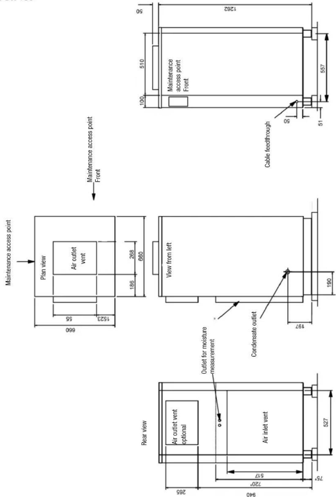
Dehumidifier DH 150
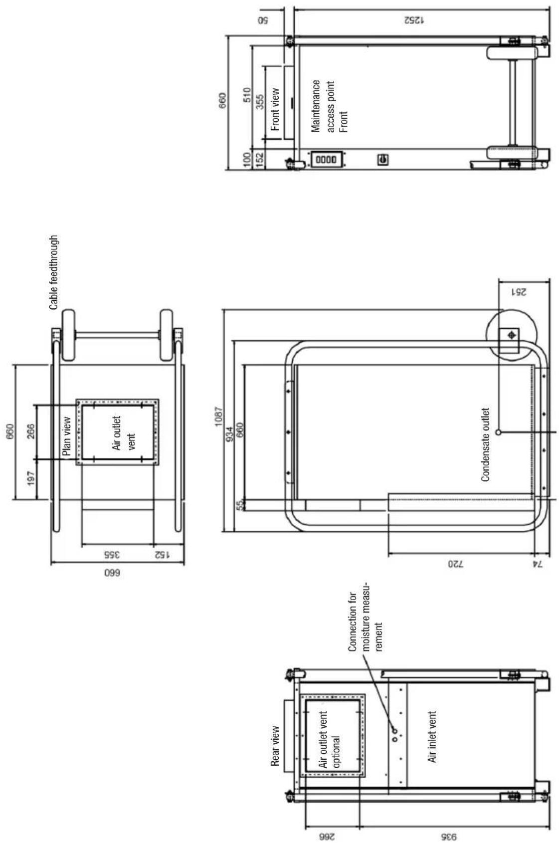
Dehumidifier DH 300
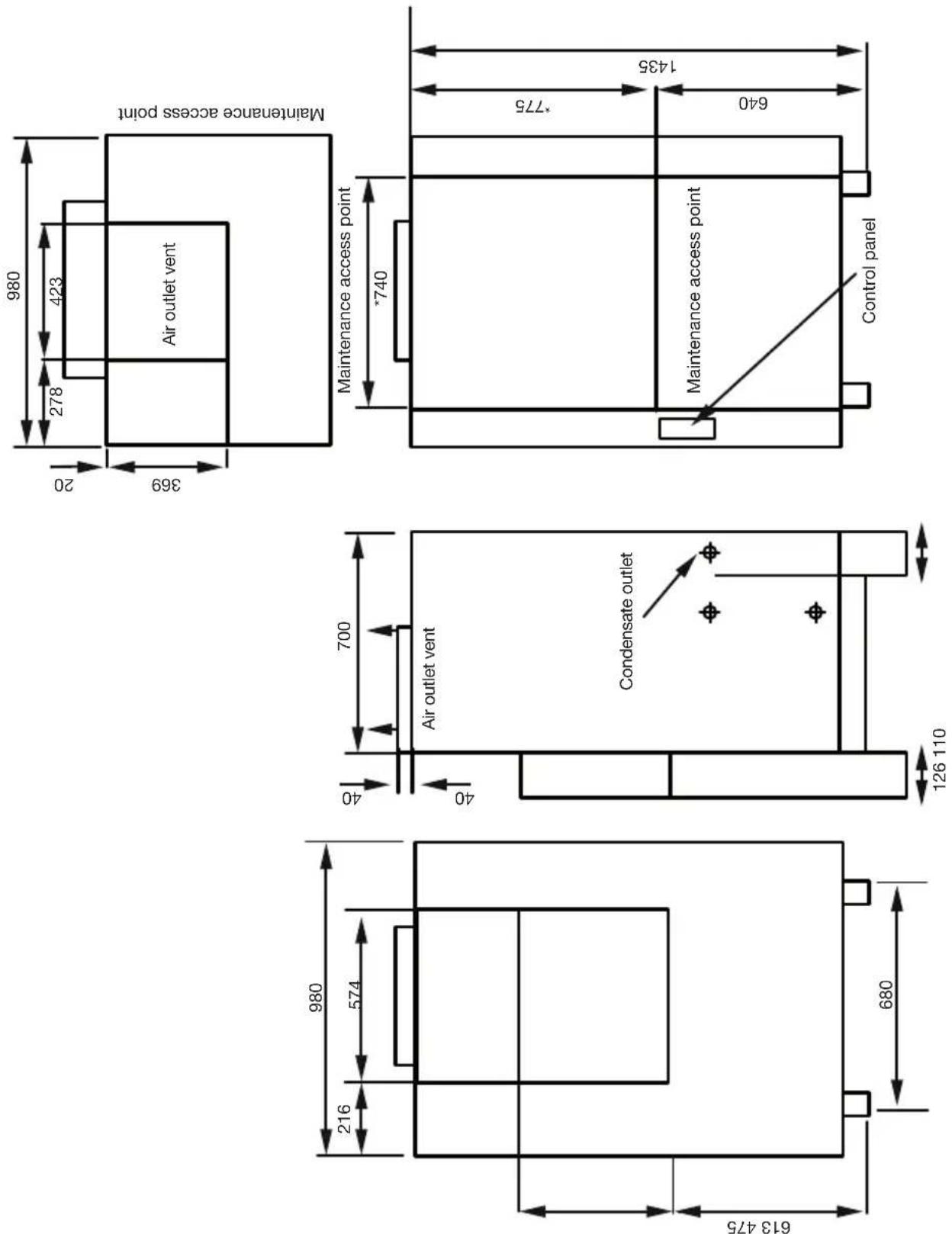
Dehumidifier DH 600
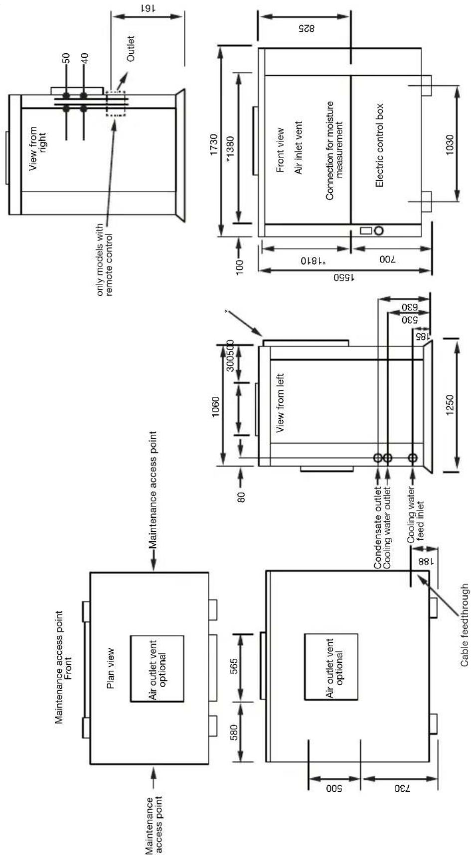
Note: Dimensions marked * refer to dimensions of INLET DUCT FLANGE KIT option (50 mm deep)
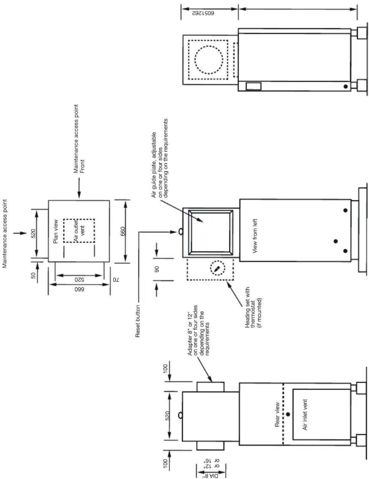
Air discharge attachment DH 150
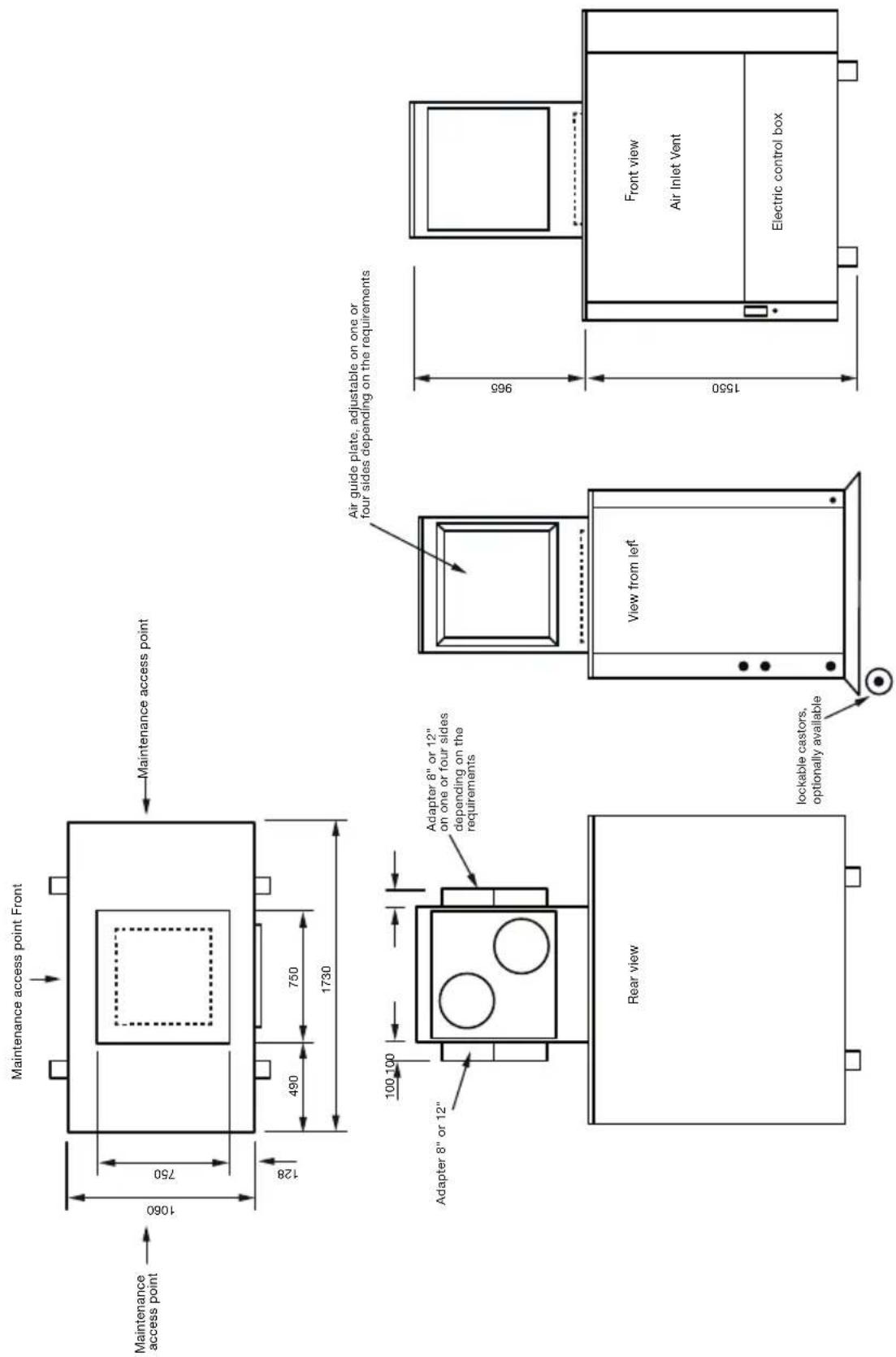
Air discharge attachment DH 600
07. circuit DlaGraMs
Declaration of Conformity
® GmbH&TEG KG
Grebbener Straße 7
D-52525 Heinsberg
hereby declares that due to their construction and design the following dehumidifiers, including those products introduced into the market by us, comply with the EU guidelines and directives as stated below.
Important information:
This declaration is no longer legally valid if the unit is not used, installed or maintained as intended or when any unauthorised changes are made to the unit.
Type of unit: Dehumidifier
Series/Model: DH 150/300/600
Applicable regulations:
MA-RL 2006/42/EC
NS-RL 73/23/EEC
EMC-RL 2004/108/EG
WEEE 2002/96/EC
Machine guideline
Low voltage guideline
EMC guideline
Electrical and Electronics
Equipment Safety Act
(2003/108/EC)
Applied norms:
EN ISO 12100-1:2003, EN ISO 12100-2:2003, EN ISO 13857:2008
EN 60335-1:2002, EN 60335-2-40:2002, EN 55014-1:2006,
EN 55014-1:1997+A1:2001+A2:2008, EN 61000-3-2:2006,
EN 61000-3-3:2008; EN 61000-4-2:2009; EN 61000-4-4:2004;
EN 61000-4-5:2006; EN 61000-4-6:2007; EN 61000-4-11:2004
Heinsberg, 21. February 2012
PMProduct Management
SOMMAIRE

- INHALTSVERZEICHNIS
- SAFETY INSTRUCTIONS
- INSTALLING THE UNIT
- 2.1 INSTALLATION SITE
- 2.2 AIR CIRCULATION
- DRAWING IN AIR FROM MOISTER AREAS
- DISCHARGING DRY AIR BACK INTO THE ROOM
- IMPORTANT NOTES
- MODEL DH150
- MODEL DH300
- MODEL DH600
- 2.3 DRAINING OFF THE WATER
- 2.4 ELECTRICAL INSTALLATION (CABLING AND POWER SUPPLY)
- IMPORTANT
- CONTROL ELEMENTS AND INDICATOR LAMPS
- EXTERNAL OPERATING CONSOLE
- INTERNAL CONTROL ELEMENTS
- TROUBLESHOOTING
- CHECK LIST
- PLEASE NOTE
- INSTALLATION PLANS
- DEHUMIDIFIER DH 300
- CIRCUIT DLAGRAMS
- DECLARATION OF CONFORMITY
- IMPORTANT INFORMATION
- APPLICABLE REGULATIONS
- APPLIED NORMS
- SOMMAIRE
Brand : TROTEC
Model : DH 600
Category : Humidifier