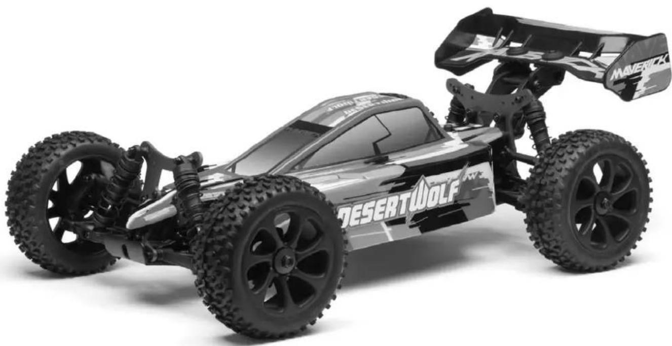
DesertWolf 18th RTR Brushless Buggy - Remote control toy Maverick - Free user manual and instructions
Find the device manual for free DesertWolf 18th RTR Brushless Buggy Maverick in PDF.

| Product Type | Radio-controlled all-terrain buggy |
| Brand | Maverick |
| Model | DesertWolf 18th RTR Brushless Buggy |
| Scale | 1/18 |
| Motor | Brushless sensorless motor |
| Electronic speed controller (ESC) | MCS-29BL-80WP, 80A continuous, 540A peak, waterproof |
| Vehicle power supply | LiPo 2S-3S battery (7.4V-11.1V) (not included) |
| Transmitter power supply | 4 AA batteries (not included) |
| Radio technology | 2.4 GHz, line-of-sight range |
| Driving functions | Forward, reverse, braking, steering |
| Driving modes | Forward with brake, Forward/reverse with brake, Rock Crawler |
| Protections | Low voltage cutoff LiPo/NiMH, overheat protection, signal loss protection, stalled motor protection |
| Recommended age | 14 years and up, under adult supervision |
| Warranty | 90 days on components (excluding damage from use) |
| Maintenance | Complete cleaning after use, lubrication of moving parts, check tightness |
| Safety | Do not use in public places or near people/animals; disconnect battery after use; do not use during a thunderstorm |
| Calibration | Required before first use; factory reset possible |
| Repairability | Spare parts available from distributor; user-repairable |
| Compliance | Directive 1999/5/EC (declaration at www.maverick-rc.com/ce) |
| Box contents | Assembled vehicle, transmitter, receiver, user manual |
Frequently Asked Questions - DesertWolf 18th RTR Brushless Buggy Maverick
User questions about DesertWolf 18th RTR Brushless Buggy Maverick
0 question about this device. Answer the ones you know or ask your own.
Ask a new question about this device
Download the instructions for your Remote control toy in PDF format for free! Find your manual DesertWolf 18th RTR Brushless Buggy - Maverick and take your electronic device back in hand. On this page are published all the documents necessary for the use of your device. DesertWolf 18th RTR Brushless Buggy by Maverick.
USER MANUAL DesertWolf 18th RTR Brushless Buggy Maverick
natural_image
Stylized black-and-white graphic of a wolf head with jagged tail, set against a cityscape background (no text or symbols)English 02
Deutsch .....14
Français ......26
Español .....38
HAVE FUN! But please read this fi rst !!
We know you will have great fun with your model, but to get the best from your purchase please read this information BEFORE you operate the model.
Table of contents
| Page | |||||
| Warranty | 2 | ||||
| Safety | Precautions | 3 | |||
| Components | 3 | ||||
| Tools | 3 | ||||
| Items | required | for | operation | 4 | |
| Charging | the | battery | pack | 5 | |
| Installing | the | batteriers | 5 | ||
| Transmitter | 5 | ||||
| Trim | Setup | 6 | |||
| Turning | on | the | power | 7 | |
| Turning | off | the | power | 7 | |
| Electronic | Speed | Control | Setup | 7 | |
| Driving | 12 | ||||
| Maintenance | after | driving | 12 | ||
| Trouble | Shooting | 13 | |||
90 Day Component Warranty
We want you to enjoy your purchase, but please read this first!
This product is covered by a 90 day component warranty from date of purchase. If any part of the product fails as a result of faulty manufacture during this period then we will repair or replace that part at our discretion.
We do not operate a new for old warranty once the product has been used.
Please note this product is not a toy and it is recommended that children 14 and under are supervised by an adult. It is the responsibility of the parent or guardian to ensure minors are given appropriate guidance and supervision.
If you suspect there is a problem with the product, for whatever reason, it is the user's responsibility to investigate and take steps to rectify the problem before further damage occurs.
Not Covered By Warranty
This is a sophisticated, high performance model and should be treated with care and respect. Every effort has been made to make this product as strong and durable as possible, however due to the nature of this product, it is still possible to break or damage parts through crashing or extreme use. Components damaged as a result of crash damage, improper use, lack of maintenance or abuse are not covered by the warranty.
How to Claim Against your Warranty
For warranty claims please first contact your supplying retailer. Do not return the product to your distributor without their prior approval. You may not need to return the product in full, only the damaged component along with a copy of your purchase receipt. In many cases it is faster and more cost effective for the user to fit the replacement part(s) to the product & therefore we reserve the right to supply parts only in these instances.
Any returned component that is inspected by your distributor and found to have an invalid warranty claim may be subject to an inspection and handling fee before it can be returned. Any repairs required as a result of neglect or misuse will be charged before any work is carried out on the product. If you decide not to have any work carried out the distributor reserves the right to charge a handling and a shipping fee.
Please attach your proof of purchase in the manual as you may need it again in the future.

Safety
precautions
This product is an authentic radio controlled vehicle (RC vehicle) and it is not a toy. Read and understand this instruction manual thoroughly before running the model. If you are not familiar with RC vehicles, we recommend that you ask someone familiar with RC vehicles for advice.
Never connect the rechargeable drive battery in the reverse polarity or disassemble the battery. If the drive battery is used in the wrong way, high current can be generated and it is very dangerous.
Never run RC models near people or animals, or on public streets or highways. This could cause serious accidents, personal injuries, and/or property damage.
Make sure the mains power socket when using a charger is readily accessible and never left plugged in when not in use.
If you are using Rechargeable AA's for the Transmitter please make sure you also purchase a suitable charger for this battery type.
DISCONNECT THE BATTERY PACK AFTER USE!
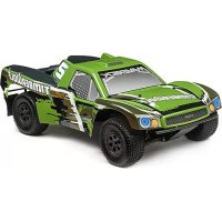
Components
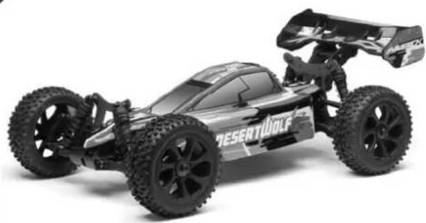
natural_image
Exterior view of a black and white toy car labeled 'DESERTWolf' (no additional text or symbols visible)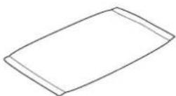
Parts Bag
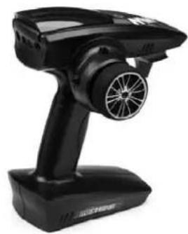
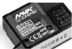
natural_image
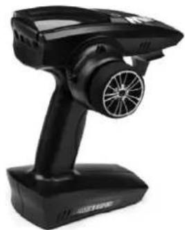
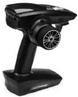
Black handheld electronic device with a circular fan and propeller, no visible text or symbolsTransmitter
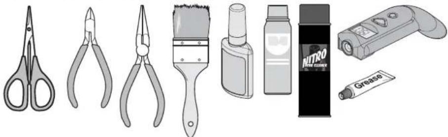
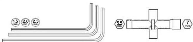
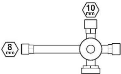
Included Tools
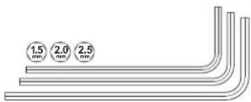
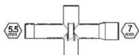
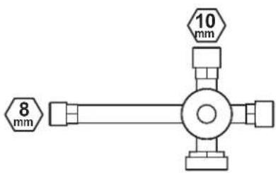
Recommended Tools
These tools are not included with the product but are recommended for use whilst working with this vehicle
natural_image
Illustration of various hair tools including scissors, pliers, brush, spray bottle, Nitro brush holder, and adhesive tube (no text or symbols)Scissors, Side Cutters, Needle Nose Pliers, Grease, Brush, CA Glue, Spray Lubricant, Cleaning Spray, Temperature Gun.
Items required for operation

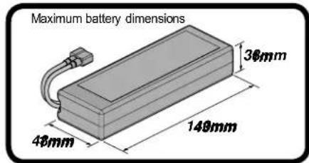
2-3 cell LiPo (7.4 to 11.1v) battery pack
For 2S or 3S LiPo packs we recommend a 25C rating or better. For 25C rated packs we recommend a minimum of 4000mAh. For 30C+ rated packs we recommend a minimum of 3500mAh. Do not use NiCd/NiMH battery chargers for LiPO batteries. If you do not use a special charger for LiPO batteries, they will be damaged. Using batteries with a lower C rating may result in damage to your batteries.


Caution
When using 3S LiPo batteries it is important to monitor the battery temperature. Battery temp should not exceed 60^ (140F)
Always disconnect the battery from the ESC when you are finished using your vehicle. The switch on the ESC controls the power that is delivered to the receiver and servos. The controller will always draw current when it is connected to the battery and will completely discharge batteries if they are connected for long durations. This may cause failure of your batteries.
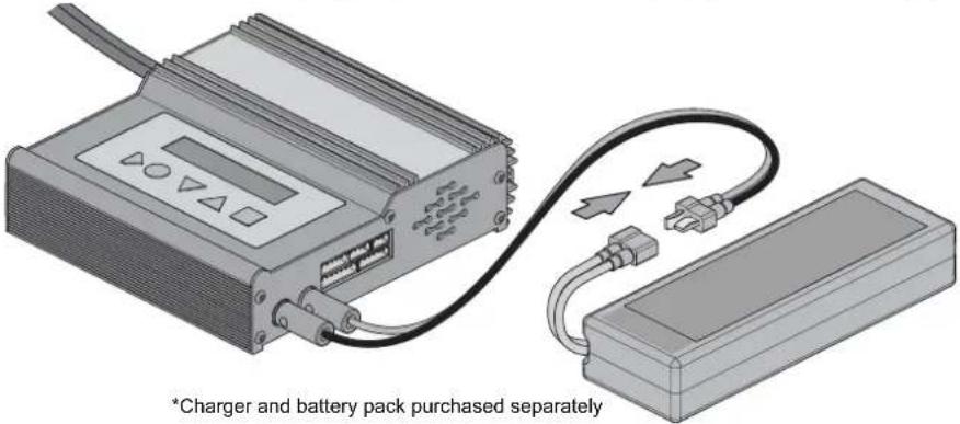
natural_image
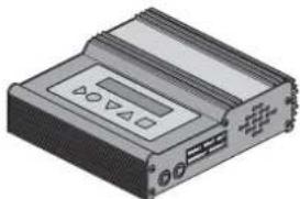
Illustration of a rectangular electronic device with ports and indicators (no text or symbols visible)LiPo Battery Charger

Caution
Do not use NiCd/NiMH battery chargers for LiPO batteries. If you do not use a special charger for LiPO batteries, they will be damaged.
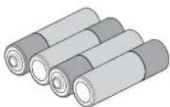
4 * AA Batteries for the Transmitter
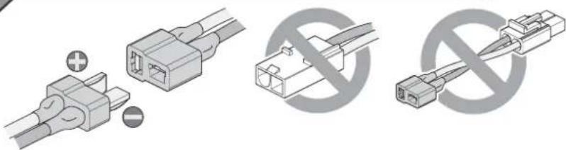
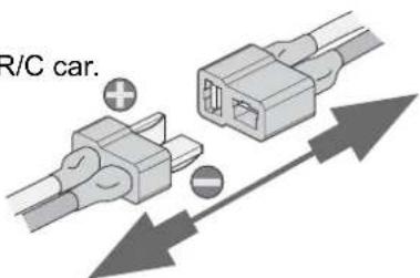
Battery Connector
natural_image
Diagram showing three types of electrical connectors: two connected to a terminal, one with a crossed-out symbol, and one without crossed-out symbol (no text or labels present)Poor quality battery connectors can be a roadblock to performance. Avoid the common "white plastic" connectors commonly seen on many battery packs. A fast brushless setup will draw many times the power that these connectors can safely handle. For this reason your Maverick ESC is equipped with a high capacity connector.
Charging the battery pack
Firstly you will need to charge the battery pack. Always use a charger that is rated for 2-3cell LiPo battery packs. Charging time for an empty battery pack will vary depending on the capabilities of the charger purchased, but could be as little as 30 minutes or up to 3 or 4 hours. Always follow the charger manufacturer's instructions in relation to charging your battery pack.
• Overcharging generates excessive heat and will damage the battery pack.
- Use the charger with adult supervision and do not leave unattended. Do not use the charger near water or when wet.
- Do not use the charger if the wire is frayed or worn. If the wire is frayed or worn a short circuit can cause a fire or burns.
- If you are unsure of the charge of the battery pack, use it in the vehicle until the vehicle slows, leave to cool and then recharge.
• Always remove the charger from the mains socket when not in use.
- It is recommended that a LiPo-Safe charging bag is used when charging your LiPo Battery pack.
Caution
Do not use NiCd/NiMH battery chargers for LiPO batteries. If you do not use a special charger for LiPO batteries, they will be damaged.
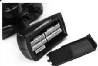
Installing the Transmitter Batteries
natural_image
Close-up of a black battery pack with visible internal compartments and a separate plastic housing (no text or symbols)Open the battery holding tray to expose the empty battery slots.
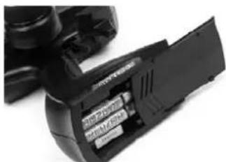
Insert 4 AA batteries into the marked spaces. Please note the correct direction of the batteries
natural_image
Close-up of a black DSLR camera module with visible internal components (no text or symbols)Incorrect battery insertion could damage the transmitter
2.4Ghz technology has done away with the need for long extendable aerials. The Aerial on your transmitter is located internally
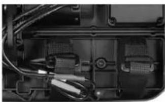
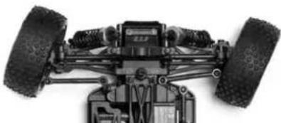
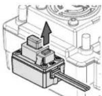
Installing the battery pack
natural_image
Close-up of a mechanical component with visible wiring and internal components (no text or symbols)You need to insert the battery pack in the open section for the battery. Use the chassis cut-out for corner wiring if needed. Use the straps provided to secure the battery in place.
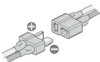
natural_image
Two connected electrical connectors with positive and negative terminals, no text or symbols visibleOnce fastened and secured please connect the battery plug into the speed controller plug noting correct polarity. Red to red, black to black.
Transmitter
Your Transmitter is an advanced controller designed for the beginner to be easy to use and tune. You will need to follow the steps below to ensure you prepare the controller correctly for use and understand the adjustment possibilities available.
The function switches on the transmitter
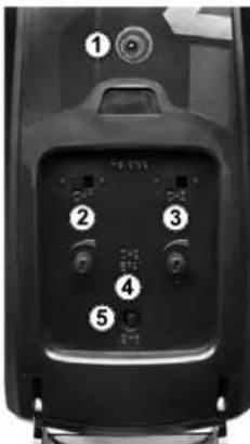
- Power LED
- Steering Reverse Switch
- Throttle Reverse Switch
- Throttle End Point Dial (low/high points)
- Bind Button
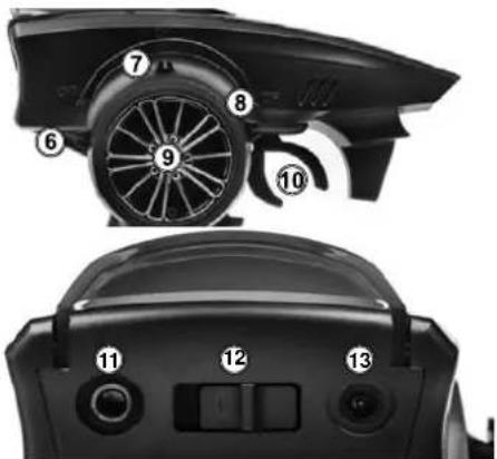
- Throttle Trim
- Steering Trim
- Steering Dual Rate (D/R) Switch
- Steering Control
- Throttle Trigger
- P.P.M. Output
- Power Switch
- Charging Port
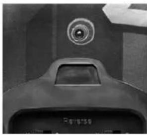
Throttle Trigger
- Pull the trigger to go forwards and speed up
- Push the trigger forward to brake
- Push again for reverse
Steering Wheel
Turn the steering wheel to the left or right to make the vehicle turn left or right
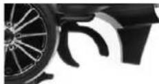
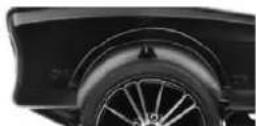
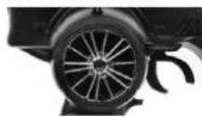
Steering Dual Rate (D/R) Reverse Switches
natural_image
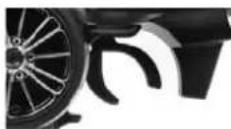
Close-up of a car wheel and dashboard components (no visible text or symbols)The dual rate settings adjust the maximum degree of movement from the servo.
Move the D/R lever down to increase or up to decrease the maximum steering angle.
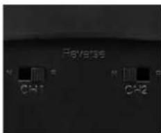
The Steering (ST) and Throttle (TH) reverse switches are set to "NOR" (Normal) as standard. To switch the direction of travel of either the steering or throttle move the switch to the "REV" (Reverse) position.
Throttle End Point Adjustment (EPA)
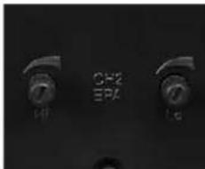
The throttle EPA allows you to adjust the maximum degree of movement of the throttle channel. "Hi" sets the EPA for the throttle direction, "Lo" sets the EPA for the brake direction. Turn the dial anti-clockwise to reduce or clockwise to increase the allowable degree of movement. When using this transmitter with an electric powered vehicle, set the end points to the maximum setting.
Trim Setup
If the steering is not straight with the transmitter on, make sure the trim dial is set to the central position and adjust the Servo horn on the car if needed. Then make fine adjustments with the steering trim whilst driving the vehicle.
Throttle Trim
Throttle neutral adjustments can be made by moving the throttle trim lever up for more throttle or down for more brake.
Steering Trim
Steering neutral adjustments can be made by moving the steering trim lever left or right.
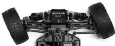
natural_image
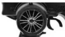
Top-down view of a small wheeled vehicle with two large tires and mounting feet (no visible text or symbols)If the wheels point left, turn clockwise
natural_image
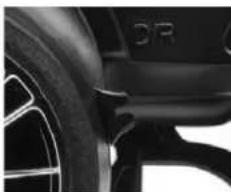
Top-down view of a heavy-duty vehicle chassis showing front wheel, suspension components, and suspension gear (no text or symbols visible)If they point straight no adjustment required.
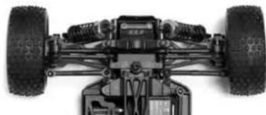
natural_image
Top-down view of a heavy-duty vehicle chassis with two tires and suspension components (no visible text or symbols)If wheels point right, turn anti-clockwise.
Turning on the power
Turn on transmitter first and then turn on receiver.
Turn on the transmitter switch and the LED battery indicator will light up.
Turn on the receiver. The automatic set-up of the factory set speed control should have been completed. If you experience any problems with the speed control settings refer to the Electronic Speed Control Section for correct setup information.
Power LED
natural_image
Close-up of a mechanical component with a circular top and handle, no visible text or symbolsThe Red LED will show if the installed AA batteries have sufficient charge.
The Red LED will flash and there will be an audible beep if the batteries need replacing.
Turning off the power
Turn off receiver first and then turn off transmitter.
If you switch off the transmitter first before the R/C car, you may lose control of the R/C car.
- Turn off the receiver switch.
- Turn off the transmitter switch.
- Disconnect the battery connector from the speed control connector.
Binding the Transmitter and Receiver
You may need to setup your transmitter to 'bind' with the receiver if you change to a new receiver or for any reason lose signal.
- Place the transmitter and the receiver close to each other (within one meter).
- Turn the power switch on the transmitter to the ON position.
- Press and hold the receiver setup button, then turn the power switch to the ON position.
• The receiver LED will flash quickly. Release the setup button after 1 second. - Press and hold the binding button on the transmitter for 1 second until the LED on the receiver is continuously lit.

This item is in accordance with Directive 1999/5EC. For the declaration of conformity visit: www.maverick-rc.com/ce Dieser Artikel entspricht der Richtlinie 1999/5/EC. Eine Konformitätserklärung finden Sie unter: www.maverick-rc.com/ce Cet article est conforme à la norme 1999/5/EC. Pour avoir Information sur conforme à la norme a.r.p visit : www.maverick-rc.com/ce Qesto articolo è conforme alla direttiva 1999/5/EC. Per la dichiarazione di conformità visitare il sito: www.maverick-rc.com/ce Este producto cumple con la Directiva 1995/5/EC. Para ver la declarazione di conformidad visitar: www.maverick-rc.com/ce
Electronic Speed Control Setup
MSC-29BL-80WP Features:
- Water-resistant* and dust-proof. The ESC has been designed to work in wet conditions.
a.*Please remove the cooling fan when using the ESC very wet conditions. b.*After using the ESC in wet conditions, please clean and dry it to avoid the oxidation to copper connectors
-
2-3S Capalable (for 3S you must change the standard 5V cooling fan to a 12V cooling fan, or supply the 5V cooling fan from the receiver 5-6V);
-
Compatible with sensorless brushless motor.
-
3 running modes ("Forward with brake" mode, "Forward/Backward with brake" mode, and "Rock Crawler" mode).
-
Proportional ABS brake function with 4 steps of maximum brake force adjustment, 8 steps of drag-brake force adjustment.
-
9 Punch modes from "Soft" to "Very aggressive" to be suitable for different chassis, tires and tracks.
-
Multiple protection features: Low voltage cut-off protection for Lipo or NiMH battery / Over-heat protection / Throttle signal loss protection / Motor blocked protection.
-
Easily programmed with the "SET" button on the ESC or with the LED Program Card.
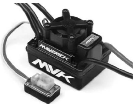
natural_image
Black and white photo of a Maverick motor with attached connector (no visible text or symbols)
Caution
This is an extremely powerful brushless motor system. We strongly recommend removing your tyres for your own safety and the safety of those around you before performing calibration and programming functions with this system. Please keep your hands, hair, and
loose clothing clear from the gear train and wheels of an armed high performance system.
Rubber tyres will "expand" to extreme size on a high speed vehicle. DO NOT hold the vehicle in the air and run it up to full throttle. Tyre failures at that speed can cause serious injury! Make sure your tires are securely glued to the rims and check them often! Always disconnect the battery from the ESC when you are finished using your vehicle.
The switch on the ESC controls the power that is delivered to the receiver and servos. The controller will always draw current when it is connected to the battery and will completely discharge batteries if they are connected or long durations. This may cause failure of your batteries.

Caution
Failure to follow these instructions can cause injury to yourself or others. You might also cause property damage or damage your kit.
As with any extremely high powered electric power system, the primary limitations to ultimate vehicle performance are the batteries and connectors. Use the best batteries and connectors you can find. The better the batteries, the more performance you will have! We do not recommend the use of low quality batteries referred to as "stick packs". Use of "stick packs" may result in personal injury or fire.
| Model MCS-29BL-80WP | ||
| Continuous Current 80A | ||
| Burst Current 540A | ||
| Resistance 0.0004 ohm | ||
| Application 1/10 scale On-Road and Off-Road | ||
| Motor Limit 2S LiPo /6 cell NiMh | On-Road: ≥ 5.5T | |
| Off-Road: ≤ 6000Kv | ||
| 3650 Size Motor | ||
| On-Road: ≥ 8.5T | ||
| Off-Road: ≤ 4000Kv | ||
| 3650/3660 Size Motor | ||
| Battery 4-9 cells NiMh or 2-3S LiPo1) For 4-6 cells NiMH or 2S Lipo: You needn't change the 5V cooling fan on the ESC;2) For 7-9 cells NiMH or 3S Lipo: You must change the original 5Vcooling fan to 12V cooling fan, or supply the 5V cooling fan from the receiver (5-6V); | ||
| Built-in BEC 6V/2A Linear | ||
| Program Port Multiplexed with cooling fan port | ||
| Motor Type Sensorless Brushless | ||
| Dimension 46*34*35mm | ||
| Weight 82g | ||
Electronic Speed Control Setup

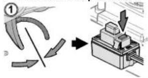
Important!
You must set up the ESC before running the first time. Initial setup, it is not required before every run.
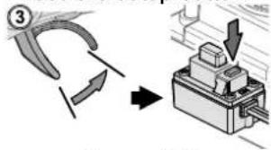
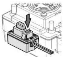
Hold down the setup button while turning on the ESC.
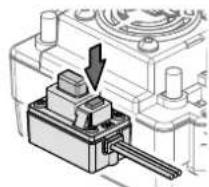
natural_image
Mechanical component diagram showing a lever mechanism with a downward arrow (no text or symbols)
LED

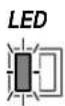
Release the setup button once the Red LED starts to flash
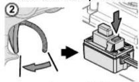
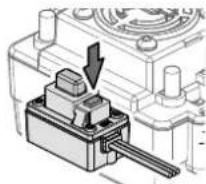
Leave the trigger in the neutral position.
Press the setup button.
LEDLED Green LED

fl ashes and a Beep sound comes from the motor.
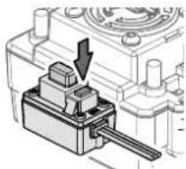
Move the trigger to full throttle.
Press the setup button.

Green LED
fl ashes twice.
Beeps twice from the motor.
Move the trigger to full brake.
Press the setup button.

Green LED
fl ashes three times. Beeps three times from the motor.
When the process has fi nished, motor control will be activated in 3 seconds
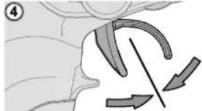
natural_image
Diagram of a biological structure with directional arrows indicating movement or force (no text or symbols)No LED Lighting

If the LED on the speed control does not work as described below, the speed control may not be setup correctly. Repeat the above process.
THE LED STATUS IN NORMAL RUNNING:
a) In normal use, if the throttle stick is in the neutral range, neither the red nor green LED will light.
b) The red LED lights when the car is run forward or backwards and will flash quickly when the car is braking.
c) The green LED lights when the throttle stick is moved to the top point of the forward zone (full throttle).
Programmable Mode Settings
| PROGRAM | PROGRAMMABLE VALUE | ||||||||
| 1 | 2 | 3 | 4 | 5 | 6 | ||||
| BASIC SETTINGS | |||||||||
| 1. Running Mode | Forward with Brake | Forward/Reverse with Brake | Rock Crawler | ||||||
| 2. Drag Brake Force 0% 5% | 10% | 20% | 40% | 60% | 80% | 100% | |||
| 3. Low Voltage Cut-off | Non-Protection | 2.6V/cell | 2.8V/cell | 3.0V/cell | 3.2V/cell | 3.4V/cell | |||
| 4. Start Mode (Punch) | Level 1 (Soft) | L2 | L3 | L4 | L5 | L6 | L7 | L8 | L9 (Very Aggressive) |
| ADVANCED SETTINGS | |||||||||
| 5. Max Brake Force 25% | 50% | 75% | 100% | ||||||
| 6. Max Reverse Force | 25% | 50% | 75% | 100% | |||||
| 7. Initial Brake Force | =Drag Brake Force | 0% | 20% | 40% | |||||
| 8. Neutral Range | 6% (Narrow) | 9% (Normal) | 12% (Wide) | ||||||
| 9. Timing | 0.00' | 3.75' | 7.50' | 11.25' | 15.00' | 18.75' | 22.50' | 26.25' | |
| 10. Overheat Protection | Enable | Disable | |||||||
Changing the setup
The ESC has a number of programmable modes that can be altered to suite a variety of functions. Each set of green LED flashes/beeps represents the programmable mode (1 flash = Running mode, 2 flashes = Drag brake force and 3 flashes = Auto-lipo settings etc..) and each set of red LED flashes/beeps represents that modes value. See the table below for all the programmable modes and their values. When you enter the setup mode you need to keep the button pressed until you enter the desired programme mode (green flashes/beeps). Once you reach that mode release the button and that will allow you to change the mode value (red flashes/beeps). You need to switch off the ESC to save the settings then re-do the process to change to a different mode or mode value setting. If you lose your way with setup then you can return the unit to default settings by turning on the ESC, keeping the transmitter in neutral and pressing the setup button for 3 seconds. Both red and green LED's will flash together 3 times to confirm this.

LEDLED


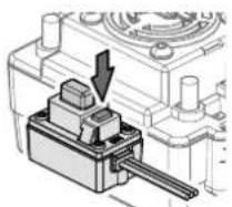
While switching on the ESC hold down the setup button. Continue to hold the setup button while the red LED fl ashes.
Continue to hold the setup button until the green LED starts to flash.
Red LED fl ashes for 4 seconds.
Green LED will begin to flash.
natural_image
Mechanical component diagram showing a lever mechanism with no visible text or symbolsLEDLED


LEDLED

3 green LED fl ashes represent the Low Voltage Cut-Off setting for example.
Each green LED flash represents the programmable mode number.
Release the setup button when you reach the desired mode. You are now in the program mode setting.

1 red LED flash represents the "No Protection" setting
Press the setup button to change the mode value. Each mode value will have different amounts of red LED fl ashes.
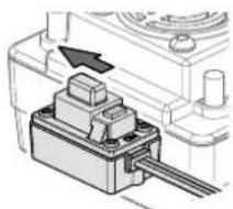
natural_image
Mechanical component diagram showing a piston-like assembly with an arrow indicating direction (no text or symbols present)In order to save the changes and settings you must switch off the ESC. When you next switch it back on it will have saved your new settings. To make further alterations you need to re-enter the mode values again.
Program Modes
| Running Modes | FWD w/Brake This mode is for forward and brake only |
| Fwd/Rev/Brake This mode offers forward, brake and reverse. Note, The reverse uses a soft start “Double Click” function which will only allow reverse to be activated once the motor has stopped moving forwards. | |
| Rock Crawler This mode allows the reverse function to happen immediately. Drag Brake should also be set to 100% to use this function for Rock Crawling. | |
| Drag Brake Force This allows the setting of an automatic drag brake when the throttle stick is returned to neutral, simulating the slight braking effect of a brushed motor while coasting. | |
| Low Voltage Cut-Off If the voltage of a LiPo battery pack is lower than the set threshold, the ESC will cut off the output power by 50%. The ESC will completely cut off the output power in 10 seconds. | |
Program Modes - Continued
| Start Mode (Punch) This mode selects the level of “punch” from a standing start.Level 1 is soft,right up to level 9 which is very aggressive. Please note, If levels 7-9 are selected, battery packs with low discharge rates or are poor quality will not be able to supply the needed power. It can also cause the motor to not run smoothly or tremble. | |
| Max Brake Force This mode sets the brakes force applied when the throttle is at full brake. A very large brake force may slow the car quickly but be aware it can also do damage to the cars drivetrain. | |
| Max Reverse Force This mode will set the reverse power applied by the ESC. The higher the value the quicker the reverse function will be. | |
| Initial Brake Force | This setting refers to the very first part of the braking zone. As default this is set to equal the Drag Brake Force which will give a smooth transition into braking. It can also be set higher to allow for a more aggressive braking function initially. |
| Neutral Range The neutral range is the area around the centre of the throttle movement. This mode will increase or decrease this area to suit your individual preference. | |
| Timing Different types of Brushless motors will react differently to timing values.Generally the higher the timing setting the more output power and performance you will gain. This is however balanced off with less run time, heat build up and efficiency of the system. We recommend the default timing as a good balance of performance and run time. | |
| Overheat Protection If the function is activated, the output power will be cut off when the temperature of the ESC is up to the factory threshold for more than 5 seconds.When the protection happens, the green LED will flash. | |
Resetting Default Values
The ESC can be reset to it default settings at any time. When the ESC is on (not in Setup Calibration or Programmable Settings modes) and the throttle is in the neutral position, hold the setup button for more than 3 seconds. The red and green LED's will flash at the same time 3 times to indicate that the defaults have been reset.
Driving
Driving an R/C car can be very difficult to master. We want you to have fun with your RC vehicle but please read the cautions detailed below followed by some basic tips to help you understand how to use your RC vehicle for the first time.
- Drive the vehicle in a very large space, especially until you get the feel of driving the vehicle.
- Do not drive on public streets or highways. This could cause serious accidents, personal injuries and/or property damage.
- Do not drive near members of the general public that could be placed at risk of injury.
- Do not drive in water or sand.
• 2.4Ghz radio frequency only functions in line of sight. If you drive behind a solid object or around a corner and lose sight of the vehicle you may lose control of the car.
If you hold full throttle on the transmitter, the vehicle will keep accelerating and run very fast. It is difficult to steer the vehicle running at high speeds. Drive the vehicle slowly by only pulling the throttle trigger a small amount to get used to how fast the car can go.
When the car is running towards the driver, the directions of the steering wheel are reversed.
Once you become conformable driving the vehicle, practice driving on a track with cones.
Keep practising until you feel comfortable with the steering, throttle and brake at low speeds.
Once you are feeling comfortable try the above using reverse.
When you have mastered the basics you will be able to drive at higher speeds in a more controlled fashion.
Allow the car to cool down for 15 minutes between each run
DISCONNECT THE BATTERY PACK AFTER USE!
Maintenance after driving
Proper maintenance is very important. Make sure to always perform appropriate maintenance after driving so that you can enjoy driving without problems next time.
Completely remove all dirt and debris from the vehicle, especially in the suspension, drive shafts and steering parts. Inspect each part and screws for loosening, missing parts or damages.
You should always make sure your wheels are tight and parts move freely after and before use.
Driving in wet conditions
This vehicle is designed to provide water protection for the on-board radio system components so it can be driven in wet conditions. The vehicle is not designed to be completely submerged in water. Driving in wet conditions will require additional maintenance.
Notes:
Never drive the vehicle in stormy conditions where lightning could be present. The transmitter is not waterproof, always keep it protected from rain and water.
Remove all water/mud and dry the vehicle completely after driving. Check the vehicle for trapped water in the tyres, transmission etc. Some metal parts like bearings and hinge pins will need lubrication after driving in wet or damp conditions. The electric motor is not designed to be submerged in water. If water gets inside it can reduce the life of the motor.
Most LiPo battery packs are not designed to operate in wet conditions. Consult the instruction manual or manufacturer for limitations.
After running in water, dry off any water from the ESC and connectors.
Trouble Shooting
Please read this section if you have any fault trying to operate the vehicle
| Problem Cause Remedy | ||
| The vehicle does not move Transmitter or receiver is off Turn on both the transmitter and receiver | ||
| The main battery is not charged enough | Charge the main battery | |
| The vehicle does not follow your driving inputs | Transmitter or receiver is off Turn on | both the transmitter and receiver |
| Transmitter reverse switches are set incorrectly | Check the reverse switch settings | |
| Transmitter End Point Adjustments (EPA) are set incorrectly | Check that your EPA Dials on your transmitter. | |
| Weak batteries in either the transmitter or the car | Replace batteries in the transmitter and recharge the main battery. | |
| The front and rear wheels rotate in opposing directions | Incorrect user differential placement | Insert the differential the correct way |
If you encounter any other fault whilst operating the vehicle please contact your local hobby shop or alternatively contact your local distributor.
natural_image
Black and white photo of a two-wheeled toy car labeled 'DESERTWOLF' with visible branding and suspension gear (no additional text or symbols)natural_image
Exterior view of a black and white toy car labeled 'DESERTWOLF' (no additional text or symbols visible)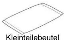

natural_image
Black handheld electronic device with a circular head and fan, no visible text or symbolsSender
natural_image
Illustration of various hair tools including scissors, pliers, brush, spray bottle, paint can, and spray tube (no text or labels)2-3 Lipo Zellen (7.4 to 11.1V) betreiben
natural_image
Illustration of a rectangular electronic device with ports and indicators (no text or symbols visible)LiPo Akkuladegerät

Warnhinweise
natural_image
Three types of electrical connectors shown: two connected to a terminal block and one with a crossed-out symbol (no text or labels present)natural_image
Close-up of a black electronic device with two partially visible modules (no text or symbols visible)natural_image
Close-up of a black DSLR camera module with visible internal components (no text or symbols)natural_image
Close-up of a mechanical or electronic component with visible wiring and connectors (no text or symbols)natural_image
Illustration of two connected electrical connectors with positive and negative terminals (no text or symbols)
natural_image
Close-up of a black electronic device's top panel with labeled buttons (no readable text or symbols beyond numbers)Gashebel
natural_image
Close-up of a car wheel and tire component (no visible text or symbols)natural_image
Top-down view of a small wheeled vehicle chassis with two tires and mounting feet (no visible text or symbols)natural_image
Top-down view of a heavy-duty vehicle chassis showing front wheel, suspension components, and battery pack (no text or symbols visible)natural_image
Top-down view of a two-wheeled vehicle chassis with visible tires and suspension components (no text or symbols)natural_image
Close-up of a mechanical component with a circular top and base (no visible text or symbols)natural_image
Diagram showing two connected electrical connectors with polarity indicators (no text or symbols)natural_image
Black and white photo of a robotic motor with visible branding (MAVERICK, MVK) and connector housing (no text or symbols on main body)
Warnhinweise
natural_image
Mechanical component diagram showing a lever mechanism with a downward arrow (no text or symbols)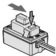
natural_image
Diagram showing a curved arrow and directional arrows in a biological or anatomical context (no text or symbols)LEDLEDLED
natural_image
Mechanical assembly diagram showing a lever mechanism with no visible text or symbolsLEDLED


natural_image
Black and white photo of a two-wheeled toy car with visible tires, motors, and branding (no text-heavy elements)natural_image
Exterior view of a black and white toy car labeled 'DESERTI WOLF' (no additional text or symbols visible)
natural_image
Black handheld electronic device with a circular head and base, no visible text or symbolsEmetteur
Outils inclus
Outils recommandés
natural_image
Illustration of various hair tools including scissors, pliers, paintbrush, spray bottle, and spray can (no text or labels)natural_image
Illustration of a rectangular electronic device with ports and buttons (no text or symbols visible)natural_image
Three types of electrical connectors shown: two connected to a power outlet, one without a prohibition symbol, and one with a crossed-out line (no text or labels present)natural_image
Close-up of a black electronic device with two partially visible modules, no text or symbols visible.natural_image
Close-up of a black DSLR camera module with visible internal components (no text or symbols)natural_image
Interior view of a laptop case showing internal components and wiring (no visible text or symbols)natural_image
Illustration of two connected electrical connectors with positive and negative terminals (no text or symbols)natural_image
Close-up of a car wheel and tire component (no visible text or symbols)natural_image
Top-down view of a black-and-white photo of a toy vehicle with two large tires and mounting feet (no visible text or symbols)natural_image
Top-down view of a two-wheeled vehicle chassis showing front wheel, suspension gear, and chassis components (no text or symbols visible)natural_image
Top-down view of a heavy-duty vehicle chassis with two tires and suspension components (no visible text or symbols)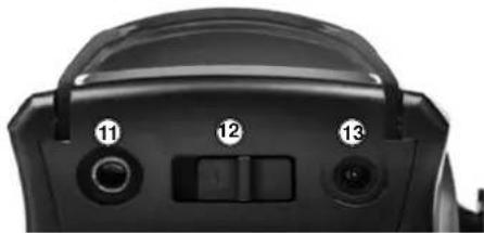
natural_image
Close-up of a black camera lens with three labeled buttons (11, 12, 13) and a central adjustment knob (no text or symbols beyond labels)Roue directrice
natural_image
Top-down view of a toy car chassis with two tires and suspension components (no visible text or symbols)Mise en marche
natural_image
Close-up of a mechanical component with a circular top and central slot, no visible text or symbolsnatural_image
Diagram showing two connected electrical connectors with polarity indicators (no text or symbols)natural_image
Black and white photo of a robotic control unit labeled 'MAVERICK' with visible wiring and a small connector (no text beyond branding)
Précautions
LEDLED LED Verte


natural_image
Diagram showing a curved mechanical component with directional arrows indicating motion or force (no text or symbols)
AUCUNE LED allumée
natural_image
Mechanical component diagram showing a piston and shaft assembly with an arrow indicating direction (no text or symbols)natural_image
Black and white photo of a two-wheeled toy car with visible tires, wheels, and branding (no text-heavy elements)natural_image
Black and white photo of a toy car with visible tires and front suspension, no text or symbols on body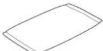
Bolsa de piezas
natural_image
Black handheld electronic device with a circular fan and base mount (no visible text or symbols)Transmisor
natural_image
Illustration of various hair tools including scissors, pliers, brush, spray bottle, Nitro powder can, and cotton product (no text or symbols)natural_image
Illustration of a rectangular electronic device with ports and indicators (no text or symbols visible)natural_image
Diagram showing three types of electrical connectors: plug, socket, and switch (no text or symbols present)natural_image
Black plastic battery pack with two partially open batteries, no visible text or symbolsnatural_image
Close-up of a black DSLR camera module with visible internal components (no text or symbols)natural_image
Close-up of a mechanical or electronic component with visible wiring and connectors (no text or symbols)natural_image
Illustration of two connected electrical connectors with positive and negative terminals (no text or symbols)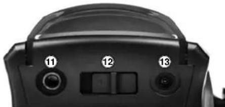
natural_image
Close-up of a black camera lens with adjustment knobs and control buttons (no text or symbols visible)natural_image
Close-up of a car wheel and tire component (no visible text or symbols)natural_image
Top-down view of a two-wheeled vehicle chassis with visible tires and suspension (no text or symbols)natural_image
Top-down view of a heavy-duty vehicle chassis showing front wheel, suspension components, and suspension gear (no text or symbols visible)natural_image
Top-down view of a heavy-duty toy vehicle showing front wheel, suspension, and chassis components (no visible text or symbols)natural_image
Close-up of a black mechanical component with a circular top and side ports (no visible text or symbols)natural_image
Diagram showing two connected electrical connectors with directional arrows indicating connection (no text or symbols)natural_image
Black MAVK motor with attached wiring and a small connector (no visible text or symbols)
Advertencia
LEDLE


natural_image
Illustration of a medical procedure showing hand placement and directional arrows (no text or symbols)
natural_image
Black and white photo of a desertwolf toy with visible branding and wheels (no text or symbols on the vehicle itself)MAVERICK
Notes, Notizen, Notas
MAVERICK
Notes, Notizen, Notas