BAKER GA 930 - Fridge GRAM - Free user manual and instructions
Find the device manual for free BAKER GA 930 GRAM in PDF.
Download the instructions for your Fridge in PDF format for free! Find your manual BAKER GA 930 - GRAM and take your electronic device back in hand. On this page are published all the documents necessary for the use of your device. BAKER GA 930 by GRAM.
USER MANUAL BAKER GA 930 GRAM
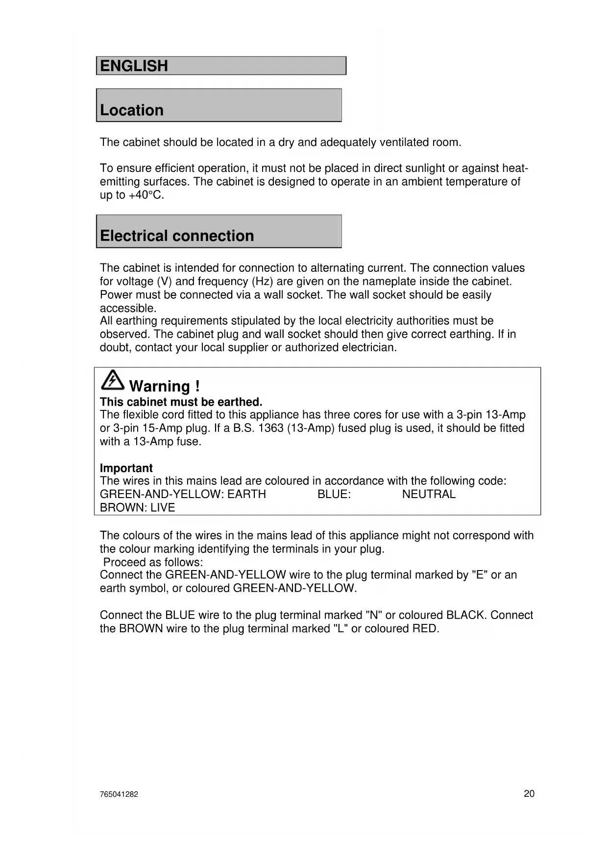
BROWN: LIVE The colours of the wires in the mains lead of this appliance might not correspond with the colour marking identifying the terminals in your plug. Proceed as follows: Connect the GREEN-AND-YELLOW wire to the plug terminal marked by "E" or an earth symbol, or coloured GREEN-AND-YELLOW. Connect the BLUE wire to the plug terminal marked "N" or coloured BLACK. Connect the BROWN wire to the plug terminal marked "L" or coloured RED.765041282 21
Starting up + key Program selection/stop - key
Servicing: Make sure the appliance is switched off at the socket before service is performed on electrical parts. It is not sufficient to switch off the cabinet by the main switch as there will still be voltage to some electrical parts of the cabinet. Settings to be made before use: The following settings are to be made before the cabinet is taken into use: the season, the time setting, the weekday, the year, and choice of language. These settings are quite simple to do, and should only be done once. There are exceptions in certain situations. If the cabinet is without power supply due to power failure, or if it is switched off at the mains for more than 24 hours, the settings which may have been done, will be lost. The personal settings of the various programmes will be lost, too. The switch is located behind the control panel. To access the switch, open the panel by pulling its left-hand side outward. On switching the cabinet on, the green chilling lamp and the P key light up and "G107" is shown in the display for 10 seconds, then "OFF" is shown. The cabinet is now operating in stand-by mode.765041282 22
In the event of power failure, the controller will return to factory setting, which is german, and all personal programmes will be reset. Season, time, weekday, year and language setting: Display information can be shown in different languages, as shown below. To set the season, the time, the weekday, the year and language, proceed as follows:
- Push the P key several times until "End" and the process end time is displayed.
- Keep the P key pushed.
- Now push the + key shortly, and release both buttons simultaneously.
- The display now alternates between "Uint" and "SAES".
- Push the + or the – key to choose the right season. ("Uint" = winter time, "Sunn" = summer time).
- Push the P key to scroll to the next parameter. (See below).
- Use the + or – keys to set the selected parameters.
12.00 tinE Setting the clock between 0.00 and 23.50 hrs.
Display mode during operation: The display mode during operation depends on the choice of programme: Chilling: The display alternates between the current cabinet temperature, followed by a "C", and the remaining process time. The chilling indicator LED lights up. Storage: The current cabinet temperature followed by a "C" is displayed. The storage indicator LED lights up. Retarding: The display alternates between the current cabinet temperature, followed by a "C", and the relative humidity followed by an "F". The retarding indicator LED lights up. Proving: The display alternates between the current cabinet temperature, followed by a "C", and the relative humidity followed by an "F". The proving indicator LED lights up.
Setting program parameters When the cabinet is in stand-by mode, pressing + or – toggles between the 5 programs shown on the display: Pr1, Pr2, Pr3, Pr4 and Pr5. The various settings for the selected program can be accessed by repeatedly pressing P. The setting for any selected parameter can be altered by pressing + or –. Press P again to continue scrolling through the program parameters. When altered, settings are automatically saved. Program parameters:
Display indication Range LED indication Description Pr1 Pr 1 to Pr 5 - Programme selection. -15C Cool -25 °C to +5 °C Chilling Temperature setpoint
Starting and stopping the program The various steps in a control program can be started manually and used individually. In other words, the cabinet can be used for storage, thawing or proving indefinitely. With correct programming, some of the programs can be combined. The following combinations are possible:
- Chilling followed by indefinite storage.
- Chilling followed by storage and then indefinite defrosting.
- Complete program with chilling, storage, thawing and indefinite proving.
Example: Chilling and storage A program comprising rapid freezing followed by storage is required.
- Press + or –. The display shows Pr1, Pr2, Pr3, Pr4 and Pr5 in turn.
- When the required program is displayed, press P once.
- The green chilling lamp lights up. "ChiL" and the temperature setting are shown in turn in the display.
- Press + or – until the required chilling temperature is shown in the display.
- Again, press P once.
- "ChiL" and the chilling time are now shown in turn in the display.
- Press + or – to set the required chilling time.
- Again, press P once.
- The display now shows the text "Stor" and the storage temperature setting in turn.
- Press + or – to set the required storage temperature.
- Press P repeatedly until the first green lamp lights up again.
- Press S until "Strt" is shown in the display and then release it.
- Stop the program again by pressing P for 3 seconds.765041282 25
Program running Chilling and storage Firstly, cabinet temperature is controlled for the set period of time at the set chilling temperature. Cabinet temperature is then controlled at the set storage temperature. Storage Cabinet temperature is controlled at the set storage temperature. Proving Cabinet temperature and relative humidity are controlled at the defrost settings. Chilling, storage, retarding To allow the controls to calculate the storage time, it is necessary to set the chilling time, the defrost time, and the time of program end. Example of program for chilling, storage and defrosting Chilling is set to last 2 hours at -15°C. Storage temperature is set to -4°C, and defrosting is set to last 5 hours at 2°C. The program is set to end at 04:00 the following day. In the example, the program is started at 14:45. The program switches from chilling to storage at 16:45. The program switches from storage to retarding at 23:00. The calculated storage time is thus 6 hours and 15 minutes. Firstly, cabinet temperature is controlled for the set period of time at the set chilling temperature. Cabinet temperature is then controlled for the calculated period of time at the set storage temperature. The cabinet is heated when the program switches from storage to retarding. During retarding, the relative air humidity is continuously controlled at the set value.
14:45 18:45 23:00 04:00 Temperature curve during chilling, storage and retarding.765041282 26
Programming: Chilling and subsequent storage
- Press P repeatedly until "Stor" is shown in the display (the second green lamp lights up).
- Set the required storage temperature by pressing + or –.
- Press P repeatedly until "ChiL" is shown in the display (the first green lamp lights up).
- Set the required chilling temperature by pressing + or –.
- Set the required chilling time by pressing + or –.
- Press and hold S for 3 seconds to start the process.
Temperature curve during chilling and storage. Storage
- Press P repeatedly until "Stor" is shown in the display (the second green lamp lights up).
- Set the required storage temperature by pressing + or –.
- Press and hold S for 3 seconds to start the process. -4,5
Temperature curve during storage.765041282 27
- Press P repeatedly until "rEtA" is shown in the display (the yellow lamp lights up).
- Set the required temperature by pressing + or –.
- Set the relative humidity required during retarding by pressing + or –.
- Press and hold S for 3 seconds to start the process.
2,5 Temperature curve for retarding. Proving
- Press P repeatedly until "Pro" is shown in the display (the red lamp lights up).
- Set the required proving temperature by pressing + or –.
- Set the relative humidity required during proving by pressing + or –.
- Press and hold S for 3 seconds to start the process.
Temperature curve for proving.765041282 28
Chilling, storage and constant retarding:
- Press P once. "ChiL" is shown in the display (the first green lamp lights up).
- Set the required chilling temperature by pressing + or –.
- Set the required chilling time by pressing + or –.
- Press P once. "Stor" is shown in the display (the second green lamp lights up).
- Set storage temperature by pressing + or –.
- Press P once. "rEtA" is shown in the display (the yellow lamp lights up).
- Set the required retarding temperature by pressing + or –.
- Set the required relative humidity by pressing + or –.
- Set the required retarding time by pressing + or –.
- Press P once. "Pro" is shown in the display (the red lamp lights up).
- Press P three times.
- Set the required proving time (hours:minutes) by pressing + or –.
- Press P once. "End" is shown in the display (the red lamp remains lit).
- Set the process end time by pressing + or –.
- Set the process end day by pressing + or –.
- Press and hold S for 3 seconds to start the process.
Temperature curve for chilling, storage and constant retarding.765041282 29 Complete proving program
- Press P once. "ChiL" is shown in the display (the first green lamp lights up).
- Set the required chilling temperature by pressing + or –.
- Set the required chilling time by pressing + or –.
- Press P once. "Stor" is shown in the display (the second green lamp lights up).
- Set the required storage temperature by pressing + or –.
- Press P once. "rEtA" is shown in the display (the yellow lamp lights up).
- Set the required retarding temperature by pressing + or –.
- Set the required relative humidity by pressing + or –.
- Set the required retarding time by pressing + or –.
- Press P once. "Pro" is shown in the display (the red lamp lights up).
- Set the required proving temperature by pressing + or –.
- Set the relative humidity required during proving by pressing + or –.
- Set the required proving time by pressing + or –.
- Press P once. "End" is shown in the display (the red lamp lights up).
- Set the process end time by pressing + or –.
- Set the process end day by pressing + or –.
- Press and hold S for 3 seconds to start the process.
After the completion of the fermentation program An extra program is built in which begins to cool down the products after the end of the fermentation process. This stops the fermentation in the products. Mode of operation and signals The time after the completion of the program is called tS. When the time tS has expired, the program section tA begins. The default value of tS is 10 minutes, but it can be regulated from 0 to 30 minutes. When the time is set to 0 minutes, the tS program is not active, and the device continues the fermentation program without pause. This corresponds to older program versions, such as G 108. When the tS program is active, the red LED lamp flashes. This is to warn the user of the extended time for the fermentation process. When program section tA begins, the cooling system begins to cool the products, and brings the temperature down to the standard value of +2°C. Now it is the yellow LED lamp that flashes, to warn that the products have been through both a normal fermentation process and the extra time tS. The yellow LED lamp continues to flash until the device is stopped completely. This is done by pressing the P button. Interruption of the programs tS and tA While the program is engaged in either the extended time tS or the actual cooling phase tA, the user can choose to press either the P or the S button. Pressing the P button will stop the device completely. If the S button is pressed, the device will return to the GA program and will continue to run this. If the S button is pressed during the extended time or the cooling phase, the red lamp will glow constantly, and the other lamps will be turned off. Setting tS and tA The settings of the two new values can be adjusted via the hidden service menu of the control system. Interrupting the automatic program before the program concludes and tS begins If the user returns to the device before the conclusion of the complete program, the user can choose to push the S button to cancel the complete program. The program will now continue its normal functioning with the GA program. For this to be done, the GA program must have entered the last quarter of its cycle. Information on the time of completion is removed through this choice, and only the temperature and humidity are shown, alternately. The two green lamps and the yellow lamp are also turned off.765041282 31
01 If this code is displayed, it means that the cabinet temperature sensor has a short circuit. In the meantime, the cabinet itself will try to maintain the set temperature. The sensor must be replaced. Request service assistance. 02 If this code is displayed, it means that the cabinet temperature sensor has been broken. In the meantime, the cabinet itself will try to maintain the set temperature. The sensor must be replaced. Request service assistance. 03 If this code is displayed, it means that the evaporator temperature sensor has a short circuit. It means that defrosting of the evaporator will be interrupted. The sensor must be replaced. Request service assistance. 04 If this code is displayed, it means that the evaporator temperature sensor has been broken. It means that defrosting of the evaporator will be interrupted. The sensor must be replaced. Request service assistance. 07 If this code is displayed, it means that the humidity sensor has a short circuit. It means that humidifying will be interrupted. The sensor must be replaced. Request service assistance. 08 If this code is displayed, it means that the humidity sensor has been broken. It means that humidifying will be interrupted. The sensor must be replaced. Request service assistance. 23 Temperature alarm. The temperature monitoring is factory-set to +/- 10°C relative to the setpoint. The alarm is triggered, if the upper or lower limit is exceeded. 40 Steam generator system alarm. This means that an error has occurred in the steam generator system. Request service assistance.
By pushing the P key, it is possible to view the errors that may have occurred. If several errors have appeared, they are shown as F1, F2, etc., - the display alternates between this indication and the actual error code. (Only when the cabinet is in stand-by mode). "clr" is displayed to indicate, if you want to confirm / ignore the error(s). To confirm / ignore the errors, push the + key. To retain the error indications, push the – key.
During power failure, the control unit remembers all entered program settings and the clock continues to run. The program therefore proceeds as if nothing had happened.765041282 32
Defrost water and water flushed from the humidifier are led away through a pipe on the rear of the cabinet. A water seal must be installed between cabinet and drain.
To provide steam during proving, the humidifier must be connected to a water supply. Please note the following: The electrical conductivity of the water must be in the range: 50-800 µS/cm. The temperature of the water must not exceed 60°C. The water pressure must be in the range 1-10 bar. A shut-off valve, a check valve, and a filter if necessary, must be fitted to the supply pipe. Steam humidifier
The cabinet is equipped with a humidifier that provides steam during proving. The humidifier consists of a water tank heated by electrodes. From the tank, steam is led into the cabinet through a pipe. The tank is automatically filled from the water supply. The tank can be flushed by switching the cabinet off at the main switch and then switching it on again. In addition, the system is automatically flushed regularly depending on water quality. For further information on servicing and maintaining the humidifier, please consult the "Service and operation manual". For maintenance of the humidifier, request service assistance.765041282 33
Door closing mechanism The door is equipped with a self-closing system. The door can be opened by using the foot pedal. This leaves both hands free when filling the cabinet. Cleaning Always disconnect the cabinet at the mains before cleaning. Do not flush compressor compartment and evaporator with water as this may cause short-circuits in the electrical system. The cabinet should be cleaned internally with a mild soap solution at suitable intervals and checked thoroughly before it is put into operation again. For the external maintenance – use stainless steel polish. Do not use cleansing agents containing chlorine or compounds of chlorine as well as other corrosive means, as they might cause corrosion to the stainless panels inside the cabinet and the evaporator system. The compressor compartment and in particular the condenser must be kept free from dust and dirt. This is best done with a vacuum cleaner and a brush. The air filters on the condenser and the front panel can be removed and cleaned in a dishwasher at max. 50°C.
Service If the cabinet is to operate under optimum conditions, it is recommended to regularly have it serviced by qualified personnel. It is advisable to let the cabinet enter into a maintenance plan. The refrigerating system and the hermetically sealed compressor require no maintainance. However the condenser and air filter requires regular cleaning. If refrigeration fails, first look to see whether the cabinet has been unintentionally switched off, or whether a fuse has blown. If the cause of failure cannot be found, contact your supplier quoting TYPE, PART NO and SER. NO of the cabinet. This information can be found on the nameplate.765041282 34
Placement of the nameplate: Made in Denmark Type Part no. Serie no. prod. no. Climate class Volt Watt Watt Refrigerant