
KLE 1002 - Boiler AEG - Free user manual and instructions
Find the device manual for free KLE 1002 AEG in PDF.



| Product type | Wall-mounted electric convector |
| Brand | AEG |
| Model | KLE 1002 |
| Connection power | 1 kW |
| Power supply | 230/240 V, 1/N ~ |
| Dimensions (W × H × D) | 1110 × 250 × 100 mm |
| Weight | 5.9 kg |
| Protection rating (IP) | IP24 |
| Protection class | II |
| Temperature range | 10 to 30 °C |
| Frost protection | Activated below 7 °C |
| Operating modes | Comfort, Reduced, Automatic, Off |
| Reduction in Reduced mode | Approximately 3.5 °C below set temperature |
| Heating indicator | Lights up when heating is on |
| Pilot wire | Yes (black wire) for external control |
| Maintenance | Clean when cold with standard products, avoid abrasives; vacuum ventilation grilles |
| Safety | Safety limiter against overheating; do not cover; minimum distance to objects (not specified, estimate 50 cm) |
| Installation | Wall mounting, distance from floor ≥ 210 mm (for KLE 1002), do not install under a wall socket |
| Environment and recycling | Dispose of in accordance with national regulations |
Frequently Asked Questions - KLE 1002 AEG
User questions about KLE 1002 AEG
0 question about this device. Answer the ones you know or ask your own.
Ask a new question about this device
Download the instructions for your Boiler in PDF format for free! Find your manual KLE 1002 - AEG and take your electronic device back in hand. On this page are published all the documents necessary for the use of your device. KLE 1002 by AEG.
USER MANUAL KLE 1002 AEG
Plinth convector heater
Operation and installation 11
- General information 11
- Safety 12
- Appliance description 13
- Settings 13
- Cleaning, care and maintenance 14
- Troubleshooting 14
INSTALLATION
- Safety 14
- Appliance description 14
- Installation 14
- Commissioning 16
- Shutdown 16
- Troubleshooting 16
- Specification 16
GUARANTEE
ENVIRONMENT AND RECYCLING
SPECIAL INFORMATION
- Keep children under the age of 3 away from the appliance if constant supervision cannot be guaranteed. Children from the age of 3 to 8 may switch the appliance on and off, provided they are supervised or have been instructed in the safe operation of the appliance and understand any risks that may result there from. This is subject to the appliance having been installed as described.
Children from the age of 3 to 8 must not plug the power cable into its socket nor regulate the appliance.
The appliance may be used by children aged 8 and up and persons with reduced physical, sensory or mental capabilities or a lack of experience and know-how, provided that they are supervised or they have been instructed on how to use the appliance safely and have understood the resulting risks. Children must never play with the appliance. Children must never clean the appliance or perform user maintenance unless they are supervised.
- If operated on a time switch, the appliance may continue to heat the room unchecked. Ensure constant supervision if the appliance is used in a small room and the persons within that room cannot leave the room on their own.
- Parts of the appliance can get very hot and may cause burns.
Particular caution is advised when children or vulnerable persons are present.
- Never cover the appliance.
- Never install the appliance directly below a wall socket.
- Install the appliance in such a way that the control equipment cannot be touched by a person in the bath or shower. In the case of a permanent connection, the appliance must be able to be separated from the power supply by an isolator that disconnects all poles with at least 3 mm contact separation. In the event of damage to the power cable this must always be replaced by a qualified electrician authorised by the manufacturer, using original spare parts.
- Secure the appliance as described in chapter "Installation / Installation".
OPERATION
1. General information
The chapters "Special Information" and "Operation" are intended for both the user and qualified contractors.
The chapter "Installation" is intended for qualified contractors.
Note
Read these instructions carefully before using the appliance and retain them for future reference.
Pass on the instructions to a new user if required.
1.1 Safety instructions
1.1.1 Structure of safety instructions

KEYWORD Type of risk
Here, possible consequences are listed that may result from failure to observe the safety instructions.
» Steps to prevent the risk are listed.
1.1.2 Symbols, type of risk
| Symbol Type of risk | |
| ! | Injury |
| Electrocution | |
| Burns (burns, scalding) | |
1.1.3 Keywords
| KEYWORD Meaning |
| DANGER Failure to observe this information will result in serious injury or death. |
| WARNING Failure to observe this information may result in serious injury or death. |
| CAUTION Failure to observe this information may result in non-serious or minor injury. |
1.2 Other symbols in this documentation

Note
General information is identified by the adjacent symbol.
Read these texts carefully.
| Symbol Meaning | |
| ! | Material losses (appliance damage, consequential losses and environ-mental pollution) |
| Appliance disposal | |
» This symbol indicates that you have to do something. The action you need to take is described step by step.
1.3 Information on the appliance
| Symbol Meaning | |
| Never cover the appliance | |
1.4 Units of measurement

Note
All measurements are given in mm unless stated otherwise.
2. Safety
2.1 Intended use
This appliance is designed to heat living areas.
This appliance is intended for domestic use. It can be used safely by untrained persons. The appliance can also be used in a non-domestic environment, e.g. in a small business, as long as it is used in the same way.
Any other use beyond that described shall be deemed inappropriate. Observation of these instructions and of instructions for any accessories used is also part of the correct use of this appliance.
2.2 General safety instructions

WARNING Burns
Never operate this appliance...
- if the minimum clearances to adjacent object surfaces such as furniture, net curtains, curtains, textiles or other flammable materials are not maintained. in rooms where the appliance is at risk of fire or explosion as a result of chemicals, dust, gases or vapours. Ventilate the room sufficiently before heating. in the direct proximity of electrical cables or receptacles that carry or contain flammable or explosive materials. if an appliance component is damaged, the appliance has fallen over or already has a fault. outdoors.

WARNING Burns
Never place any flammable, combustible or insulating objects or materials on the appliance or in direct proximity to it.

WARNING Burns
Ensure that no foreign bodies enter the ventilation or extract air apertures. This could result in electric shock, fire or damage to the appliance.

WARNING Burns
To prevent fires ensure that the air inlets and outlets are never blocked.
Never position the appliance on soft surfaces such as a bed, as this could result in the apertures becoming blocked.

WARNING Burns
If operated on a time switch, the appliance may continue to heat the room unchecked. Ensure constant supervision if the appliance is used in a small room and the persons within that room cannot leave the room on their own.

WARNING Injury
Keep children under the age of 3 away from the appliance if constant supervision cannot be guaranteed. Children from the age of 3 to 8 may switch the appliance on and off, provided they are supervised or have been instructed in the safe operation of the appliance and understand any risks that may result there from. This is subject to the appliance having been installed as described. Children from the age of 3 to 8 must not plug the power cable into its socket or regulate the appliance. The appliance may be used by children aged 8 and up and persons with reduced physical, sensory or mental capabilities or a lack of experience and know-how, provided that they are supervised or they have been instructed on how to use the appliance safely and have understood the resulting risks. Children must never play with the appliance. Children must never clean the appliance or perform user maintenance unless they are supervised.

CAUTION Burns
Parts of the appliance can get very hot and may cause burns. Particular caution is advised when children or vulnerable persons are present.

Material losses
Never cover the appliance.
Never stand on the appliance.
2.3 CE designation
The CE designation shows that the appliance meets all essential requirements according to the:
Electromagnetic Compatibility Directive Low Voltage Directive
2.4 Test symbols
See type plate on the appliance.
3. Appliance description
The appliance is a wall mounted electric direct heater.
The appliance is suitable for use as a standalone heating system, or can be used between seasons and as a booster heater in smaller rooms, such as hobby and guest rooms.
The air in the appliance is heated by a heating element and expelled via natural convection through the air outlet grille at the top. Cooler indoor air is drawn in through openings on the underside of the appliance.
The external casing of the appliance is made from stove enamelled sheet steel.
The operating unit and temperature sensor can be found at the back of the appliance.
The appliance has a high limit safety cut-out that switches it off when there is a risk of overheating.
4. Settings
4.1 Operating unit
The operating unit can be found at the back of the appliance, at the top right, and can be operated from above.
1 Heating indicator
2 Sliding switch 3 Temperature selector
Use the sliding switch to select the desired operating mode or to switch the appliance off.
Use the temperature control knob to set the room temperature (10 - 30°C)
The heating indicator lights up when the appliance is heating. When the set room temperature has been reached, the heating indicator goes off.
4.2 Operating modes
| Symbol Operating mode | |
| Appliance | switched off |
| Comfort | mode |
| Setback | mode |
| Program | med operation |
| Frost protection | |
4.2.1 Comfort mode
In comfort mode, the appliance switches off automatically as soon as the required room temperature has been reached. By heating intermittently, the appliance maintains a constant room temperature.
To select comfort mode, proceed as follows:
» Set the sliding switch to comfort mode. » To select the desired room temperature, turn the temperature control knob to the left.

Note
To achieve the same temperature in two different rooms, the setting on the temperature control knob might be different on each appliance.
The same is true if there is more than one appliance in a single room.

Note
If a window is open, the room temperature regulator may not turn the appliance off.
Turn the appliance off while you are airing the room, to avoid excessive electricity consumption.
4.2.2 Setback mode
In setback mode, the appliance automatically reduces the room temperature selected in comfort mode by about 3.5°C.
If you are leaving the room for more than 2 hours, use setback mode.
Set the sliding switch to setback mode. To select the desired room temperature, turn the temperature control knob to the left.
4.2.3 Programmed operation
You can connect the appliance to an optional control unit via the appliance's integral control cable (see chapter "Installation / Electrical connection").
Depending on the setting of the control unit, the appliance operates in comfort, setback or frost protection mode at specific times of the day.
If you set the sliding switch to programmed operation with no control device connected, the appliance will operate in comfort mode.
4.2.4 Frost protection
In frost protection mode, the temperature controller turns the appliance on automatically as soon as the room temperature falls below 7°C.
4.3 Restricting the control switches
At the rear of the operating unit there are 3 pins with which you can fix or restrict the settings of the sliding switch and temperature control knob.
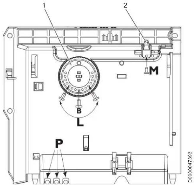
1 Temperature selector 2 Sliding switch P Pin holder B Fixing the temperature control knob to a specific temperature L. Restricting the temperature control knob to a specific temperature range M Fixing the sliding switch to a specific operating mode
5. Cleaning, care and maintenance
The appliance contains no user serviceable parts.
Clean the appliance when cold with ordinary cleaning products. Avoid abrasive or corrosive cleaning products. If a pale brownish discoloration appears on the appliance casing, wipe it off with a damp cloth. Regularly clean the upper and lower ventilation grilles of the appliance with a vacuum cleaner.
Material losses Never spray cleaning spray into the air slot.
6. Troubleshooting
| Problem Cause Remedy | ||
| The appli- ance does not heat up. | The temperature is set too low. | Check the temperature set on the appliance. |
| The power supply has been interrupted. | Check the MCB/fuse in your fuse box/distribution panel. | |
| The appliance has overheated. The high limit safety cut-out has switched the appliance off. | Remedy the cause, such as a covered or dirty air outlet or intake. After a few minutes of cooling down the appliance will restart. | |
If you cannot remedy the fault, notify your qualified contractor. To facilitate and speed up your request, provide the number from the type plate (000000-0000-000000).
INSTALLATION
7. Safety
Only a qualified contractor should carry out installation, commissioning, maintenance and repair of the appliance.
7.1 General safety instructions
We guarantee trouble-free function and operational reliability only if original accessories and spare parts intended for the appliance are used.
7.2 Instructions, standards and regulations

Note
Observe all applicable national and regional regulations and instructions.
8. Appliance description
8.1 Standard delivery
The following are delivered with the appliance:
- Wall mounting bracket
8.2 Accessories
8.2.1 Further accessories
Control unit
9. Installation
9.1 Installation site

WARNING Electrocution
Install the appliance in such a way that the control equipment cannot be touched by a person in the bath or shower.

Material losses
Fit the appliance to a vertical wall that is heat-resistant to at least 85°C.

Material losses
Never install the appliance directly below a wall socket.

Material losses
Maintain the minimum clearances to adjacent surfaces.
9.2 Installing the wall mounting bracket

Material losses Observe the necessary floor clearance.
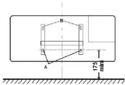
| KLE 502 KLE 1002 | ||
| A mm | 210 654 | |

Note Use appropriate fixing materials.
» Unhook the wall mounting bracket from the appliance. » Use the holes in the mounting bracket as a template for drilling the wall. » Mark out the holes for the wall mounting bracket.
Drill the holes and insert rawl plugs. » Screw the wall mounting bracket to the installation wall.
9.3 Appliance installation
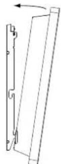
» Hook the lower slots on the back of the appliance onto the tabs of the wall mounting bracket.
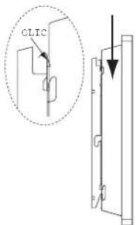
» Tilt the appliance back against the upper tabs. » Secure the appliance by pushing it towards the wall until it audibly snaps into place on the wall mounting bracket.
9.4 Removing the appliance
To release the appliance, push the metal tabs at the top of the mounting bracket towards the wall.
9.5 Power supply

WARNING Electrocution In rooms with high moisture levels, such as shower rooms and kitchens, install the connection socket at least 25 cm above the floor.

WARNING Electrocution Ensure that the power cable is not in contact with any appliance components.

Material losses Ensure the appliance can be separated from the power supply by an isolator that disconnects all poles with at least 3 mm contact separation.

Material losses Observe the type plate. The specified voltage must match the mains voltage.

Note Ensure that the cross-section of the on-site supply cable is adequate.

Note Ensure that a flush-mounted junction box for a permanent power supply is installed at a distance of at least 10 cm from the side of the appliance.

Note Carry out all electrical connection and installation work in accordance with relevant regulations.
The appliance is supplied without a plug and has a 3-core power cable.
Connect the 3-core power cable to a connection socket as illustrated:
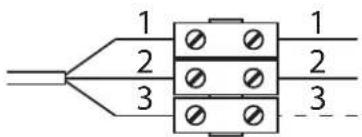
1 Neutral wire (blue) 2 Live (brown) 3 Control cable (black)
9.5.1 Control cable

Material losses If operating the appliance in programmed mode using the control cable, observe the correct polarity.

Material losses When not in use, isolate the control cable to prevent a short circuit.
There are 3 possible ways to connect the appliance:
Appliance connected without control cable
The control cable is not connected. The appliance is not controlled.
» Isolate the control cable.
Temperature setback via control cable
To reduce the temperature set at the thermostat (by 3.5°C ), the black control cable is activated via an external electronic contact (e.g. a time switch).
Control cable connected to a control unit
You can connect the appliance to any control unit that issues the following waveforms as control signals:
| Command Oscilloscope Operating | mode | Heating temper- ature | |
| No power Comfort | mode | Subject to the set- ting of the tempera- ture control knob | |
| Complete oscil- lation 230 V | Setback mode | Approx. 3.5 °C lower than the tem- perature set on the temperature control knob | |
| Semi-oscillation negative -230 V | Frost pro- tection | Frost protection temperature (ap- prox. 6 °C) | |
| Semi-oscillation positive +230 V | Appliance OFF | None | |
10. Commissioning
10.1 Initial start-up
When the appliance is first started up, it may give off a smell. Make sure that the room is adequately ventilated (with a partially open window, for example).
10.2 Appliance handover
Explain the functions of the appliance to the user. In particular, draw attention to the safety instructions. » Hand over the operating and installation instructions to the user.
11. Shutdown
Move the sliding switch to the "appliance off" position.
12. Troubleshooting

Note
The power cable may only be replaced by a qualified contractor using original spare parts supplied by us.
13. Specification
13.1 Dimensions and connections
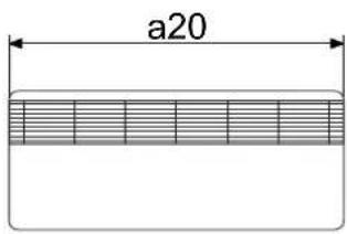
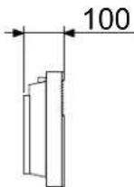
b01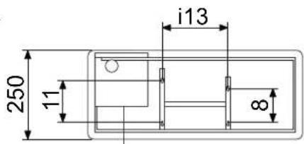
| KLE 502 KLE 1002 | ||||
| a20 | Appliance | Width | mm | 665 |
| b01 | Power connection | Entry electrical cables | ||
| i13 | Wall mounting bracket | Horizontal hole spacing | mm | 210 |
| 654 | ||||
Guarantee
The warranty conditions of our German companies do not apply to appliances acquired outside of Germany. In countries where our subsidiaries sell our products, it is increasingly the case that warranties can only be issued by those subsidiaries. Such warranties are only granted if the subsidiary has issued its own terms of warranty. No other warranty will be granted.
We shall not provide any warranty for appliances acquired in countries where we have no subsidiary to sell our products. This will not affect warranties issued by any importers.
Environment and recycling
We would ask you to help protect the environment. After use, dispose of the various materials in accordance with national regulations.
9.5 Electrical connection

WARNING burn hazard
WARNING burn hazard
WARNING burn hazard
WARNING burn hazard
1.1.2 Symbols and danger warnings
1.4 Units of measurement
Unless otherwise specified, all dimensions are given in millimeters.
2. Safety technology
2.1 Intended use
The device is intended for room heating.
The device is intended for household use. For its safe operation and maintenance, the user must follow the instructions. The device can be used not only in the household, but also, for example, in small businesses, provided the same operating conditions are observed.
Any other use not specified in this manual is considered use not in accordance with the intended purpose. Use in accordance with the intended purpose includes compliance with the requirements of this manual, as well as the manuals for the accessories used.
2.2 General safety instructions

3anpeeHOnnoB3oBaT np6op...
nHecobIOeHN MHNMaIbHbIX 6eOancbIx paCCToHn Do TAKNX PpeIMTOB, KaK, HApNmuMep, Me6eNb,3aHaBeCKN, WToPbI NTeKCTUNbHbIe N3dEINr INN npOue BocPnAmehnoiuece MaTePnaIb; B NOMeHnX, Ige n3-3a HAnuYxNIMUeCKNX Be- 1ectB, nbIIN, ra3OB INI napOB eCt bOnacHOCTb BOCIIaMemeHnI INI B3pbIBa; Heo6xoJIMO xopoOIO npOBeTpNTb NOMeHne nepeH HarpeBOM. B HeNOCpeDCTBeHHoH 6n3OCTN O TneKtpuecknx Ka6eNeI INI EMKoTeI DnTpaHCnpTIpOBKn IIN XpaHeHnroPouXn B3pbIOONaChbIX MaTePnaNoB; - pπn NOBpeJxDeHn KOHCTpyKTHBHOr ΘJeMeHTa pπbOp ra, naDeHn pπb6opa nIu HapyuWeHn erO pa60tbi; BHe NOMEeHn.

PPEyIPEKDEHNE oxor
3anpeeHNO KnaCTb Ha npn6op nnn B HenoCpeDCTBeHHo8 6n3OCTn OT Hero Tropoune, IerKOBoCpnAmehnoUncce CnTTENON3OJauuHOHbI nepeMeTbI nn60 MaTePnAnbl.

PENEYIPEXKJEHNEOxkor
He donyckaTb nonadaHnnoCTOpOHnX npedMeTOB BeHTNIAUHOHHBe OTBepCTn.3To MoKet npNBecTn K nopaxeHNO 3JIeKTPnueCKm TOKOM, Bbl3BaTb nOxapnn NOBpeDnTb np6op.

PPEyIPEKDEHNE oxor
Bo n36ekaHne noXapa He donyckaTb nepekpbltno OTBepCTn IIN BxOa N BbIXOa BO3dyxa.
Kateropnueckn 3anpeeHyo yctahabnBaT np60p Ha mKoN noBepxHOCTn, HapnpMep Ha KpoBaTN, TaK KaN npN eTOM MOrTy NepeKpbBaTbCBeHTINLAUONHHbIe OTBepCTNA.

PPEyIPPEKDEHNE oxor
Ecn np6op pa6oTaet c TaHMePOM, Bo3MoXeH HeKoHTpO npnyembl o6orpeB NOMEeHN DaKe NOcNe DOCTNKeHN HxHOI TemnepaTybl. Ecn NOMEeHne IMeET MaNEhKne pa3Mepbl, aHXoAunecBa BYTpN IIOuHE MoYr NOKHyTb erO caMOCTOrTeJIbHo, 3a Pa6oTaIOUIM np6Opom Heo6xoDm NOCTOHHbKOHTpoJb.

PPEyIpyEKDEHME TpaBMa
TETAMBBO3pacte 03net3anpeueHNOJb3OBaTbCn npu6opom,ecn OHHe HaxoJrTaNIOI NOCTOHHbIM PnCMOTPOM B3POcblx.
DeTBMBO3pacteOT3do8netpa3peuHOBKIIouaTBb BbIKIOUaTb np60p TOIbKO IOI npICMOTPOMB3PocblxnnNOCNE COOTBeCTByIOJero IHCTpyKTAka O npABINAX63ONaCHO NOB3OBAHn INOTEHNuaNBHO ONaCHOCtN B CNYae HecO6IOJeHHN 3TNX npABn. HenpeMeHHbIM YcNOBEm RAJIeTCA MOHTax np6Oba, BblONHeHHb IN BOOTBeCTBnC yKa3aHnMn HAcToJeero pyKOBODCTBa. DeTBMBO3pacteOT3do8NET3anPeueHO BKIOUaTB WTekePHyIO BUNky Bpo3eTKy IN BblONHbTpeYInpOBAHne np6Oba.
DeTAM CTapue 8 ne, a TaKKe IINuIaM c OpraHnueHHbIMN fN3UHeCKMN, CEHCOPHBIMN U yMCCTBEHNbIMN CNOOC6HOCTRMM, He IMeIOUIM ONItA N He BnAdeIOUIM INHOpMaIeN o npBope, pa3peSeHNOcNOb3OBaTB pN6Op TOnBko NOI npNCMOTPOM dpynx Nm Nn NOce COOTBeTCTByIOUero IHCTpyKTaKa O npABINax 6e3OaNACHO NpB3OBaHnN i NOTeHuaNbHO onaCHOCNTBcNyae HecO6NIODEHn 3TNx nPaBVn. He DOnyckTaB uAnOCTe DeTeC pN6OpOM. DeTNI MOrY BblONHbY hCTKY pN6OpBaN Te BVNDI TEXNHueCKORo 06cLyKINBAHn, KOtOpBle O6bHuN PpON3BOJrTCNOb3OBaTeMe, TOBko NOD pNcMOTPOM B3POCJIbIX.

The device may heat up to high temperatures and cause burns. Special caution is necessary where there are children, elderly people, or people of advanced age.

Material damage
Do not cover the device.
It is forbidden to stand on the device.
2.3 CE Mark
The CE mark certifies that the device complies with all essential requirements:
Directive on Electromagnetic Compatibility,
Directive on Low Voltage Equipment.
2.4 Technical Control Mark
This applies to cases where several devices are installed in one room.

Note
When the window is open, the air temperature regulator in the room may not operate, i.e., the device will not turn off.
During maintenance, turn off the device to avoid excessively high power consumption.
4.2.1 Night mode
In the night mode, the device automatically reduces the set comfortable room temperature by approximately 3.5°C.
The night mode should be selected before bedtime, with a minimum duration of two hours and no interruptions.
Set the slide switch to the night mode position.
To adjust the room temperature, turn the temperature setting knob counterclockwise.
4.2.2 Program modes
Using the built-in control wire, the device can be connected to an additional control unit (see chapter "Installation / Electrical connection").
Depending on the parameters set on the external control unit for the specified time of day, the device will operate in different modes (comfort, night, or frost protection).
If the slide switch is moved to the program mode position without connecting the external control unit, the device will operate in comfort mode.
4.2.3 Frost protection
In frost protection mode, the temperature regulator automatically turns on the device when the room temperature drops below 7°C.
4.3 Limiting the movement of control elements
On the rear wall of the control unit there are three pins, with which you can limit the adjustment ranges of the slide switch and fix the temperature setting knob, as well as limit its range of movement.
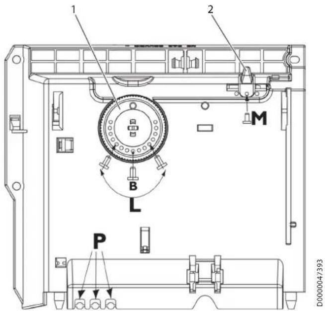
1 Temperature regulator knob 2 Slide switch for mode selection Fixing the setting knob at a position corresponding to a certain temperature Mechanical limitation of the temperature setting range to specified values and fixing the slide switch in a position corresponding to a certain mode
5. Cleaning, care and technical maintenance
The device contains no parts that require technical maintenance by the user.
Clean the device only when it is cold, using cleaning agents. Do not use abrasive or aggressive cleaning agents. Remove any dark spots on the device body with a damp cloth. Clean the upper and lower ventilation grilles of the device regularly with a vacuum cleaner.
Material damage
Do not spray cleaning agent into the air intake and exhaust openings.
6. Troubleshooting
72 Regulations, standards and provisions

Note
It is necessary to comply with all state and regional regulations and provisions.
8. Device description
8.1 Scope of delivery
The device delivery set includes:
Wall mounting bracket
8.2 Accessories
8.2.1 Additional accessories
Control device
9. Installation
9.1 Mounting the device

DANGER: Electric shock. The device must be installed so that the parts that receive water cannot come into contact with switches and regulators.

Material damage. Install the device on a vertical wall with a heat resistance of at least 85°C.

Material damage. Do not install the device directly under a wall-mounted socket.

Material damage. Observe the minimum safe distances to adjacent surfaces.
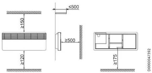
9.2 Wall mounting plate

Material damage. Observe the required distance to the floor.
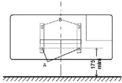
| KLE 502 | KLE 1002 | ||
| A | MM | 210 | 654 |

Instruction: Use suitable fixing material.
Remove the wall mounting plate from the device.
Use the holes in the wall mounting plate as a template for drilling holes in the wall. Mark the holes on the wall mounting plate. Drill the holes for the fixings and insert them. Attach the wall mounting plate to the wall with screws.
9.3 Mounting the device

Hang the device with the lower fixing slots in the rear wall of the device onto the wall mounting plate.
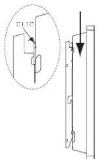
Press the device onto the upper teeth. To lock it, press the device towards the wall so that it clicks into the wall mounting plate with a characteristic sound.
9.4 Dismantling the device
To remove the device, press the metal tab in the upper part of the wall mounting plate towards the wall.
9.5 Electrical connection

WARNING: Risk of electric shock in rooms with high humidity, e.g., shower rooms. The socket for connecting the device must be located at least 25 cm above the floor.

WARNING: Risk of electric shock. Do not allow the cable to come into contact with the device components.

Material damage
The device must only be connected to the mains with all contacts separated by at least 3 mm on all poles.

Material damage
The data on the manufacturer's nameplate must be observed. The voltage must match the one indicated on the nameplate.

Note
The consumer must ensure that the cable has a sufficient cross-section.

Note
The concealed socket for permanent connection must be located at a distance of at least 10 cm from the device.

Note
Before electrical connection work, the installation must be carried out in accordance with the instructions.
The device is supplied with a three-core cable without a plug.
The three-core connecting cable should be connected to a socket, as shown in the figure:
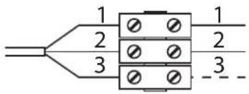
1 Neutral wire (blue) 2 Phase wire (brown) 3 Control wire (yellow)
9.5.1 Control wire

Material damage
If the device operates in a program mode using the control wire, polarity must be observed.

Material damage If the control wire is not used, it should be insulated to avoid short circuits.
There are three connection options for the device:
Connection of the device without a control wire. For control, it is not connected. The device is not connected to an external control unit.
The control wire should be insulated.
Lowering the temperature via the control wire
To change the temperature relative to the setpoint (by 3.5°C), the control wire receives a control signal from an external electronic device (e.g., a thermostat).
Connection of the control wire to an external control unit
The device can be connected to any external control unit that supplies a control signal in the following forms:
Urzhumskaya street 4,
building 2
129343 Moscow
Tel. 0495 7753889
Fax 04957753887
Switzerland
STIEBEL ELTRON AG
Industrie West
Gass 8
5242 Lupfig
Tel. 056 4640-500
Fax 0564640-501


- PLINTH CONVECTOR HEATER
- INSTALLATION
- GUARANTEE
- SPECIAL INFORMATION
- OPERATION
- GENERAL INFORMATION
- SAFETY INSTRUCTIONS
- STRUCTURE OF SAFETY INSTRUCTIONS
- SYMBOLS, TYPE OF RISK
- KEYWORDS
- OTHER SYMBOLS IN THIS DOCUMENTATION
- NOTE
- INFORMATION ON THE APPLIANCE
- UNITS OF MEASUREMENT
- SAFETY
- INTENDED USE
- GENERAL SAFETY INSTRUCTIONS
- WARNING BURNS
- WARNING INJURY
- CAUTION BURNS
- MATERIAL LOSSES
- CE DESIGNATION
- TEST SYMBOLS
- APPLIANCE DESCRIPTION
- SETTINGS
- OPERATING UNIT
- OPERATING MODES
- COMFORT MODE
- SETBACK MODE
- PROGRAMMED OPERATION
- FROST PROTECTION
- RESTRICTING THE CONTROL SWITCHES
- CLEANING, CARE AND MAINTENANCE
- TROUBLESHOOTING
- INSTRUCTIONS, STANDARDS AND REGULATIONS
- STANDARD DELIVERY
- ACCESSORIES
- FURTHER ACCESSORIES
- INSTALLATION SITE
- INSTALLING THE WALL MOUNTING BRACKET
- APPLIANCE INSTALLATION
- REMOVING THE APPLIANCE
- POWER SUPPLY
- CONTROL CABLE
- APPLIANCE CONNECTED WITHOUT CONTROL CABLE
- TEMPERATURE SETBACK VIA CONTROL CABLE
- CONTROL CABLE CONNECTED TO A CONTROL UNIT
- COMMISSIONING
- INITIAL START-UP
- APPLIANCE HANDOVER
- SHUTDOWN
- SPECIFICATION
- DIMENSIONS AND CONNECTIONS
- ENVIRONMENT AND RECYCLING
- ELECTRICAL CONNECTION
- WARNING BURN HAZARD
- SYMBOLS AND DANGER WARNINGS
- SAFETY TECHNOLOGY
- PPEYIPPEKDEHNE OXOR
- PPEYIPYEKDEHME TPABMA
- MATERIAL DAMAGE
- CE MARK
- TECHNICAL CONTROL MARK
- NIGHT MODE
- PROGRAM MODES
- LIMITING THE MOVEMENT OF CONTROL ELEMENTS
- CLEANING, CARE AND TECHNICAL MAINTENANCE
- REGULATIONS, STANDARDS AND PROVISIONS
- DEVICE DESCRIPTION
- SCOPE OF DELIVERY
- ADDITIONAL ACCESSORIES
- MOUNTING THE DEVICE
- WALL MOUNTING PLATE
- DISMANTLING THE DEVICE
- CONTROL WIRE
- SWITZERLAND
Brand : AEG
Model : KLE 1002
Category : Boiler