TS 75 EBQPlus - Saw FESTOOL - Free user manual and instructions
Find the device manual for free TS 75 EBQPlus FESTOOL in PDF.

| Brand | Festool |
| Model | TS 75 EBQPlus |
| Product type | Plunge saw |
| Weight | 6.2 kg (without mains cable) |
| Power | 1600 W |
| No-load speed | 1350 - 4400 rpm |
| Cutting depth at 0° | 0 - 75 mm |
| Cutting depth at 45° | 0 - 56 mm |
| Bevel angle | 0 - 47° |
| Blade diameter | 210 mm |
| Blade bore | 30 mm |
| Cutting width | 2.4 mm to 2.6 mm |
| Power supply | Mains, 110-230 V, 50/60 Hz |
| Main functions | Electrodynamic brake, adjustable constant speed, soft start, current limitation, thermal fuse |
| Maintenance and cleaning | Clean the ventilation slots regularly, vacuum dust, use dry compressed air for openings |
| Safety | Protective hood, blade guide, safety anti-trigger button, emergency stop |
| Spare parts and repairability | Festool after-sales service, original spare parts available at www.festool.fr/services |
| Compliance | CE, Protection class II |
| Sound pressure level | L_PA = 88 dB(A) |
| Sound power level | L_WA = 99 dB(A) |
| Vibration emission value (wood) | a_h = 3.5 m/s², K = 2 m/s² |
Frequently Asked Questions - TS 75 EBQPlus FESTOOL
User questions about TS 75 EBQPlus FESTOOL
0 question about this device. Answer the ones you know or ask your own.
Ask a new question about this device
Download the instructions for your Saw in PDF format for free! Find your manual TS 75 EBQPlus - FESTOOL and take your electronic device back in hand. On this page are published all the documents necessary for the use of your device. TS 75 EBQPlus by FESTOOL.
USER MANUAL TS 75 EBQPlus FESTOOL
en Original Instructions - Plunge-cut saw 17
natural_image
Festool cutting cutter with visible blade and blade assembly (no text or symbols on the tool itself)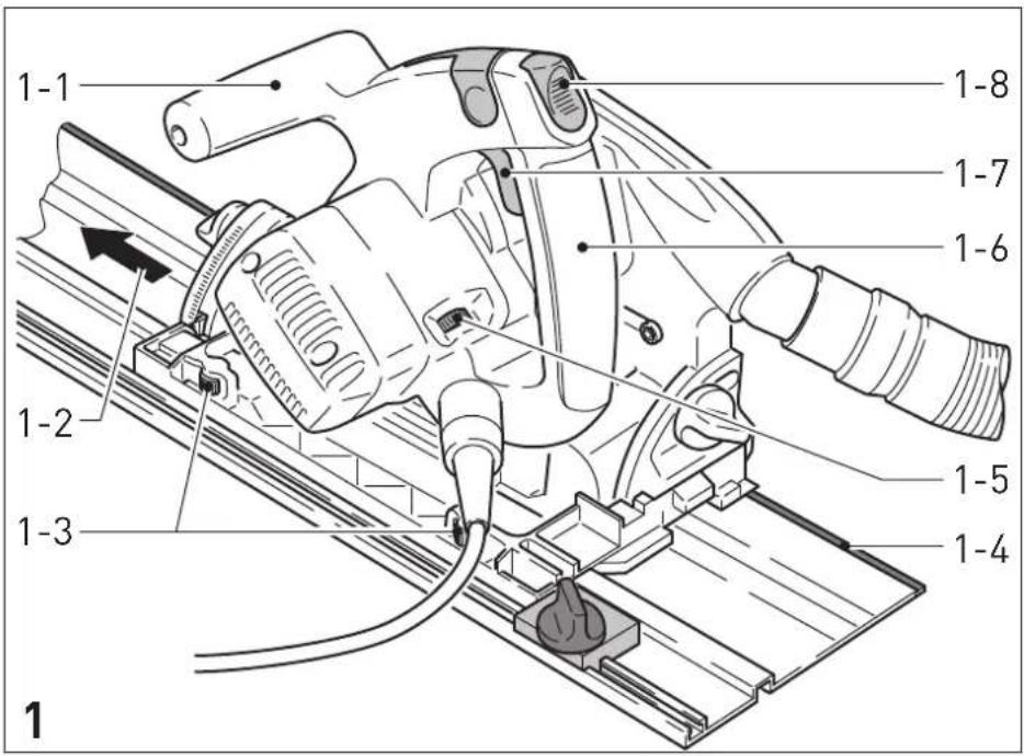
text_image
1-1 1-8 1-7 1-6 1-2 1-3 1-5 1-4 1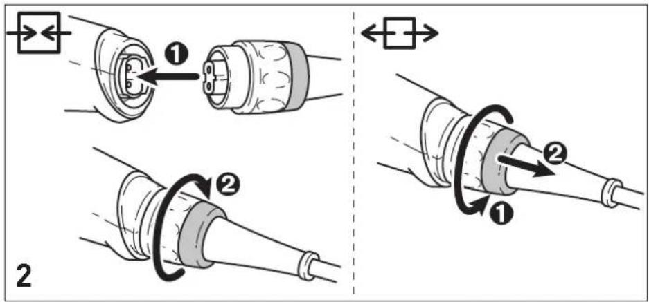
text_image
Technical diagram illustrating two-step assembly of a mechanical component with numbered parts and directional arrows indicating motion.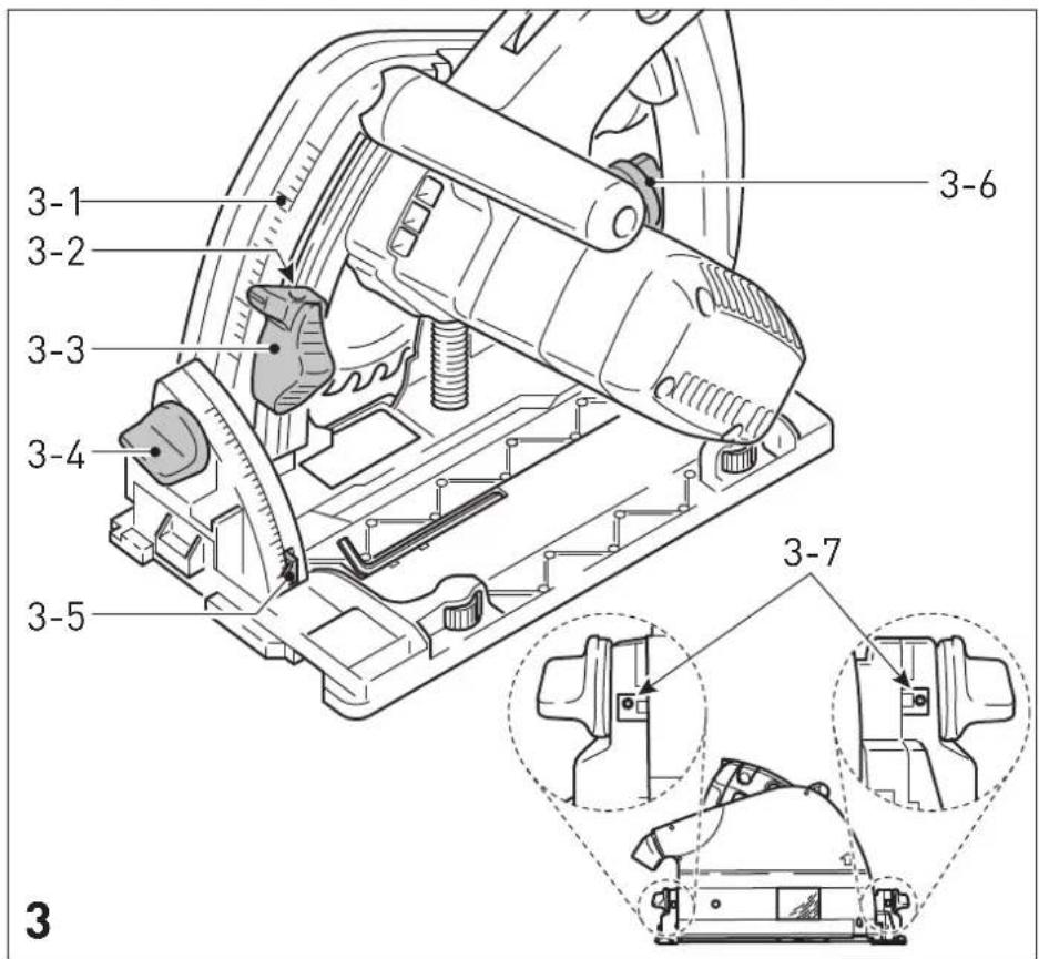
text_image
3-1 3-2 3-3 3-4 3-5 3-6 3-7 3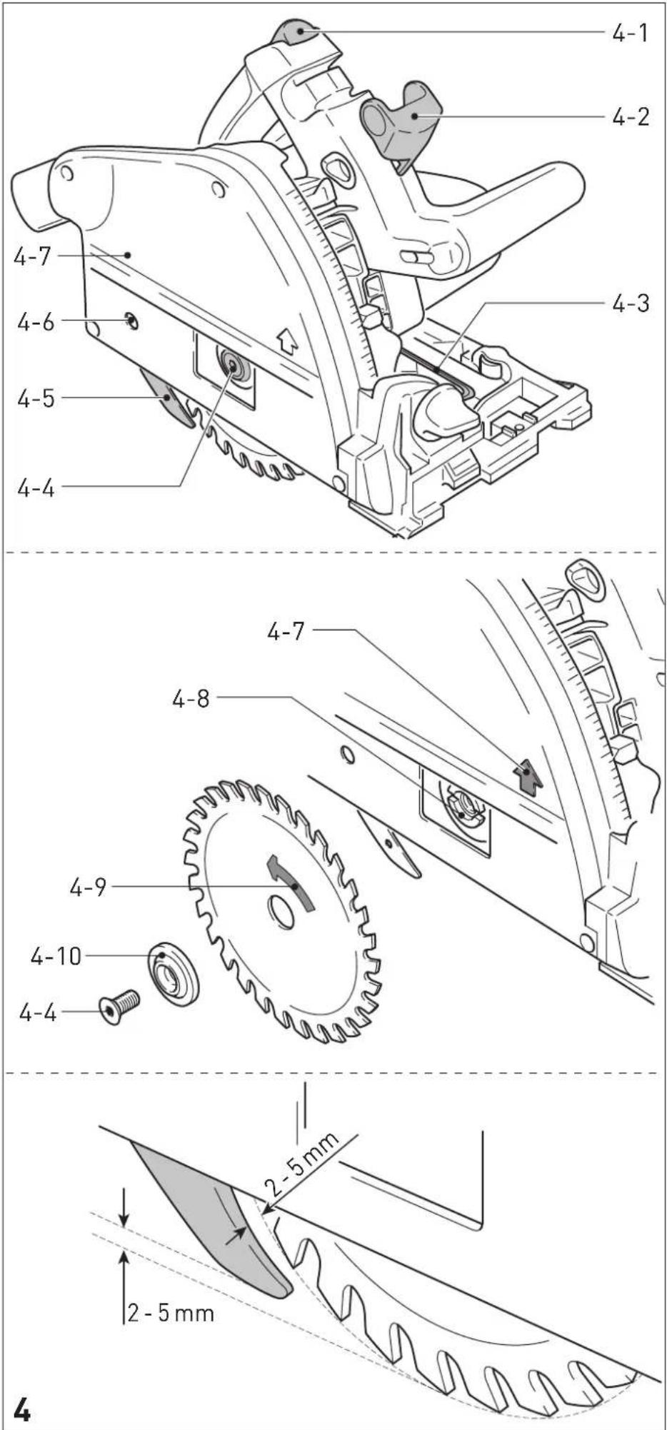
text_image
5-1 5-2 5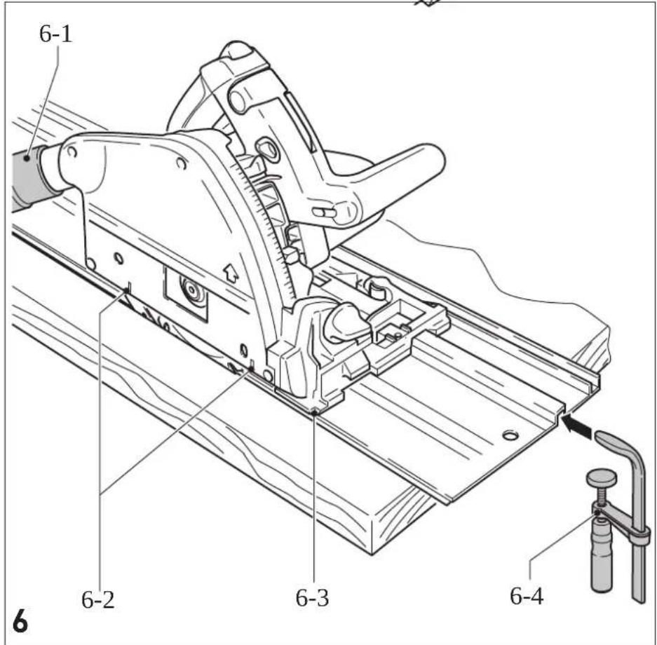
text_image
6-1 6-2 6-3 6-4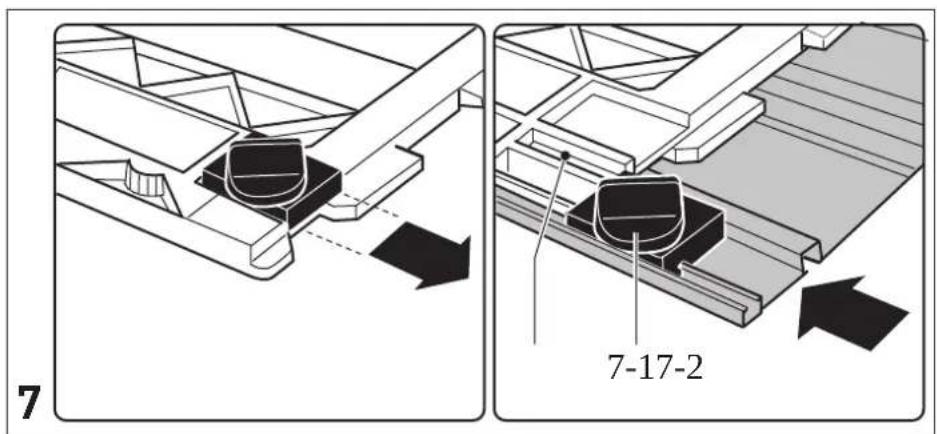
text_image
7 7-17-2Head of Product Development

text_image
i.V.R. BoxardRalf Brandt
Head of Product Conformity
Inhaltsverzeichnis
1 Symbols....17
2 Safety warnings....17
3 Intended use....20
4 Technical data.... 20
5 Operation....21
6 Settings....21
7 Working with the electric power tool.....23
8 Service and maintenance....24
9 Accessories.... 24
10 Environment....25
11 General information....25
1 Symbols

Warning of general danger

Warning of electric shock

Read the operating instructions and safety instructions.

Wear a dust mask.

Wear protective gloves when changing tools and working with raw materials.

Wear ear protection.

Wear protective goggles.

Do not dispose of it with domestic waste.

Disconnecting the mains power cable

Connecting the mains power cable

Direction of rotation of saw and the saw blade

Saw blade measurement a = diameter

Electro-dynamic run-down brake

Electronics with adjustable, constant speed and temperature monitoring

Safety class II

CE marking: Confirms the conformity of the power tool with the European Community directives.

UKCA marking: The United Kingdom Conformity Assessed symbol is a marking for products being placed on the market in the United Kingdom. It is a manufacturers indication that the product is in conformance with the relevant regulations in the UK.

Tip or advice

Handling instruction
The specified illustrations appear at the beginning of the Operating Instructions.
2 Safety warnings
2.1 General power tool safety warnings

WARNING! Read all safety warnings, instructions, illustrations and specifica-
tions provided with this power tool. Failure to follow all instructions listed below may result in electric shock, fire and/or serious injury.
Save all warnings and instructions for future reference.
The term "power tool" in the warnings refers to your mains-operated (corded) power tool or battery-operated (cordless) power tool.
2.2 Safety instructions for specific circular saws
- Only for AS/NZS: The tool shall always be supplied via residual current device with a rated residual current of 30 mA or less.
Cutting procedures

- DANGER: Keep hands away from cutting area and the blade. Keep your second hand on auxiliary handle, or motor housing. If both hands are holding the saw, they cannot be cut by the blade.
- Do not reach underneath the workpiece.
The guard cannot protect you from the blade below the workpiece.
- Adjust the cutting depth to the thickness of the workpiece. Less than a full tooth of the blade teeth should be visible below the workpiece.
- Never hold the workpiece in your hands or across your leg while cutting. Secure the workpiece to a stable platform. It is important to support the work properly to minimise body exposure, blade binding, or loss of control.
English
- Hold the power tool by the insulated handle surfaces if you intend to perform work that entails a risk of cutting into hidden power cables or the tool's own power cable. Contact with live cables transfers an electric current to metal components on the electric power tool and causes electric shocks.
- When ripping, always use a rip fence or straight edge guide. This improves the accuracy of cut and reduces the chance of blade binding.
- Always use blades with correct size and shape (diamond versus round) of arbour holes. Blades that do not match the mounting hardware of the saw will run off-centre, causing loss of control.
- Never use damaged or incorrect blade washers or bolt. The blade washers and bolt were specially designed for your saw, for optimum performance and safety of operation.
Kickback causes and related warnings
- kickback is a sudden reaction to a pinched, jammed or misaligned saw blade, causing an uncontrolled saw to lift up and out of the workpiece toward the operator;
- when the blade is pinched or jammed tightly by the kerf closing down, the blade stalls and the motor reaction drives the unit rapidly back toward the operator;
- if the blade becomes twisted or misaligned in the cut, the teeth at the back edge of the blade can dig into the top surface of the wood causing the blade to climb out of the kerf and jump back toward the operator.
Kickback is the result of saw misuse and/or incorrect operating procedures or conditions and can be avoided by taking proper precautions as given below.
- Maintain a firm grip with both hands on the saw and position your arms to resist kickback forces. Position your body to either side of the blade, but not in line with the blade. Kickback could cause the saw to jump backwards, but kickback forces can be controlled by the operator, if proper precautions are taken.
- When blade is binding, or when interrupting a cut for any reason, release the trigger and hold the saw motionless in the material until the blade comes to a complete stop. Never attempt to remove the saw from the work or pull the saw back-
ward while the blade is in motion or kick-back may occur. Investigate and take corrective actions to eliminate the cause of blade binding.
- When restarting a saw in the workpiece, centre the saw blade in the kerf so that the saw teeth are not engaged into the material. If a saw blade binds, it may walk up or kickback from the workpiece as the saw is restarted.
- Support large panels to minimise the risk of blade pinching and kickback. Large panels tend to sag under their own weight. Supports must be placed under the panel on both sides, near the line of cut and near the edge of the panel.
- Do not use dull or damaged blades. Unsharpened or improperly set blades produce narrow kerf causing excessive friction, blade binding and kickback.
- Blade depth and bevel adjusting locking levers must be tight and secure before making the cut. If blade adjustment shifts while cutting, it may cause binding and kickback.
- Use extra caution when sawing into existing walls or other blind areas. The protruding blade may cut objects that can cause kickback.
Lower guard function
- Check the lower guard for proper closing before each use. Do not operate the saw if the lower guard does not move freely and close instantly. Never clamp or tie the lower guard into the open position. If the saw is accidentally dropped, the lower guard may be bent. Raise the lower guard with the retracting handle and make sure it moves freely and does not touch the blade or any other part, in all angles and depths of cut.
- Check the operation and condition of the guard return spring. If the guard and the spring are not operating properly, they must be serviced before use. The guard may operate sluggishly due to damaged parts, gummy deposits, or a build-up of debris.
- Assure that the base plate of the saw will not shift while performing a "plunge cut". Blade shifting sideways will cause binding and likely kick back.
- Always observe that the guard is covering the blade before placing the saw down on bench or floor. An unprotected, coasting blade will cause the saw to walk backwards, cutting whatever is in its path. Be aware of the time it takes for the blade to stop after the switch is released.
Riving knife function
- Use the appropriate saw blade for the riving knife. For the riving knife to function, the body of the blade must be thinner than the riving knife and the cutting width of the blade must be wider than the thickness of the riving knife.
- Adjust the riving knife as described in this instruction manual. Incorrect spacing, positioning and alignment can make the riving knife ineffective in preventing kickback.
- For the riving knife to work, it must be engaged in the workpiece. The riving knife is ineffective in preventing kickback during short cuts.
- Do not operate the saw if the spacer wedge is bent. Even the slightest problem can cause the guard to close more slowly.
2.3 Safety instructions for the pre-assembled saw blade
Usage
- The maximum speed specified on the saw blade must not be exceeded and the speed range must be adhered to.
- The pre-installed saw blade is only designed for use in circular saws.
- Proceed with extreme care when unpacking, packing and handling the tool (e.g. installing it in the machine). There is a risk of injury from extremely sharp cutting edges!
- When handling the tool, wearing safety gloves provides a more secure hold of the tool and further reduces the risk of injury.
- Circular saw blades with cracked bodies must be replaced. Repair is not permitted.
- Circular saw blades with a combination design (soldered saw teeth) with saw tooth thickness smaller than 1 mm must no longer be used.
- Do not use tools with visible cracks or blunt or damaged cutting edges.
Installation and mounting
- Tools must be clamped in such a way that they cannot come loose during operation.
- When assembling the tools, it must be ensured that the clamping takes place on the tool hub or the clamping surface of the tool, and that the cutting edges do not come into contact with other components.
- Do not lengthen the key or tighten by hitting with a hammer.
- The clamping surfaces must be cleaned to remove contamination, grease, oil and water.
- Clamping screws must be tightened according to the manufacturer's instructions.
- Only securely installed rings, e.g. rings that have been pressed in or those that are held in position by an adhesive bond, may be used to adjust the hole diameter of circular saw blades to the spindle diameter of the machine. The use of loose rings is not permitted.
Service and maintenance
- Repairs and sanding work may only be carried out by Festool customer service workshops or experts.
- The tool design must not be changed.
- Deresinify and clean the tool regularly (cleaning agent with pH between 4.5 and 8).
- Blunt edges can be resharpened on the clamping surface to a minimum cutting edge thickness of 1 mm.
- Only transport the tool in suitable packaging - risk of injury!
2.4 Further safety instructions


Wear suitable personal protective equipment: Ear protection, protective goggles, dust mask for work that generates dust, protective gloves for working with rough materials and for changing tools.
- Harmful/toxic dust may be produced during your work (e.g. paint containing lead, certain types of wood or metals). Contact with or inhalation of this dust may pose a risk for the operating personnel or persons in the vicinity. Comply with the safety regulations that apply in your country.

- We are a P2 respiratory mask to protect your health. In enclosed spaces, ensure that there is sufficient ventilation and connect a mobile dust extractor.
English
- Check whether there are any signs of damage to the housing components, such as cracks or stress whitening. Have any damaged components repaired before using the power tool.
- Use appropriate detection devices to look for any hidden supply lines or consult your local utility company. If the insertion tool makes contact with live cables, it can result in fire and electric shock. Damage to a gas pipe can lead to an explosion. Penetration of a water pipe can result in damage to property.
2.5 Aluminium processing

When sawing aluminium, the following sures must be taken for safety reasons:
- Connect the power tool to a suitable dust extractor.
- Regularly clean dust deposits from the motor housing on the power tool.
- Use an aluminium saw blade.

Wear protective goggles.
- When sawing panels, they must be lubricated with petroleum but thin-walled profiles (up to 3 mm) can be sawed without lubrication.
2.6 Emission levels
The levels determined in accordance with EN 62841 are typically:
Sound pressure level L _PA = 88 dB(A)
Sound power level L _WA = 99 dB(A)
Uncertainty K = 3 dB

CAUTION
Noise generated when working Risk of damage to hearing
▶ Use ear protection.
Vibration emission level a_h (vector sum for three directions) and uncertainty K measured in accordance with EN 62841:
| Sawing wood | a_h 3,5 m/s ^2 |
| K = 2 m/s ^2 | |
| Sawing metal | a_h 3,5 m/s ^2 |
| K = 2 m/s ^2 |
The specified emission levels (vibration, noise)
- are used to compare machines.
- They are also used for making preliminary estimates regarding vibration and noise load during operation.
- They represent the primary applications of the power tool.

CAUTION
The emission values may deviate from the specified values. This is dependent on how the tool is used and the type of workpiece being machined.
▶ The actual load during the entire operating cycle must be evaluated.
▶ Depending on the actual load, suitable protective measures must be defined in order to protect the operator.
3 Intended use
Circular saws are designed for sawing wood, materials similar to wood, gypsum and cement-bonded fibre materials and plastics. When fitted with the special saw blades for aluminium that are offered by Festool, these machines can also be used for sawing aluminium.
Materials containing asbestos must NOT be processed.
Do not use cutting or abrasive wheels.
This power tool may only be used by experts or instructed persons.

The user is liable for improper or non-in-tended use.
3.1 Saw blades
Only use saw blades with the following dimensions:
– Saw blades according to EN 847-1
- Saw blade diameter 210 mm
- Cutting width 2.4 mm to 2.6 mm
- Locating bore 30 mm
- Standard blade thickness Max. 1.8 mm
- Suitable for speeds of up to 5000 rpm
Festool saw blades comply with EN 847-1.
Only saw materials for which the saw blade in question has been designed.
4 Technical data
Circular saw TS 75 EBQ, TS 75 EQ
Performance 1600 W
(110 V version: 13 A)
no-load speed
1350-4400 rpm
Circular saw TS 75 EBQ, TS 75 EQ
Inclination 0–47°
Cutting depth at 0° 0–75 mm
Cutting depth at 45^ 0–56 mm
Saw blade measurement 210 x 2.4 x 30 mm
Weight (without power cable) 6.2 kg
5 Operation

WARNING
Unauthorised voltage or frequency. Risk of accidents
- The mains voltage and the frequency of the power source must correspond to the specifications on the name plate.
▶ In North America, only Festool machines with the voltage specifications 120 V/60 Hz may be used.

CAUTION
Heating of the Plug it connection if bayonet fitting is not completely locked Risk of burns
▶ Before switching on the power tool, make sure that the bayonet fitting at the mains cable is closed fully and locked.

Always switch off the machine before connecting and disconnecting the mains
power cable.
Connecting and disconnecting the mains power cable - see Fig. [2].

Slide the safety lock [1-8] upwards and press the on/off switch [1-7] (press =
ON / release = OFF).
Pressing the safety lock unlocks the plunging mechanism. The saw unit can then be moved downwards. This causes the saw blade to emerge from the protective cover.

When the machine is lifted, the saw unit springs back into its initial position.
6 Settings

WARNING
Risk of injury, electric shock
▶ Always disconnect the mains plug from the socket before performing any work on the machine.
6.1 Electronics
The machine (TS 75 EBQ, TS 75 EQ) comes with full-wave electronics with the following properties:
Smooth start-up
The electronically controlled smooth start-up function ensures that the power tool starts up smoothly.
Constant speed
The motor speed is electronically kept constant. This ensures a uniform cutting speed even when under load.
Speed control
You can continuously adjust the speed within the speed range using the adjusting wheel [1-5] (see "Technical data"). This enables you to optimise the cutting speed to suit each surface.
Speed range per material
| Solid wood (hard, soft) 6 | |
| Chipboard and hardboard 3-6 | |
| Laminated wood, blockboard, veneered and laminated panels | 6 |
| Laminate, mineral materials 4-6 | |
| Plaster- and cement-bonded chipboard and fibreboard | 1-3 |
| Aluminium panels and profiles up to 15 mm | 4-6 |
| Plastics, fibre-reinforced plastics, paper and fabric | 3-5 |
| Acrylic glass 4-5 | |
Temperature cut-out
The power supply is restricted and the speed reduced if the motor exceeds a certain temperature. The power tool continues operating at reduced power to allow the ventilator to cool the motor quickly. The power tool starts up again automatically once the motor has cooled sufficiently.
English
Current limiting
Current limiting prevents excessive current consumption under extreme overload, which can lead to a decrease in the motor speed. The motor immediately restarts after the load is removed.
Brake
The TS 75 EBQ comes with an electronic brake. The saw blade is stopped electronically within approximately two seconds of switching off the machine.
6.2 Adjusting the cutting depth
The cutting depth can be set at 0–75 mm at the cutting depth stop.
▶ Push down on the cutting depth stop [3-3] and move it to the required cutting depth (the values specified on the scale [3-1] apply to 0° cuts without a guide rail),
▶ Release the cutting depth stop (the cutting depth stop clicks into pace at 1 mm increments).
The saw unit can now be pushed downwards as far as the cutting depth that is set.
A threaded pin (M4x8 up to M4x12) can be screwed into the hole [3-2] in the cutting depth stop. By turning the threaded pin, the cutting depth can be adjusted even more precisely (+/- 0.1 mm).
6.3 Adjusting the cutting angle
The saw unit can be swivelled between 0^ and 47^ :
▶ Open the rotary knobs [3-4, 3-6].
▶ Swivel the saw unit to the desired cutting angle [3-5].
▶ Retighten the rotary knobs.
The two end positions are set at the plant to 0^ and 45^ . By turning the two threaded pins [3-7] in an anti-clockwise direction, the end position can be increased from 45^ to a maximum of 47^ .
6.4 Selecting the saw blade
Festool saw blades are identified by a coloured ring. The colour of the ring represents the material for which the saw blade is suited.
Refer to the necessary saw blade data (see section 3.1).
Colour Material Symbol
Yellow Wood


Red Laminate, mineral material


Green Plaster- and cement-bonded chipboard and fibreboard


Blue Aluminium, plastic


6.5 Changing the saw blade

WARNING
Risk of injury, electric shock
▶ Always disconnect the mains plug from the socket before performing any work on the machine.

CAUTION
Risk of injury from hot and sharp insertion tool
- Do not use any blunt or faulty insertion tools.
- Wear protective gloves when handling an insertion tool.
Remove the saw blade
▶ Swivel the machine to 0^ before replacing the saw blade and adjust the maximum cutting depth.
▶ Turn the lever [4-2] as far as it will go.
▶ Slide the safety lock [4-1] upwards and push the saw unit downwards until it clicks into place.
▶ Loosen the screw [4-4] using the Allen key [4-3].
▶ Remove the saw blade.
Inserting the saw blade
WARNING! Check the screws and flange for contamination and only use clean and undamaged parts.
▶ Insert the new saw blade.
WARNING! The direction of rotation of the saw blade [4-9] and saw [4-7] must match. Serious injuries may occur in the event of non-compliance.
▶ Insert the outer flange [4-10] so that the pin engages in the recess on the inner flange.
▶ Tighten the screw [4-4].
▶ Reposition the lever [4-2].
6.6 Adjusting the riving knife
▶ Turn the lever [4-2] as far as the stop,
▶ Slide the safety lock [4-1] up and push the saw unit down until it locks into place,
▶ Loosen the screw [4-6] using the hex key [4-3],
▶ Adjust the riving knife according to the diagram [4]
▶ Tighten the screw [4-6],
▶ Reposition the lever [4-2].
6.7 Dust extraction

WARNING
Heath hazard posed by dust
▶ Always work with an extractor.
▶ Comply with national regulations.
Festool mobile dust extractor
A Festool mobile dust extractor with a suction hose diameter of 27/32 mm or 36 mm (36 mm recommended due to the reduced risk of clogging) can be connected to the extractor connector [6-1].
The adapter on a 27 diameter suction hose is inserted into the angle adapter. The adapter on a 36 diameter suction hose is inserted over the angle adapter.
CAUTION! A static charge may build up if no antistatic suction hose is used. The user may receive an electric shock and the power tool's electronics may be damaged.
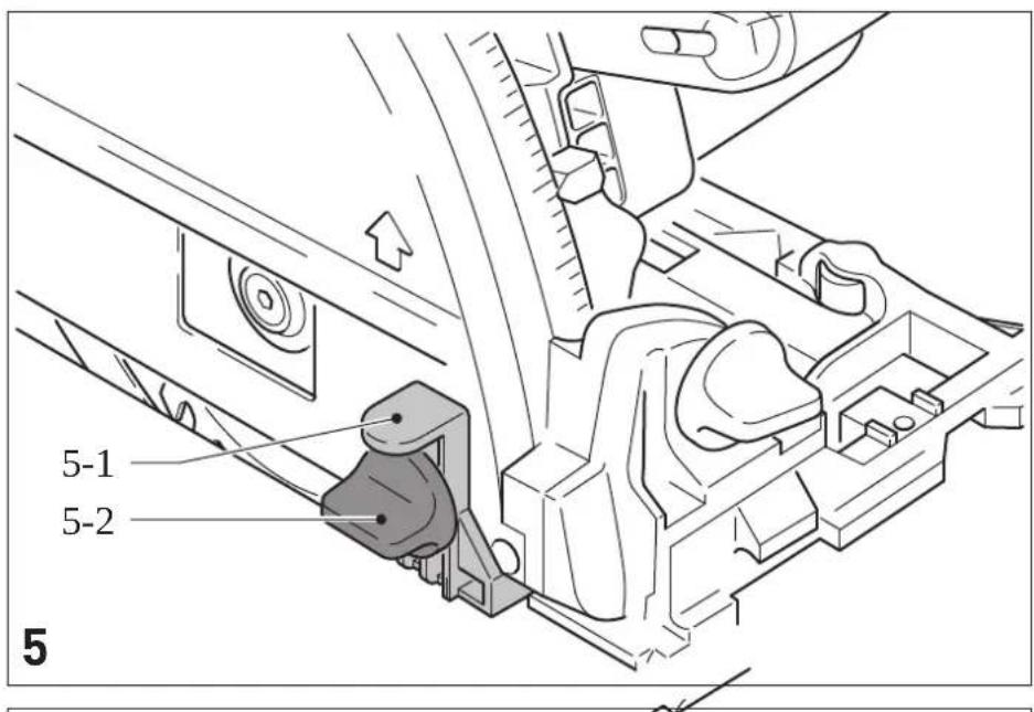
6.8 Installing the splinter guard
With 0^ cuts, the splinter guard (accessory) significantly improves the quality of the cutting edge of the sawn-off workpiece on the upper side.
▶ Place the splinter guard [5-1] onto the protective cover,
- Position the machine on the workpiece/guide rail,
▶ Push down on the splinter guard until it makes contact with the workpiece and tighten it using the rotary knob [5-2],
▶ Saw in the splinter guard (machine at maximum cutting depth and speed level 6).
7 Working with the electric power tool

When working on the machine, observe all of the safety warnings that are listed at the start as well as the following rules:
Before starting
- Before each use, check whether the drive unit with the saw blade correctly and fully swivels back up into its initial position in the protective housing. Do not use the saw if the upper end position is not secured. Never clamp or secure the swivelling drive unit at a specific cutting depth. This would mean that the saw blade is not protected.
- Check the plunging mechanism prior to use and do not use the machine if it does not work correctly.
- Check that the saw blade is securely in place.
- Make sure that the rotary knob [3-4, 3-6] is tightened before starting work.
- Make sure that extractor hose and mains power cable do not snag the entire saw cut, either on the workpiece, the workpiece support or hazards on the ground.
- Always secure the workpiece in such a way that it cannot move during machining.
- Position the workpiece so that it is stress-free and level.
During work
- When working, always hold the power tool with both hands on the handles [1-1, 1-6]. This is a prerequisite for precise work and is essential for plunge-cutting. Plunge into the workpiece slowly and evenly.
- Only guide the power tool towards the workpiece when it is switched on.
- Always push the saw forwards [1-2], and never towards yourself.
- Adapt the infeed speed to prevent the cutters on the saw blade from overheating and prevent plastic materials from melting during cutting. The harder the material to be sawn, the lower the feed speed needs to be.
- Do not work with the machine if the electronics are defective, because this may lead to excessive speeds. You can tell if the electronics are defective if there is no smooth start-up or if it is not possible to regulate the speed or where smoke is present or if there is a smell of burning coming from the machine.
7.1 Sawing along the scribe mark
The gauge marker [6-3] displays the cutting line for 0° and 45° cuts (without a guide rail).
7.2 Cutting sections
Position the machine with the front part of the saw table on the workpiece, switch on the machine, push it down to the set cutting depth and push it forward in the cutting direction.
7.3 Sawing cut-outs (plunge cuts)

In order to avoid kickbacks, the following instructions must always be followed when plunge cutting:
- Always position the machine with the rear edge of the saw table against a fixed stop. When working with the guide rail, position the machine at the kickback stop [7-1], which is clamped to the guide rail (see Fig. [7]; when not in use, the kickback stop can be stored by the guide plate [7-2] of the machine).
- Always hold the machine securely using both hands and plunge slowly.
Procedure
Position the machine on the workpiece and place it against a stop (kickback stop), switch on the machine, slowly push it down to the set cutting depth and push it in the cutting direction. The marks [6-2] indicate the absolute front and rear cutting points of the saw blade (210 mm diameter) when using the saw at maximum cutting depth with the guide rail.
8 Service and maintenance
WARNING
Risk of injury, electric shock
▶ Always pull the mains plug from the socket before performing any servicing and maintenance work.
▶ All maintenance and repair work which requires the housing to be opened should always be carried out by an authorised service workshop.

Customer service and repairs must only be carried out by the manufacturer or service workshops. Find the nearest address at:
www.festool.co.uk/service

Always use original Festool spare parts. Order no. at:
www.festool.co.uk/service
Observe the following instructions:
▶ Damaged safety devices and parts, such as a faulty lever for changing tools [1-8] , must be properly repaired or replaced in a recognised specialist workshop, unless otherwise indicated in the operating manual.
▶ Check the condition and fault-free functioning of the recuperating springs, which push the entire drive mechanism bearing into the upper protected end positions.
▶ To ensure constant air circulation, always keep the cooling air openings in the housing clean and free of blockages.
▶ Use an extractor on all openings in order to remove wood chips and splinters from the power tool. Never open the protective lid [4-7].
- When working with plaster- and cement-bonded fibreboards, clean the tool particularly thoroughly. Clean the vents of the power tool and on/off switch using dry, oil-free compressed air. Otherwise, gypsum dust deposits may build up inside the power tool's housing and on the on/off switch and harden when exposed to humidity. This may impair the switching mechanism
9 Accessories
The order numbers of the accessories and tools can be found in the Festool catalogue or on the Internet at "www.festool.com".
9.1 Parallel stop, extension table
A parallel stop can be used for sections up to 180 mm wide. The parallel stop can also be used as an extension table.
9.2 Guide system
The guide rail enables you to make clean, accurate cuts while simultaneously protecting the surface of the workpiece from damage.
In conjunction with the extensive range of accessories, exact angled cuts, mitre cuts and fitting work can be completed with the guide system. The option of attaching the guide rail securely using clamps [6-4] ensures safer working conditions.
▶ Adjust the guide play between the saw table and the guide rail using the two adjustable jaws [1-3].
Bed in the splinter guard [1-4] before using the guide rail for the first time:
▶ Set the machine speed to 6.
▶ Place the machine at the rear end of the guide rail together with the complete guide plate.
▶ Switch on the machine.
- Push down the machine slowly to the max. preset cutting depth and cut along the full length of the splinter guard without stopping.
The edge of the splinter guard now corresponds exactly to the cutting edge.
(i) Position the guide rail for sawing the splinter guard on a test piece of wood.
9.3 Multifunction table
The MFT/3 multifunction table enables workpieces to be clamped easily and small and large workpieces to be machined safely and precisely in conjunction with the guide system. Its versatile application options allow you to work efficiently and ergonomically.
9.4 Saw blades, other accessories
In order to saw different materials quickly and cleanly, Festool offers saw blades for all applications and these are specially designed for your Festool saw.
10 Environment

Do not dispose of the device in the household waste! Recycle devices, accessories and packaging. Observe applicable national regulations.
EU only: In accordance with the European Directive on waste electrical and electronic equipment and implementation in national law, used power tools must be collected separately and handed in for environmentally friendly recycling.
Information on REACH: www.festool.com/reach
11 General information
Imported into the UK by
Festool UK Ltd
1 Anglo Saxon Way
Bury St Edmunds
IP30 9XH
Great Britain
Sommaire
natural_image
Four black circular icons representing head, face, helmet, and gloves (no text or symbols)2.5 Aluminiumbearbetning
natural_image
Four black circular icons representing safety and recognition symbols: helmet, glasses, headphones, and hand (no text or labels)natural_image
Four black circular icons representing different workplace safety symbols: helmet, glasses, head, and hand (no text or labels)-
Declaration of Conformity
We as the manufacturer Festool GmbH, Wertstraße 20, 73240 Wendlingen, Germany declare under our sole responsibility that the product(s):
Designation:
Designation of Type(s):
Serial number(s) 1):
Plunge-cut saw
TS 75 EQ, TS 75 EBQ
204839, 204838
fulfills all the relevant provisions of the following UK Regulations:
S.I. 2008/1597
S.I. 2016/1091
S.I. 2012/3032
Supply of Machinery (Safety) Regulations 2008
Electromagnetic Compatibility Regulations 2016
Restriction of the Use of Certain Hazardous Substances in Electrical and Electronic Equipment Regulations 2012
and are manufactured in accordance with the following designated standards:
• BS EN 62841-1: 2015
• BS EN 62841-2-5: 2014
• BS EN 55014-1:2017
• BS EN 55014-2:2015
• BS EN IEC 61000-3-2:2019
• BS EN 61000-3-3:2013
• BS EN IEC 63000:2018
1) in the specified serial number range (S-Nr.) from 400000000 - 499999999

Place and date of declaration: Wendlingen, 15.04.2021
Signed on behalf of and in name of Festool GmbH

text_image
ppa. rssAMarkus Stark
Head of Productdevelopment
i.v.Q. Boxard
Ralf Brandt
Head of Productconformity