
SSMUW - Projector Accessory Chief - Free user manual and instructions
Find the device manual for free SSMUW Chief in PDF.

| Product Type | Universal interface mounting brackets for projector |
| Brand | Chief |
| Model | SSMUW |
| Compatibility | Projectors with standard mounting holes; compatible with UL-listed RSA/RSM mounts |
| Maximum load capacity | 11.34 kg (25 lb) |
| Material | Steel |
| Color | Black |
| Main plate dimensions (approx.) | 20 x 15 cm (estimated) |
| Net weight (approx.) | 0.5 kg (estimated) |
| Kit contents | Main plate, 2 feet, screw adapters, height adjustment nuts, Phillips screws (various sizes), M4 flat washers, 1/4-20" Allen nuts, optional security screws |
| Mounting | On the projector (via mounting holes) and on the RSA/RSM mount |
| Height adjustment | Yes, via adjustment nuts |
| Security | Optional security screws and cable ties |
| Intended use | Indoor only |
| Warranty | Limited manufacturer warranty (check with Chief) |
| Care and cleaning | Clean with a soft, dry cloth; do not use abrasive products |
| Certifications | Compatible with UL-listed RSA/RSM mount |
| Tools required for installation | Allen key, screwdriver |
Frequently Asked Questions - SSMUW Chief
User questions about SSMUW Chief
0 question about this device. Answer the ones you know or ask your own.
Ask a new question about this device
Download the instructions for your Projector Accessory in PDF format for free! Find your manual SSMUW - Chief and take your electronic device back in hand. On this page are published all the documents necessary for the use of your device. SSMUW by Chief.
USER MANUAL SSMUW Chief
Milestone AV Technologies, and its affiliated corporations and subsidiaries (collectively, "Milestone"), intend to make this manual accurate and complete. However, Milestone makes no claim that the information contained herein covers all details, conditions or variations, nor does it provide for every possible contingency in connection with the installation or use of this product. The information contained in this document is subject to change without notice or obligation of any kind. Milestone makes no representation of warranty, expressed or implied, regarding the information contained herein. Milestone assumes no responsibility for accuracy, completeness or sufficiency of the information contained in this document.
Chief® is a registered trademark of Milestone AV Technologies. All rights reserved.

IMPORTANT SAFETY INSTRUCTIONS

WARNING: A WARNING alerts you to the possibility of serious injury or death if you do not follow the instructions.

CAUTION: A CAUTION alerts you to the possibility of damage or destruction of equipment if you do not follow the corresponding instructions.

WARNING: Failure to read, thoroughly understand, and follow all instructions can result in serious personal injury, damage to equipment, or voiding of factory warranty! It is the installer's responsibility to make sure all components are properly assembled and installed using the instructions provided.

WARNING: Failure to provide adequate structural strength for this component can result in serious personal injury or damage to equipment! It is the installer's responsibility to make sure the structure to which this component is attached can support five times the combined weight of all equipment. Reinforce the structure as required before installing the component.

WARNING: Exceeding the weight capacity can result in serious personal injury or damage to equipment! It is the installer's responsibility to make sure the combined weight of all components attached to the SSBU/SSMU does not exceed 25 lbs (11.34 kg).

WARNING: Use this mounting system only for its intended use as described in these instructions. Do not use attachments not recommended by the manufacturer.

WARNING: Never operate this mounting system if it is damaged. Return the mounting system to a service center for examination and repair.

WARNING: Do not use this product outdoors.
--SAVE THESE INSTRUCTIONS--
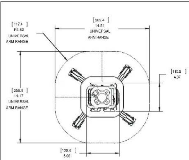
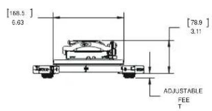
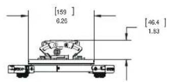
DIMENSIONS
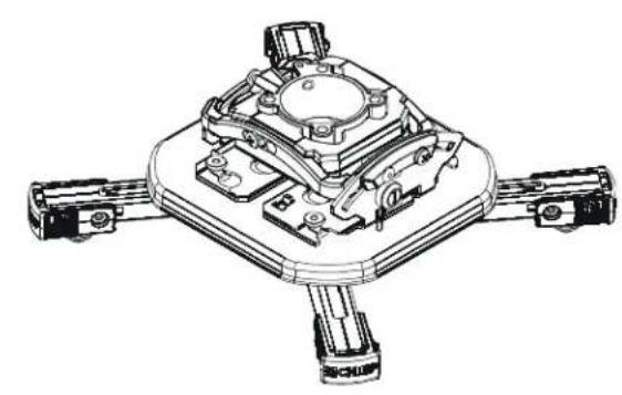
SSMU with RSM shown)
LEGEND
| Tighten Fastener | Pencil Mark | ||
| Apretar elemento de fijación | Marcar con lápiz | ||
| Befestigungsteil festziehen | Stiftmarkierung | ||
| Apertar fixador | Marcar com lápis | ||
| Serrare il fissaggio | Segno a matita | ||
| Bevestiging vastdraaien | Potloodmerkteken | ||
| Serrez les fixations | Marquage au crayon | ||
| Loosen Fastener | Drill Hole | ||
| Aflojar elemento de fijación | Perforar | ||
| Befestigungsteil lõsen | Bohrloch | ||
| Desapertar fixador | Fazer furo | ||
| Allentare il fissaggio | Praticare un foro | ||
| Bevestiging losdraaien | Gat boren | ||
| Desserrez les fixations | Percez un trou | ||
| Phillips Screwdriver | Socket Wrench | ||
| Destornillador Phillips | Llave de cubo | ||
| Kreuzschlitzschraubendreher | Llave de cubo | ||
| Chave de fendas Phillips | Chave de caixa | ||
| Cacciavite a stella | Chiave a brugola | ||
| Kruiskopschroevendraier | Dopsleutel | ||
| Tournevis à pointe cruciforme | Clé à douilles | ||
| Open-Ended Wrench | Remove | ||
| Llave de boca | Quitar | ||
| Gabelschlüssel | Entfernen | ||
| Chave de bocas | Remover | ||
| Chiave a punte aperte | Rimuovere | ||
| Steeksleutel | Verwijderen | ||
| Clé à fourche | Retirez | ||
| By Hand | Optional | ||
| A mano | Optional | ||
| Von Hand | Optional | ||
| Com a maior | Optional | ||
| A mano | Opzionale | ||
| Met de hand | Optie | ||
| À la main | En option | ||
| Hex-Head Wrench | Security Wrench | ||
| Llave de cabeza hexagonal | Llave de seguidad | ||
| Sechskantschlüssel | Sicherheitsschlüssel | ||
| Chave de:bacea sextavada | Chave de segurança | ||
| Chiave esagonale | Chiave di sicurezza | ||
| Zeskantsleutel | Veiligheidssleutel | ||
| Clé à tête hexagonale | Clé de sécurité |
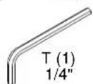
TOOLS REQUIRED FOR INSTALLATION

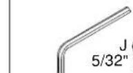
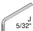
1/4" (included) 5/32" (security) (included)
2
PARTS

A (1) [SSBU interface plate]
(OR)
A (1) [SSMU interface plate]
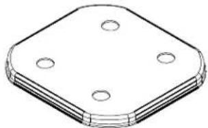
B (1) [Base plate bracket]
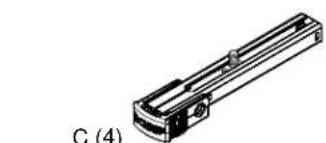
[SSBU/SSMU leg]

D (4)
umb nut!
BU only)
[All Points Security Kit]

10-24 x 1/4" [SSBU Only]

8-32 x 3/8" [SSBU Only]

G (4) H (1) 10-24 x 3/8" 5/16-18 x 1/2" [SSBU Only] [SSBU Only]

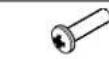
[Universal Projector Interface Hardware Kit]
K (4) 8-32 x 1/4"
L (4) M2.5 x 10mm

M (4) M3 x 10mm

N (4)
M4×10mm

M5 x 14mm

Q(4) M6 x 14mm

R (4) M4

S (4) 1/4-20
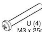
[Universal Hardware Kit - Long Screws]
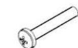
V (4) M4 x 25mm
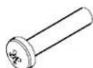
W (4) M5 x 25mm
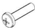
X (4) x 25mm

Y(4) .500x.257x.625
ASSEMBLY AND INSTALLATION
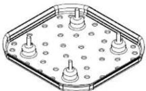
Remove Screw Adapters from SSBU/SSMU Legs
- Press locking buttons on SSBU/SSMU leg (C) firmly and simultaneously push clip cover toward enclosed sliding stud mount bracket and screw. (See Figure 1)
- Screw adapter and attached height-adjustment nut will be released. Set aside for later use. (See Figure 1)
- Repeat Steps 1-2 for each leg to be used in installation.
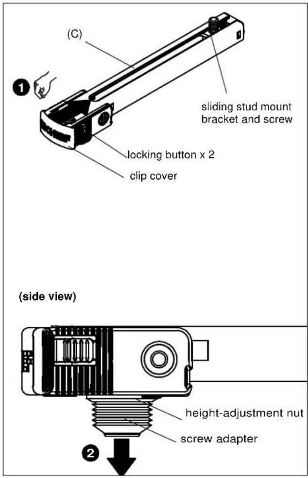
Figure 1
Attach Projector to SSBU/SSMU

WARNING: Exceeding the weight capacity can result in serious personal injury or damage to equipment! It is the installer's responsibility to make sure the combined weight of all components attached to the SSBU/SSMU interface brackets does not exceed 25 lbs (11.34 kg).
-
Determine proper size screw to insert into projector. Test Phillips screws (L, M, N, P, or Q) provided until one fits the projector holes.
-
Insert screws through M4 flat washers (R), screw adapters with height-adjustable nuts and into projector holes. (See Figure 2)
NOTE: Only use washers (R) if using L or M screws to attach screw adapters to projector.
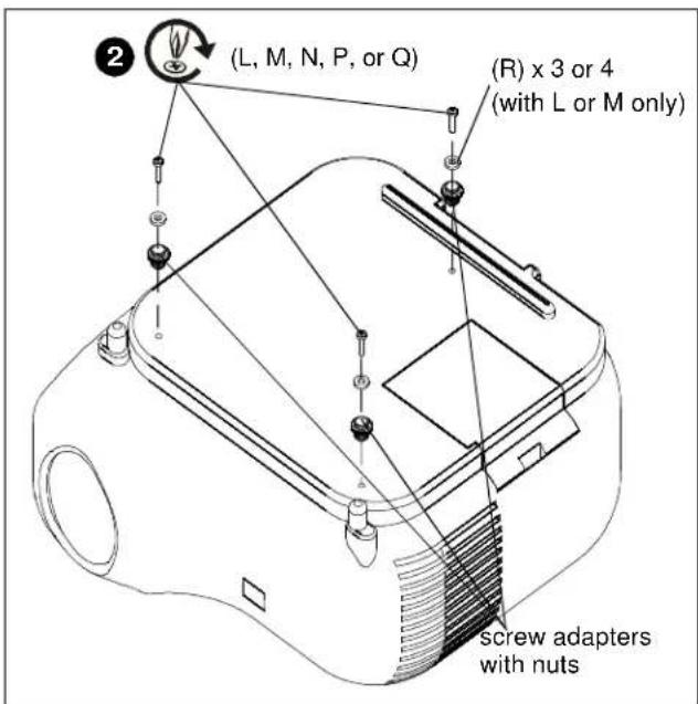
Figure 2
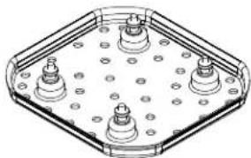
- Adjust height-adjustment nuts to desired level. (See Figure 3)
NOTE: Height-adjustment nuts should be adjusted as low as possible while ensuring that the legs will always clear any elevated surfaces on the projector. All nuts must be adjusted to the same level to ensure an even mount.
IMPORTANT ! : The optional Universal Hardware Kit - Long Screws (see Parts drawing) may be used if there is interference with any part of the projector, and more height is required to clear elevated surfaces of the projector.
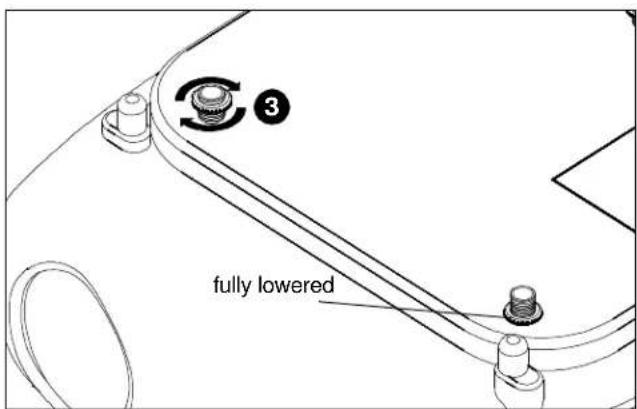
Figure 3
- Place SSBU/SSMU legs (C) over screw adapters and height-adjustment nuts. (See Figure 4)
NOTE: Make sure arm latch clips are in the unlocked position.
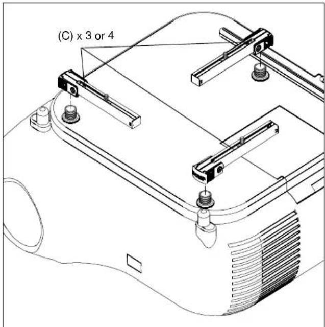
Figure 4
- Press locking buttons on SSBU/SSMU leg (C) firmly and simultaneously push clip cover away from enclosed sliding stud mount bracket until clip cover is in the locked position. (See Figure 5)
- Repeat Step 5 for remaining legs.

WARNING: Make sure legs have securely locked onto height-adjustable nuts with the latch clips. If the legs are not properly locked onto the adapters, the projector could fall from the SSBU/SSMU mount causing SERIOUS INJURY or DEATH!

Figure 5
- Maneuver legs so that sliding stud mount brackets and screws are towards the middle of the projector. (See Figure 6) and (See Figure 7)
- Position sliding stud mount brackets and screws so that SSBU or SSMU main plate (A) can be evenly mounted to legs. (See Figure 6) and (See Figure 7)
- Secure SSBU/SSMU main plate to SSBU/SSMU legs by installing 1/4-20" Allen nuts (S) to screws on SSBU/SSMU legs. (See Figure 6) and (See Figure 7)
NOTE: The following examples are two of many possible scenarios based on typical examples of mounting hole patterns. Specific connection points will vary based on the hole pattern. Multiple scenarios may be used for each specific hole pattern as long as the weight of the projector is centered and balanced after mounting.
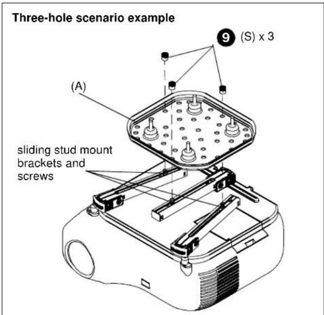
Figure 6
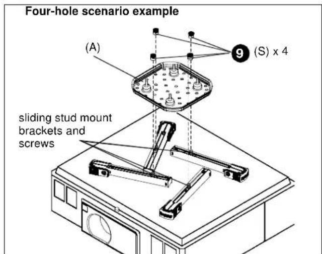
Figure 7
Attach SSBU/SSMU to UL Listed RSA or RSM
- On SSBU, partially install four thumb nuts (D) to SSBU main plate screws. (See Figure 8)
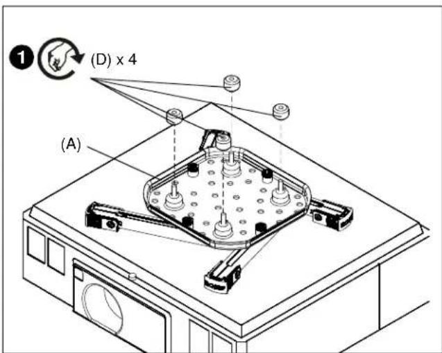
Figure 8
- Place SSBU/SSMU base plate (B) over SSBU/SSMU interface plate (A). (See Figure 9)
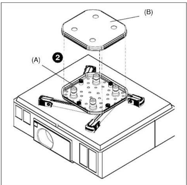
Figure 9
- Attach SSBU/SSMU to RSA/RSM. Refer to RSA/RSM installation manual for details.
Security Screw Installation (Optional)
- Install #8-32 x 3/8" button head security screws (F) into security holes on SSBU/SSMU legs. (See Figure 10)
NOTE: Up to two security screws can be installed on each leg. It is recommended that screws be installed in holes that are difficult to access to achieve maximum security.
NOTE: Cable ties (not included) may be used instead of the security screws. Thread cable tie through both holes on leg and secure cable tie.
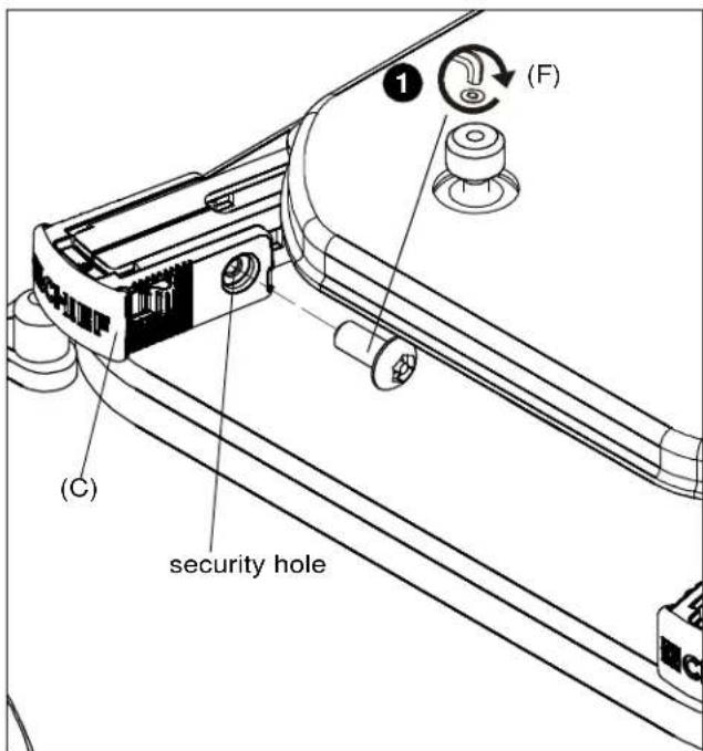
Figure 10
CLAUSES DE NON-RESPONSABILITÉ
10-24 x 1/4" [nur SSBU]

8-32 x 3/8" [nur SSBU]

G (4) 10-24 x 3/8" [nur SSBU]

H (1) 5/16-18 x 1/2" [nur SSBU]
5/32" (Sicherheit)