IQ400 - Counter CANNONDALE - Free user manual and instructions
Find the device manual for free IQ400 CANNONDALE in PDF.
User questions about IQ400 CANNONDALE
0 question about this device. Answer the ones you know or ask your own.
Ask a new question about this device
Download the instructions for your Counter in PDF format for free! Find your manual IQ400 - CANNONDALE and take your electronic device back in hand. On this page are published all the documents necessary for the use of your device. IQ400 by CANNONDALE.
USER MANUAL IQ400 CANNONDALE
THANK YOU FOR PURCHASING A CANNONDALE
Congratulations on your purchase of a Cannondale IQ Series computer.
Proper setup and operation will greatly enhance this product's usefulness and your enjoyment.
Please follow all Warnings and read all sections of this manual carefully and become fully familiar with its operation before using it.
Along with this manual, your key source of information and assistance is the shop where you purchased this product. Your local Authorized Cannondale Retailer is your primary contact to discuss service and adjustment to this product, instruction in its use, and any warranty questions.
To find an Authorized Cannondale Retailer closest to you, call 1-800-BIKE-USA. Or you can use our dealer locator at our website www.cannondale.com.
IMPORTANT INFORMATION FOR ALL CANNONDALE CYCLING COMPUTERS

WARNING
WIRELESS COMPUTER MODELS (IQ200, IQ300, and IQ400) - People with medical/ implanted electronic equipment or devices such as heart pacemakers, EKG equipment, etc. must not use wireless cycle computers due to possible risk of interference with the medical devices.
EXERCISE - Adults with health problems (such as heart disease, diabetes or obesity) or those at high risk, men over age 40 and women over age 50 or pregnant should talk with their doctor before starting an exercise program.
INTENDED USE: For bicycle use only. Not for use on any motorized vehicle.
OPERATE COMPUTER ONLY WHEN NOT RIDING: Failure to pay attention to the road, trail, traffic or your surroundings could result in an accident, with risk of serious injury, paralysis or death. You must focus on riding, not your computer. Learn computer operations, and do all possible computer operations when not riding. For any operations you choose to perform while riding, choose a time and place where this distraction has less risk.
MAKE SURE ALL COMPUTER PARTS ARE INSTALLED PROPERLY: The computer must not interfere with the bicycle controls and your ability to use them. Mount the computer according to the directions in this instruction manual. See your Authorized Cannondale Retailer if you have any trouble installing or maintaining your computer.
CHECK FOR DAMAGE REGULARLY: Regularly check the position, alignment, and condition of the spoke magnet, wireless sensor, cadence sensor, sensor and sensor wire to make sure they are secure, aligned and in good condition. Make sure nothing is loose and there are no worn or damaged parts.
BATTERIES: Use only battery size and type specified on the unit. Do not leave any batteries in reach of children, and dispose of them correctly. If a battery is swallowed, consult a doctor immediately.
NOT A TOY: Keep this computer and associated parts including the battery away from children. Small parts could be swallowed.
YOU CAN BE SEVERELY INJURED, PARALYZED OR KILLED IN AN ACCIDENT IF YOU IGNORE THESE WARNINGS.
NOTICE
This product is rain-proof only. Do not submerge or power wash.
Do not disassemble the unit.
Mount the computer according to the directions in this instruction manual.
Avoid direct impact to the computer unit.
- Avoid using the computer unit in or near strong electromagnetic fields such as high-voltage power lines or other transmitters.
Clean the unit with a mild detergent and a soft dry cloth. Never use any kind of solvent or alcohol.
To prevent damage caused by battery leakage, remove the batteries before storage or long period of non-use. Do not reverse battery installation. Observe positive (+) and negative (-) markings.
WIRELESS MODELS (IQ200, IQ300, IQ400) Wireless computer uses an analog wireless signal. It is not digitally coded but uses technology to lower the chance of interference with circuitry used in other electronic devices such as lights, phones, computers, etc.
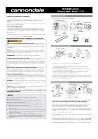
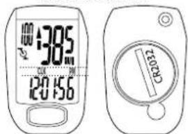
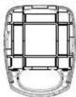
COMPUTER PARTS
Check the following components before installation:
IQ400 COMPUTER UNIT
(front)
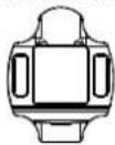
MOUNTING BRACKET
CKET
(back)(front)
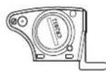
WIRELESS SPEED & CADENCE SENSOR
(back)(front)
CADENCE MAGNET

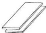
MOUNTING PAD

SENSOR
STABILIZING PADS (X2)

OKE MAGNET
COMPUTER INSTALLATION
The computer unit can be mounted on a bicycle handlebar or stem.
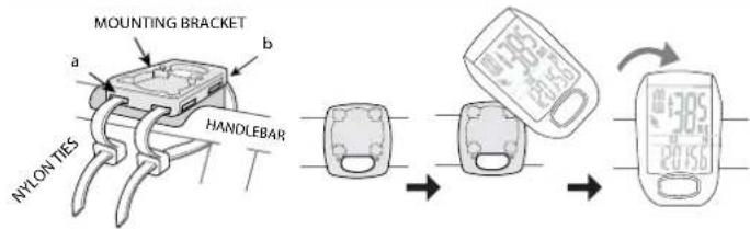
- To mount the bracket, insert two nylon ties through the mounting bracket slots. (a) - handlebar slots, (b) stem slots
- Insert the rubber pad into back of mount bracket for handlebar or stem by aligning slots in the back of the mount with the pad.
- Position the pad/bracket onto the handlebar or stem and tighten both nylon ties securely. Carefully snap tie ends 1-2mm from tie head.
To mount the computer onto the bracket, position it into the bracket at a 45 degree angle, hold down and rotate the computer unit clockwise to lock it in place. To remove it, rotate the computer counter-clockwise and lift it off.
SENSOR INSTALLATION
-
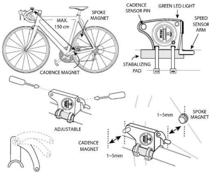
Loosen (DO NOT REMOVE) the screw on the adjustable Speed Sensor arm. Position the sensor on the top of the non-drive chainstay within 150 mm of the computer. The Cadence Sensor pin and battery door must point out toward the crank arm as shown.
-
Pass the two cable ties through the sensor mounting holes and loosely mount the sensor body to the non-drive side chainstay (do not fully tighten the cable ties at this point). Install the sensor stabilizing pad between the chainstay and sensor.
- Secure the sensor to the non-drive side chainstay with 2 nylon ties. Loosely install the sensor magnet to one of the spokes of the rear wheel. Make sure the silver side of the magnet faces toward the sensor arm.
Adjust the position of the magnet, sensor arm and sensor together so that the magnet passes by the full length of the sensor arm and 1-2 mm separates the magnet and sensor arm.
4. Loosely mount the Cadence Magnet to the inside of the crank arm using 1 of the nylon ties. Make sure the word "Sensor" faces toward the Cadence Sensor pin and a small piece of stabilizing pad is installed between the Cadence Magnet and the crank arm.
IMPORTANT: Proper adjustment of the clearances between magnets and sensors must be accurate for proper computer function. There are multiple ways to make accurate adjustments and requires care when setting up the sensors.
- Set the Speed Sensor-to-magnet and Cadence Sensor-to-magnet gaps by tilting the sensor toward or away from pickup zone. Adjust the position of the Cadence Sensor pin and Speed Sensor arm as needed - make sure to loosen or tighten the screw on the front edge of the sensor body when adjusting the Cadence Sensor pin. The maximum distance between the speed sensor and magnet on the spoke is 5 mm. The maximum distance between the cadence sensor and magnet on the crank arm is 5 mm.
- When set, draw the nylon ties tight but do NOT fully tighten. This will allow for minor adjustments after the computer setup is complete.
SETTING CALORIES BURNED (KCAL)
This computer can estimate calories burned while riding. The estimate is based on weight, gender, time ridden and average speed. IMPORTANT: The estimate is truly an estimate. Actual calories burned will vary depending on many variables the computer does not calculate such as heart rate.
- Press FUNCTION until the 'KCAL' displays.
2 Press and hold SET for >3 seconds to begin programming. - Press SET to select gender"MALE"or "FEMALE".
- Press FUNCTION to store gender.
- Press SET to change weight unit "Kg" or "Lb".
- Press FUNCTION to begin entering your weight in unit selected.
- Press or hold Set to change the weight. Range: 0 - 150 Kg, 0-330 Lb.
- Press and hold the Function for 3 seconds to exit programming.
RESETTING THE ODOMETER (ODO)
If the battery is replaced, it is possible to update the odometer to the mileage on your bike after replacing the battery.
- Press FUNCTION until the "ODO" displays.
- Press and hold SET for >3 seconds to begin programming.
- Press FUNCTION until '00000' (five zeros) and 'ODO' appears on the screen
- Press SET to change the appropriate numbers. Press FUNCTION to change cursor position.
- Repeat step 4 until the odometer is set.
- Press and hold FUNCTION for 3 seconds to exit programming.
- Verify the computer shows speed and cadence. If not, you may have to complete the Final Set Up steps shown in these instructions.
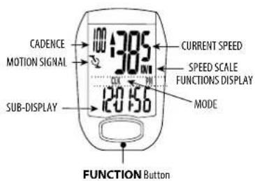
Main DiSplaY and FunctiOnS
To begin using the computer, simply press the FUNCTION button. Following installation, the computer is activated automatically by a rotating wheel.
There are 2 power saving modes - 50% savings if no movement after 5 minutes, 100% power savings after 30 minutes.
Press the SET button to exit the power saving modes prior to using the computer.
Press the FUNCTION button, to switch the computer through the following functions:
"CLK" - Clock feature, in 12/24 hr format
TM Time ridden for 1 ride
AVS-Average speed for 1 ride
"MXS" Maximum speed for 1 ride
"A.CAD" - Average cadence per minute for 1 ride
"MCAD" - Maximum cadence for 1 ride
"DST" - Distance ridden for 1 ride
"ODO" - Total miles ridden for all rides
^KCAL - Calories burned (estimate) for 1 ride
DAILY - Distance ridden in the past 24 hours
"SCAN" - Computer display scans all functions. Press the FUNCTION button to stop
scanning.
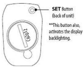
To turn on the backlight, press and release the SET button. The backlight will stay on for three (3) seconds.
TM, AVS, MXS, DST, and KCAL are recorded automatically as soon as the wheel moves. A CAD and M CAD are automatically recorded as soon as the crank moves. Recording stops if the wheel stops. Cadence recording stops if the crank stops. To clear this information, press and hold the SET button in the "IM" mode.
GENERAL NOTES FOR PROGRAMMING ALL FUNCTIONS:
- Press and hold SET for 3 seconds to begin programming a function.
- Press the SET to change the value of a selected field. Press/hold SET to change value rapidly.
Press the FUNCTION button to move the cursor to the next field.
Press and hold the FUNCTION button for 3 seconds to exit programming.
SETTING THE CLOCK (CLK)
- Press FUNCTION until the "CLK" function shows.
- Press and hold SET for >3 seconds to begin programming.
- Press SET to change to '12H' or '24H' hour mode.
- Press the FUNCTION to move the cursor to the hour field
- Press SET hour.
- Repeat steps 4 and 5 to set Minutes and Seconds.
- Press and hold the FUNCTION button for 3 seconds to exit programming.
SETTING THE WHEEL SIZE
- Press FUNCTION until the 'ODO' displays.
- Press and hold SET for >3 seconds to begin programming.
- Press SET to change to "KM/H" or "M/H"
- Determine your Tire Size then find the corresponding L (mm) in the chart below.
- Press FUNCTION to move the cursor to the first field.
- Press SET to change the 1st digit of 4 numbers for the L (mm).
Repeat steps 5 and 6 until the proper L (mm) is entered.
- Press and hold FUNCTION for 3 seconds to exit programming.
- Verify the computer shows speed and cadence. If not, you may have to complete the Final Set Up steps shown in these instructions.
| L(mm) | Tire Size I (mm) Tire Size I (mm) | ||||
| 24 X 1.75 1890 | 27 X 1-3/8 2169 | ||||
| 24 X 2.00 1925 | 50 X 20C 1938 | ||||
| 24 X 2.125 1965 | 550 X 23C 1944 | ||||
| 26 X 7/8 1970 | 60 X 35A 2000 | ||||
| 26 X 1059 | 650 X 38A 215 | ||||
| 26 X 1650 | 650 X 38B 2105 | ||||
| 26 X 1.25 1933 | 700 X 18C 2070 | ||||
| Tire Size I (mm) | X 1-1/8 1970 | 7000 X 19C 7080 | |||
| 14 X 1.50 1070 | X 1-3/8 708 | 7000 X 70C 7086 | |||
| 14 X 1.75 1055 | X 1-1/2 2180 | 7000 X 23C 2096 | |||
| 16 X 1.50 1165 | X 1-40 2000 | 7000 X 25C 2105 | |||
| 16 X 1.75 1195 | X 1-50 7010 | 7000 X 78C 2136 | |||
| 18 X 1.50 1340 | X 1-75 7070 | 7000 X 30C 2146 | |||
| 18 X 1.75 1350 | X 1-95 2050 | 7000 X 32C 2155 | |||
| 20 X 1.75 1515 | X 2-2,000 2050 | 700C Tubular 2130 | |||
| 20 X 1.3/8 1615 | X 2-10 2060 | 7000 X 35C 2168 | |||
| 22 X 1.5/8 1770 | X 2-125 2070 | 7000 X 38C 2180 | |||
| 22 X 1-1/2 1785 | X 2-35 2083 | 7000 X 40C 2200 | |||
| 24 X 1-1/53 22 X 3.00 2170 | 29 X 2.1 | 2288 | |||
| 24 X 3/4 tubular | 1785 | 27 X 1 | 2145 | 29 X 2.3 | 2326 |
| 24 X 1-1/8 1795 | 27 X 1-1/8 255 | ||||
| 24 X 1-1/4 1905 | 27 X 1-1/4 261 | ||||
FINAL SET UP
IMPORTANT: After the computer is programmed, final set up must be confirmed.
- Install the computer onto the mounting bracket.
- Gently spin the wheel. Verify the Speed and Cadence magnets to not hit the sensor arms.
- Gently spin the cranks then check the display to verify the Speed and Cadence are showing on the computer. The green LED light on the sensor should also flash verifying proper set up. If either is not appearing on the screen and the LED is not flashing, adjust the gaps between magnets. Spin the cranks again.
- If the speed or cadence do not appear on the screen after steps 1-3 are complete, you may have to pair the sensor to the computer again.
4a. With the computer mounted, press and hold the SET and FUNCTION buttons at the same time for 5 seconds.
4b. Turn the cranks. A 2 digit ID code between "00-63" will appear on the screen. Press the SET button. Turn the cranks when the Sub-Display flashes lines "---". Continue turning the cranks for 10 seconds. Pairing is complete when the computer returns to the home screen.
4c. If "ERR" appears in the screen, repeat steps 1 through 4b. - When all setup including sensors and magnets is complete, draw the nylon ties securely. Carefully snip the tie ends 1-2mm from tie head.
BATTERY REPLACEMENT
Remove the computer from the handlebar mount. Use a coin to unscrew the battery door. Turn counter-clockwise. Remove the old battery. Place a new battery (CR2032) into the computer with the positive ^+ marking of the battery facing up. Replace the battery door.
Follow these steps for replacing the sensor battery (CR2032).
Verify the computer shows speed and cadence. If not, you may have to complete the Final Set Up steps shown in these instructions.
IQ400 Specifications
Operating Temperature 0^ 40^,(32^ 104^)
Storage Temperature -10°C~50°C, (14°F~122°F)
Battery 3 volt lithium, CR2032 cell
Weight 30.6 grams
Timer Range: 0~29 (hour): 59 (minute): 59 (second)
Current Speed Range: 0 ~ 99.9 KM/ 0~62 Mile
Average Speed Range: 0 99.9KM / 0 62 Mile
MAX Speed Range: 0 - 99.9 KM/ 0 - 62 Mile
(Trip) Distance Range: 0~999.99 KM/0~600 Mile
Odometer Range: 0 99999KM/0 62000 Mile
TROUBLESHOOTING
| CONDITION | ACTION |
| Wheel moving but current speed does not appear | Check/adjust sensor and magnet gap. Battery is low -> replace |
| “ERR01” appears on display | Battery low -> replace |
| “ERR” appears on display | Interference from another electronic device-> turn off or move electronic device |
| Display is blank, very light or black | Battery low -> replace. Computer too hot -> move to cool area. |
| Display changes slowly | Computer too cold -> move to warm area |
CANNONDALE CONTACT INFORMATION
| CANNONDALE USA Cycling Sports Group, Inc. 172 Friendship Road, Bedford, Pennsylvania, 15522, USA (Voice): 1-800 BKE USA (Fax): 814-623-6173 custserv@cyclingsportsgroup.com | CANNONDALE EUROPE Cycling Sports Group Europe, B.V. mail: Postbus 5100 visits: Hanzepoort 27 7570 GC, Oldenzaal, Netherlands (Voice): +41 61.4879380 (Fax): 31-5415-14240 servicedeskeuropa@cyclingsportsgroup.com |
| CANNONDALE AUSTRALIA Cycling Sports Group Australia Pty Limited Unit B, 31-41 Bridge Road Stannmore, NSW 2048, Australia (Voice): 61-2-85954444 (Fax): 61-2-85954499 cannondale@cyclingsportsgroup.com.au | CANNONDALE JAPAN Namba Sumiso Building 9F, 4-19, Minami Horie I-chome, Nishi-ku, Osaka 550-0015, Japan (Voice): 06-6110-9390 (Fax): 06-6110-9361 cjcustserv@cannondale.com |
| CANNONDALE UK Cycling Sports Group Vantage Way, The Fulcrum, Poole, Dorset, BH12 4NU (Voice): -44 (0)1202 732288 (Fax): +44 (0)1202 723366 sales@cyclingsportsgroup.co.uk |
MERCID'AVOIR CHOISI UN PRODUIT CANNONDALE!
| CANNONDALE USA Cycling Sports Group, Inc. 172 Friendship Road, Bedford, Pennsylvania, 15522, USA (Voice): 1.800 BKE USA (Fax): 814-623-6173 custserv@cyclingsportsgroup.com | CANNONDALE EUROPE Cycling Sports Group Europe, B.V. mail: Postbus 5103 visits: Hanzepoort 27 7570 GC, Oldenzaal, Netherlands (Voice): +41 61.4879380 (Fax): 31-5410-14210 servicedeskeuropa@cyclingsportsgroup.com |
| CANNONDALE AUSTRALIA Cycling Sports Group Australia Pty Limited Unit 8, 31-41 Bridge Road Stanmore, NSW 2048, Australia (Voice): 61-2-85954444 (Fax): 61-2-85954499 cannondale@cyclingsportsgroup.com.au | CANNONDALE JAPAN Namba Sumatra Building 9F, 4-19, Minami Horei 1-chome, Nishi-ku, Osaka 550-0015, Japan (Voice): 06-6110-9390 (Fax): 06-6110-9361 cjustserv@cannoncale.com |
| CANNONDALE UK Cycling Sports Group Vantage Way, The Ficulum, Poole, Dorset, BH12 4NU (Voice): +44 (01)202 732288 (Fax): +44 (01)202 723366 sales@cyclingsportsgroup.co.uk |