IQ300 - Counter CANNONDALE - Free user manual and instructions
Find the device manual for free IQ300 CANNONDALE in PDF.

User questions about IQ300 CANNONDALE
0 question about this device. Answer the ones you know or ask your own.
Ask a new question about this device
Download the instructions for your Counter in PDF format for free! Find your manual IQ300 - CANNONDALE and take your electronic device back in hand. On this page are published all the documents necessary for the use of your device. IQ300 by CANNONDALE.
USER MANUAL IQ300 CANNONDALE
THANK YOU FOR PURCHASING A CANNONDALE
Congratulations on your purchase of a Cannondale IQ Series computer. Proper setup and operation will greatly enhance this product's usefulness and your enjoyment.
Please follow all Warnings and read all sections of this manual carefully and become fully familiar with its operation before using it.
Along with this manual, your key source of information and assistance is the shop where you purchased this product. Your local Authorized Cannondale Retailer is your primary contact to discuss service and adjustment to this product, instruction in its use, and any warranty questions.
To find an Authorized Cannondale Retailer closest to you, call 1-800-BIKE-USA. Or you can use our dealer locator at our website www.cannondale.com.
IMPORTANT INFORMATION FOR ALL CANNONDALE CYCLING COMPUTERS

WARNINGS
WIRELESS COMPUTER MODELS (IQ200, IQ300, and IQ400) - People with medical/implanted electronic equipment or devices such as heart pacemakers, EKG equipment, etc. must not use wireless cycle computers due to possible risk of interference with the medical devices.
EXERCISE - Adults with health problems (such as heart disease, diabetes or obesity) or those at high risk, men over age 40 and women over age 50 or pregnant should talk with their doctor before starting an exercise program.
INTENDED USE: For bicycle use only. Not for use on any motorized vehicle.
OPERATE COMPUTER ONLY WHEN NOT RIDING: Failure to pay attention to the road, trail, traffic or your surroundings could result in an accident, with risk of serious injury, paralysis or death. You must focus on riding, not your computer. Learn computer operations, and do all possible computer operations when not riding. For any operations you choose to perform while riding, choose a time and place where this distraction has less risk.
MAKE SURE ALL COMPUTER PARTS ARE INSTALLED PROPERLY: The computer must not interfere with the bicycle controls and your ability to use them. Mount the computer according to the directions in this instruction manual. See your Authorized Cannondale Retailer if you have any trouble installing or maintaining your computer.
CHECK FOR DAMAGE REGULARLY: Regularly check the position, alignment, and condition of the spoke magnet, wireless sensor, cadence sensor, sensor and sensor wire to make sure they are secure, aligned and in good condition. Make sure nothing is loose and there are no worn or damaged parts.
BATTERIES: Use only battery size and type specified on the unit. Do not leave any batteries in reach of children, and dispose of them correctly. If a battery is swallowed, consult a doctor immediately.
NOT A TOY: Keep this computer and associated parts including the battery away from children. Small parts could be swallowed.
YOU CAN BE SEVERELY INJURED, PARALYZED OR KILLED IN AN ACCIDENT IF YOU IGNORE THESE WARNINGS.
NOTICE
■ This product is rain-proof only. Do not submerge or power wash.
■ Do not disassemble the unit.
■ Mount the computer according to the directions in this instruction manual.
■ Avoid direct impact to the computer unit.
■ Avoid using the computer unit in or near strong electromagnetic fields such as high-voltage power lines or other transmitters.
■ Clean the unit with a mild detergent and a soft dry cloth. Never use any kind of solvent or alcohol.
■ To prevent damage caused by battery leakage, remove the batteries before storage or long period of non-use. Do not reverse battery installation. Observe positive (+) and negative (-) markings.
■ WIRELESS MODELS (IQ200, IQ300, IQ400) Wireless computer uses an analog wireless signal. It is not digitally coded but uses technology to lower the chance of interference with circuitry used in other electronic devices such as lights, phones, computers, etc.
COMPUTER PARTS
Check the following components before installation:
IQ300 COMPUTER UNIT
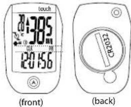
text_image
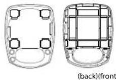
touch 385 120 156 (front) CR052 (back)MOUNTING BRACKET
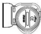
WIRELESS SENSOR

MOUNTING PAD

SPOKE MAGNET

COMPUTER INSTALLATION
text_image
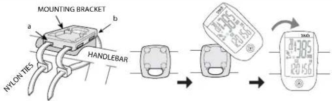
MOUNTING BRACKET a b NYLON TIES HANDLEBAR 24.05 28.56 24.05 28.56 24.05 28.56The computer unit can be mounted on a bicycle handlebar or stem.
- To mount the bracket, insert two nylon ties through the mounting bracket slots. (a) - handlebar slots, (b) stem slots
- Insert the rubber pad into back of mount bracket for handlebar or stem by aligning slots in the back of the mount with the pad.
- Position the pad/bracket onto the handlebar or stem and tighten both nylon ties securely. Carefully snip tie ends 1-2mm from tie head.
To mount the computer onto the bracket, position it into the bracket at a 45 degree angle, hold down and rotate the computer unit clockwise to lock it in place. To remove it, rotate the computer counter-clockwise and lift it off.
SENSOR INSTALLATION
text_image
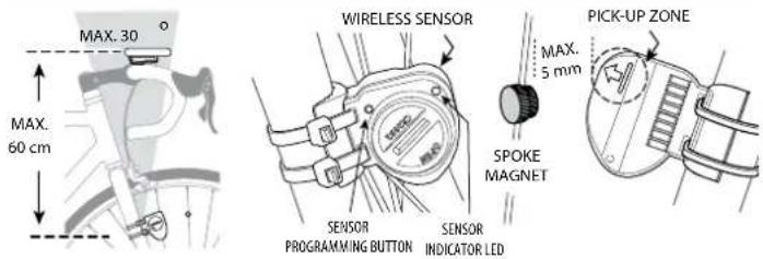
MAX. 30 ° MAX. 60 cm WIRELESS SENSOR SENSOR PROGRAMMING BUTTON SENSOR INDICATOR LED SPOKE MAGNET PICK-UP ZONE MAX. 5 mm- Position the sensor on the front of the right fork leg within 60 cm of the computer. The battery door must face out with the tear drop shape pointing down shown.
-
Pass the two cable ties through the sensor mounting holes and loosely mount the fork sensor body to the left fork blade (do not fully tighten the cable ties at this point). Loosely install the sensor magnet to one of the spokes of the front wheel. Adjust the position of the magnet and sensor together so that the magnet is aligned with the line on the bottom edge of the sensor and 1.2 mm separates the two parts and tighten both parts in place. Secure the sensor to the fork leg with two nylon ties.
-
Install the magnet onto a spoke so the magnet will pass over the sensor in the pickup zone when the wheel is rotated.
-
Set the sensor-to-magnet gap by tilting the sensor toward or away from pickup zone. The maximum distance between the speed sensor and magnet on the spoke is 5 mm.
-
When set, draw the nylon ties securely. Carefully snip the tie ends 1-2mm from tie head.
MAIN DISPLAY AND FUNCTIONS
text_image
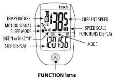
touch TEMPERATURE MOTION SIGNAL SLEEP MODE BIKE "I or BIKE "II" SUB-DISPLAY CURRENT SPEED SPEED SCALE FUNCTIONS DISPLAY MODE 120 156 FUNCTION Button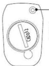
SET Button (back of unit)
**This button also, activates the display backlighting.
To begin using the computer, simply press the FUNCTION button. Following installation, the computer is activated automatically by a rotating wheel.
There are 2 power saving modes - 50% savings if no movement after 5 minutes, 100% power savings after 30 minutes.
Press the SET button to exit the power saving modes prior to using the computer.
Press the FUNCTION button, to switch the computer through the following functions:
"CLK" – Clock feature, in 12/24 hr format
"TM" - Time ridden for 1 ride
"AVS" – Average speed for 1 ride
"MXS" - Maximum speed for 1 ride
"DST" - Distance ridden for 1 ride
"ODO" – Total miles ridden for all rides
"KCAL" – Calories burned (estimate) for 1 ride
"DAILY" -- Distance ridden in the past 24 hours
"ODO 1" -- Total miles for all rides, bike 1 "①
"ODO 2" - Total miles for all rides, bike 2"
To turn on the backlight, press and release the SET button. The backlight will stay on for three (3) seconds.
"TM, AVS, MXS, DST, and KCAL" are recorded automatically as soon as the wheel moves. Recording stops if the wheel stops. To clear this information, press and hold the SET button in the "TM" mode.
GENERAL NOTES FOR PROGRAMMING ALL FUNCTIONS:
• Press and hold SET for 3 seconds to begin programming a function.
- Press the SET to change the value of a selected field. Press/hold SET to change value rapidly.
- Press the FUNCTION button to move the cursor to the next field.
• Press and hold the FUNCTION button for 3 seconds to exit programming.
SETTING THE CLOCK (CLK)
- Press FUNCTION until the "CLK" function shows.
- Press and hold SET for >3 seconds to begin programming.
- Press SET to change to "12H" or "24H" hour mode.
- Press the FUNCTION to move the cursor to the hour field
- Press SET hour.
- Repeat steps 4 and 5 to set Minutes and Seconds.
- Press and hold the FUNCTION button for 3 seconds to exit programming.
SETTING THE WHEEL SIZE
NOTE: This computer can record information for 2 bikes with different wheel sizes. This allows you to use 1 computer for 2 bikes. Shortly after the wheel rotates, the computer automatically knows which bike is being used then provides accurate information for speed and mileage. A mounting kit for a 2nd bike is sold separately. The following steps only need to be done once.
To start programming:
- Press FUNCTION until "ODO" displays.
- Press and hold SET for >3 seconds to begin programming.
- Press SET to change to "KM/H" or "M/H"
To program the computer for bike #1:
- Determine your Tire Size then find the corresponding L (mm) in the chart below.
- Press SET to select bike 1 Ⓓ
- Press FUNCTION to move the cursor to the first field.
- Press SET to change the 1st digit of 4 numbers for the L (mm).
Repeat steps 6 and 7 until the proper L (mm) is entered.
If you will use this computer for 2 bikes, continue to step 8.
If you will use it for only 1 bike, continue to step 10.
To program the computer for bike #2:
- Determine your Tire Size then find the corresponding L (mm) in the chart below.
- Press FUNCTION to select bike 2 °
Repeat steps 6 and 7 until the proper L (mm) is entered.
- Press and hold FUNCTION for 3 seconds to exit programming.
| Tire Size L (mm) Tire Size L (mm) | |||||
| 24 X 1.75 1890 | 27 X 1-3/5 2169 | ||||
| 24 X 2.00 1925 | 650 X 20C 1938 | ||||
| 24 X 2.125 1965 | 650 X 23C 1944 | ||||
| 26 X 7/8 1920 | 650 X 35A 2090 | ||||
| 26 X 1(59) 1913 | 650 X 38A 2175 | ||||
| 26 X 1(65) 1952 | 650 X 38B 2163 | ||||
| 26 X 1.25 1953 | 700 X 18C 2070 | ||||
| Tire Size L (mm) | 26 X 1-1/8 19 | 70 700 X 19C 2080 | |||
| 14 X 1.50 1020 | 26 X 1 3/8 20 | 88 700 X 20C 2086 | |||
| 14 x 1.75 1055 | 26 x 1 1/2 210 | 90 700 X 23C 2096 | |||
| 16 X 1.50 1185 | 26 X 1.40 200 | 6 700 X 25C 2105 | |||
| 16 X 1.75 1195 | 26 X 1.50 201 | 4 700 X 28C 2136 | |||
| 18 X 1.50 1340 | 26 X 1.75 202 | 6 700 X 30C 2146 | |||
| 18 X 1.75 1350 | 26 X 1.95 205 | 8 700 X 32C 2155 | |||
| 20 X 1.75 | 15 5 | 26 X 2.00 | 2055 | 700C Tubular | 2130 |
| 20 X 1 3/8 1615 | 26 X 2.10 206 | 8 700 X 35C 2169 | |||
| 22 X 1-3/8 1770 | 26 X 2.125 20 | 90 700 X 38C 2180 | |||
| 22 X 1-1/2 1785 | 26 X 2.35 208 | 8 700 X 40C 2200 | |||
| 24 X 1 | 1753 | 26 X 3.00 | 2170 | 29 X 2.1 | 2288 |
| 24 X 3/4 Tubular | 1785 | 27 X 1 | 2145 | 29 X 2.3 | 2326 |
| 24 x 1-1/8 1795 | 27 X 1-1/8 215 | ||||
| 24 X 1-1/4 1905 | 27 X 1-1/4 2161 | ||||
PROGRAMMING THE SENSOR
text_image
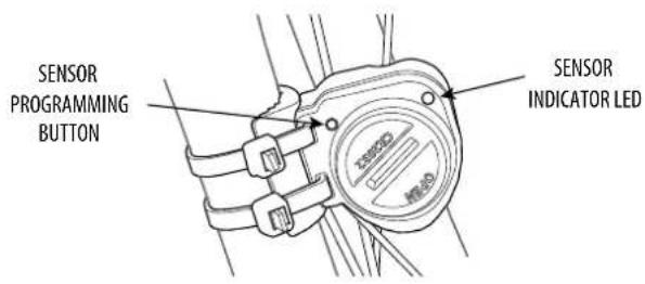
SENSOR PROGRAMMING BUTTON SENSOR INDICATOR LEDNOTE: These steps are only required if using the computer with a 2nd bike and only need to be done once. Complete these steps after the computer is programmed and the sensor is installed.
- Install the computer on Bike 2.
- Press the blue SENSOR PROGRAMMING BUTTON on the back of the SENSOR INDICATOR LED flashes. Release the button.
- Lift the front wheel off the ground and spin it. The bike 1 icon will switch to the bike 2 icon and begin recording information for bike 2.
- Verify final set up for bike 2 by pressing the blue SENSOR PROGRAMMING BUTTON. The LED will flash twice for bike 2.
- To verify final set up for bike 1, reinstall the computer on bike 1. Lift and spin the front wheel to start the computer. Stop the wheel then press the blue SENSOR PROGRAMMING BUTTON. The SENSOR INDICATOR LED will flash 1 time to verify proper function with bike 1.
SETTING CALORIES BURNED (KCAL)
This computer can estimate calories burned while riding. The estimate is based on weight, gender, time ridden and average speed. IMPORTANT: The estimate is truly an estimate. Actual calories burned will vary depending on many variables the computer does not calculate such as heart rate.
- Press FUNCTION until the "KCAL" displays.
2 Press and hold SET for >3 seconds to begin programming. - Press SET to select gender "MALE" or "FEMALE".
- Press FUNCTION to store gender.
- Press SET to change weight unit "Kg" or "Lb".
- Press FUNCTION to begin entering your weight in unit selected.
- Press or hold Set to change the weight. Range: 0 \~ 150 Kg, 0-330 Lb.
- Press and hold the Function for 3 seconds to exit programming.
RESETTING THE ODOMETER (ODO)
If the battery is replaced, it is possible to update the odometer to the mileage on your bike after replacing the battery.
- Press FUNCTION until the "ODO" displays.
- Press and hold SET for >3 seconds to begin programming.
- Press FUNCTION until "00000" (five zeros) and "ODO" appears on the screen
- Press SET to change the appropriate numbers. Press FUNCTION to change cursor position.
- Repeat step 4 until the odometer is set.
- Press and hold FUNCTION for 3 seconds to exit programming.
SETTING THE TEMPERATURE
- Press FUNCTION until "ODO" displays.
- Press and hold SET for >3 seconds to begin programming.
- Press FUNCTION repeatedly until "TEMP" displays. Press SET to change Fahrenheit (F) or Celsius (C)
- Press and hold FUNCTION for 3 seconds to exit programming.
BATTERY REPLACEMENT
Remove the computer from the handlebar mount. Use a coin to unscrew the battery door. Turn counter clockwise. Remove the old battery. Place a new battery (CR2032) into the computer with the positive ± marking of the battery facing up. Replace the battery door.
Follow these steps for replacing the sensor battery (CR2032).
IQ300 Specifications
Operating Temperature 0°C \~ 40°C, (32°F \~ 104°F)
Storage Temperature -10°C \~ 50°C, (14°F \~ 122°F)
Battery 3 volt lithium, CR2032 cell
Weight 30.6 grams
Timer Range: 0\~29 (hour): 59 (minute): 59 (second)
Current Speed Range: 0 \~ 99.9 KM/ 0\~62 Mile
Average Speed Range: 0\~99.9 KM/0\~62 Mile
MAX Speed Range: 0 \~ 99.9 KM/0 \~ 62 Mile
(Trip) Distance Range: 0 - 999.99 KM/ 0-600 Mile
Odometer Range: 0 \~ 99999 KM/0 \~ 62000 Mile
TROUBLESHOOTING
| CONDITION ACTION | |
| Wheel moving but current speed does not appear | Check/adjust sensor and magnet gap.Battery is low -> replace |
| "ERR01" appears on display Battery low -> replace | |
| "ERR" appears on display | Interference from another electronic device > turn off or move electronic device |
| Display is blank, very light or black Battery low -> replace.Computer too hot -> move to cool area. | |
| Display changes slowly | Computer too cold -> move to warm area |
NOTE: Touch feature is activated by finger pressure. If gloves are to thick, such as winter gloves, the FUNCTION button may not be activated and require more pressure.
NOTE: The computer uses a pencil tip sized free-floating sensor for auto on/off features. If you hear a rattling noise during excessive vibration, it is normal and the function will not be effected.
CANNONDALE CONTACT INFORMATION
| CANNONDALE USACycling Sports Group, Inc.172 Friendship Road,Bedford, Pennsylvania, 15322 , USA(Voice): 1-800-BIKE-USAI(Fax): 814 623 6173custserv@cyclingsportsgroup.com | CANNONDALE EUROPECycling Sports Group Europe, B.V.mail: Postbus 5100visits: Hanzepoor, 27/570 GC, Oldenzaal, Netherlands(Voice): 1 41 61.4879380(fax): 31-5415-14210servicedeskeurope@cyclingsportsgroup.com |
| CANNONDALE AUSTRALIACycling Sports Group Australia Pty LimitedUnit B, 31-41 Bridge RoadStanmore, NSW 2048, Australia(Voice): 61-2-85954444(fax): 61-2-85954499cannondale@cyclingsportsgroup.com.au | CANNONDALE JAPANNamba Sumiso Building 9F,4-19, Minami Horie 1-chome,Nishi-ku, Osaka 550-0015, Japan(Voice): 06-6110-9390(fax): 06-6110-9361jcustserv@cannondale.com |
| CANNONDALE UKCycling Sports GroupVantage Way, The Fulcrum,Poole, Dorset, 8H12 4NU(Voice): -44 (0)1202 732288(Fax): +44 (0)1202 723366sales@cyclingsportsgroup.co.uk |