KH 17217 E - Basket AMICA - Free user manual and instructions
Find the device manual for free KH 17217 E AMICA in PDF.
Download the instructions for your Basket in PDF format for free! Find your manual KH 17217 E - AMICA and take your electronic device back in hand. On this page are published all the documents necessary for the use of your device. KH 17217 E by AMICA.
USER MANUAL KH 17217 E AMICA
You are now a user of a kitchen extractor hood. This hood has been designed and manufactured spe- cially with a view to satisfying your expectations and it will certainly constitute a tting element of a modern kitchen. The modern structural solutions and the newest technologies used in production of this hood guarantee its high effectiveness and good appearance. Please read these instructions carefully before installing the hood. They will help you avoid mistakes during installation and operation of the hood. We wish you a lot of satisfaction from choosing our kitchen extractor hood. DEAR CUSTOMER! THANK YOU FOR PURCHASING AN AMICA APPLIANCE Symbols appearing in these instructions have the following meaning: This indicates actions than must not be performed by the user. Risks resulting from improper operation of the appliance. Activities that must be performed by a qualied technician. Important information concerning proper operation of the appliance and your perso- nal safety. Tips on how to use the appliance.
Information on how to protect the environ- ment. The appliance is intended for household use only. The manufacturer reserves the right to introduce changes which do not affect the operation of the appliance.9
lThe manufacturer will accept no responsibility for any damage due to installation or operation not conforming to these instructionsi l Cooker hood is desi- gned to remove cooking odours. Do not use co- oker hood for other pur- poses. l Connect the cooker hood operating in extraction mode to a suitable ventilation duct (do NOT connect the cooker to smoke or ue gas ducts, which are in use). It requires installa- tion of the air extraction duct to the outside. The duct length (typically 120 or 150mm in diame- ter) should not exceed 4-5 m. The air exhaust duct is also required for telescopic and under furniture cooker hoods operating in air recircu- lation mode. l Cooker hood operating in air recirculation mode requires the installation of an activated charcoal lter. In this case, instal- ling an extractor duct is not required, however it is recommended to in- stall an air guide vane. (chimney cooker hoods only).
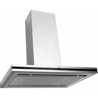
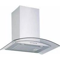
l The cooker hood featu- res independent lighting and exhaust fan that can be operated at one of several speeds. l Depending on the type, the hood is designed to be permanently atta- ched to a vertical wall over a gas or electric stove (chimney and universal hoods); on the ceiling over a gas or electric stove (island hoods); on the vertical built in furniture over a gas or electric stove (telescopic and built-in hoods). Before instal- ling, make sure that the wall/ceiling structure is strong enough to su- spend the hood. Some hoods are very heavy.10 l For details of the instal- lation distance above an electric hob please re- fer to product technical sheet If the installation instructions of the gas cooker specify a greater distance, this must be taken into account (Fig. 1a/b/c). l Do not leave an open ame under the hood. When the pots are re- moved from the burner, set the minimum a- me. Always make sure that the ame does not extend outside the pot, because it causes unwanted loss of ener- gy and a dangerous concentration of heat. l Any food cooked in fat shall be constantly monitored, since over- heated fat can ignite very easily. l Pull the plug of the power cord from a wall socket before any lter cleaning or repair op- eration. l The textile grease l- ter should be replaced, and the aluminium lter should be cleaned at least every one month in connection with the existing re danger (saturated fat is very ammable). l If any other non-electric devices are used in the same room as the hood (e.g. liquid fuel ovens, ow-through or volu- metric water heaters), it is necessary to provide appropriate ventilation (air supply). Safe op- eration is possible when during simultaneous op- eration of the hood and combustion devices de- pendent on air supply the negative pressure of not more than 0.004 milibar is maintained at the location of these devices inside the room (this point does not ap- ply when the hood is used as an odour ab- sorber). l Do not abut against the hood
GUIDELINES CONCERNING THE SAFETY OF USE11
l The hood should be frequently cleaned in- side and on the outside surfaces (at least once a month). See “Clean- ing section” in this man- ual. l If the power wire gets broken, it should be re- placed with a new one in a specialist repair shop. l Make sure the ap- pliance can be easily disconnected from the mains, either by pulling the plug out of the mains socket, or by switching the two-pole switch off. l This appliance is not intended for use by per- sons (including children) with reduced physical, sensory or mental capa- bilities, or lack of expe- rience and knowledge, unless they have been given supervision or instruction concerning use of the appliance by a person responsible for their safety. l Children should be su- pervised to ensure that they do not play with the appliance. l Check if the voltage indicated on the rating plate corresponds to the local power supply parameters. l Before installing un- wind and straighten the power cord. l Warning! The pack- aging materials (poly- ethylene bags, small pieces of foamed poly- styrene etc.) should be kept away from children while unpacking. l NOTE: Before con- necting the hood to the mains power sup- ply always check that the power cord is prop- erly installed and is not trapped by the appli- ance. It is recommend- ed to make sure the hood operates correctly before installation. l Never use the hood wi- thout effectively moun- ted grating! l The aming of foods beneath the hood itself is severely prohibited. l With regards to the technical and safety measures to be adop- ted for fume discharging it is important to closely follow the regulations provided by the local authorities.
GUIDELINES CONCERNING THE SAFETY OF USE12
l WARNING! Failure to install the screws or xing device in accor- dance with these in- structions may result in electrical hazardsii
GUIDELINES CONCERNING THE SAFETY OF USE13
INSTALLATION Elements kitchen hood consists of the following elements (Fig. 2...) Installation Step-by-step appliance installation is shown on Fig.
Setting the air extractor mode of operation of the hood In the extractor mode air is discharged to the out- side by a special conduit. In that setting any carbon lters shall be removed. The hood should be con- nected to the opening discharging air to the outside by means of a rigid or exible conduit of 120 mm diameter, which should be purchased in a shop selling installation materials. A qualied installer should be commissioned to make the connection. Setting the odour absorber mode of operation of the hood In this option ltered air returns to the room through openings in the front of the hood. In this setting it is necessary to install the carbon lter. It is recommended to install the air guide (availability depending on model). In some universal hoods you need to switch lever inside the hood (Fig. 8) to switch between the extraction and air recirculation modes. The cle- aned air is returned to the room through the holes in the top of the unit. Furniture and telescopic cooker hoods operating in air recirculation mode require installation of the exhaust duct. The other end of the duct should be directed to the room as it will discharge ltered air. Fan speeds The lowest and medium speeds should be used under normal conditions and with low concentration of fumes. The maximum speed should be used in case of high concentration of kitchen fumes, e.g. during frying or grilling. INSTALLATION15
OPERATION AND MAINTENANCE
Use control panel to control your cooker hood (Fig. 4a / 4b) - “-” and “+” touch sensors control cooker hood fan speed in the range from 1 to 4, - “+” touch sensor increases cooker hood fan speed - “-” touch sensor reduces cooker hood fan speed - Timer touch sensor activates fan timer (max 90 min.) - Lights “L” touch sensor switches cooker hood lights on/off independently of fan operation. Press for a short time to switch on/off lights. Program function (Timer) - This cooker hood has a timer function, which controls fan operation. It can be programmed to auto- matically switch off the fan after 10 to 90 minutes in 10 minutes intervals. - In order to activate the timer function set the cooker hood fan at a required speed by pressing the “+” touch sensor and then touch the timer (clock) touch sensor. The display will show a ashing 0 to indicate that timer setup mode is activated. Now select the delay time to switch off the cooker hood fan by touching ‘’+‘’, keeping in mind that the number displayed musts be multiplied by the 10 minute interval (For example 1=10 min, 2=20 min,3=30 min, and so on) - Once the required delay time is set, conrm it by touching the timer (clock) symbol again. The dis- play will stop ashing and indicate current fan speed. A small ashing dot by the value correspond- ing to fan speed indicates that timer is counting down. To cancel the fan timer function, touch the timer (clock) sensor while the countdown timer is running. Note: The timer function must be activated within 20 seconds. If no action is taken the cooker hood will switch to normal operation mode. Electronics protected with a 250V-1.6 A fuse / quick acting (5x20 glass fuse-element). When fan and light is off the appliance will automatically go into standby after 20 seconds from the moment any sensor is touched. Power consumption of the appliance is less than 1W in standby mode In this mode, the sensor backlight remains off. touch any sensor to resume normal operation (additional sensor next to the dot on the display).
FILTER SATURATION INDICATOR
The cooker hood is equipped with an electronic lter saturation indicator: - Replace the charcoal lter – „C” is displayed (220 hours of operation), - Clean the aluminium lter – „F” is displayed (100 hours of operation), Neither of these indications affects cooker hood operation, however when C or F is shown, fan speed indication (0 to 4) is not displayed until the „C” or „F” symbol is cleared. Touch and hold timer sensor eld for about 10 seconds to clear the „C” or „F” symbols. KH 17227 E / KH 17228 E / KH 17207E / KH 17208E / KH 17210S / KH 17209S - Fig 4a KH 17217 E / KH 17218 E - Fig 4b - Press this symbol to switch off motor and light. Once the motor and/or lights are switched on, the backlight of the sensors will change to red. - Turn on/off light - sensors backlight will change to red while the light is on 1 / 2 / 3 / 4 - switching on / off the motor - step 1,2,3,4 - backlight changes to red when the motor is running in rst gear, second, third, fourth speed respectively (note: the hood after 5 ve minutes on the 4th gear will reduce speed to step 3 ) - Sets the delayed switch-off time. When activated the backlight of the timer symbol ashes. - Red backlight on this symbol indicates the necessity of replacing the lters. To erase the message press the sensor eld, the red backlight will disappear. - Boost function switches on automatically every hour for 5 minutes. Note: The main switch (OFF symbol) switches off the engine and the timer, the light needs to be turned off separately. The hood is equipped with function Standby. Control Keyboard fades after a few seconds (it indicates just off icon / off and light icon). To reactivate just touch any icon of control panel.16
OPERATION AND MAINTENANCE
Maintenance Regular maintenance and cleaning of the device will ensure faultless operation, and help extend the life of the unit. Attention should be paid to replacing grease and carbon lters according to instructions. Aluminium grease lter Cleaning For normal hood operation, aluminium grease lter should be cleaned every month in the dishwasher or by hand using a mild detergent or liquid soap. To replace: Dismantling of aluminium grease lter is shown on Figure 5. Acrylic lter is used in some models. This lter sho- uld be replaced at least once every two months or more frequently if the appliance is used intensively. Charcoal lter (only the recirculation version) Operation - Carbon lters can be used only when the hood is not connected to any ventilation duct. Filters with active carbon can absorb odours until they are saturated. They cannot be washed or re- generated and should be replaced at least every 2 months or more frequently in case of very intensive use. Replace: Dismantling of charcoal lter is shown on Figure 6. Lighting See Figure 7 for details how to replace lights. Use incandescent / halogen / LED modules of the same specication as those factory-installed in the ap- pliance. Cleaning Normal hood cleaning: l Do not use a soaked cloth, sponge, or water jet. l Do not use solvents or alcohol, as they may tarnish lacquered surfaces. l Do not use caustic substances, especially for cleaning stainless steel. l Do not use a rough or abrasive cloth. It is recommend to use a damp cloth and a neutral detergent. Aluminium lters may be washed in the dishwash- er. The colour of aluminium lters may change after several washings. This is normal and it is not nec- essary to renew the lters.17 ENVIRONMENTAL PROTECTION Recycling of the packaging Our packaging is made of envi- ronmentally friendly materials, which can be reused: l The external packaging is made of cardboard/ foil l The FCKW free shape of foamed polystyrene (PS) l Polyethylene (PE) foils and bags
ELIMINATION / DISPOSAL OF THE EU-
IPMENT If the appliance is no longer in use, cut the connecting cable off the used equip- ment before scrapping. We also recommend that the appliance is locked or render it useless so that the appliance presents no danger to children while being stored for disposal. This appliance is marked with a symbol of the crossed out waste container in conformance with the European Directive 2002/96/EC. Such marking informs that the equipment may not be kept together with other waste coming from the household af- ter the period of its use. The user is obliged to dispose of the appliance at the waste col- lection point authorised by the local author- ity. The local waste collection points, shops and communal units form an appropriate system enabling the disposal of the equip- ment. Handling the used electrical and electronic equipment and any hazardous substances contained therein in a correct manner is vi- tal to avoid damage the local natural envi- ronment. Therefore care and responsibility should always be taken in the disposal of these products Manufacturer’s Declaration The manufacturer hereby declares that this product meets the requirements of the following European directives: l Low Voltage Directive 2006/95/EC, l Electromagnetic Compatibility (EMC) Directive 2004/108/EC, l ErP Directive 2009/125/EC and has thus been marked with the symbol and been issued with a declaration of compliance made available to market regulators. Warranty Warranty service as stated on the warranty card The manufacturer shall not be held liable for any damage caused by improper use of the product.