USER MANUAL FO311 Smev
ACCENSIONE MANUALE DEL FORNO
ACCENSIONE MANUALE DEL GRILL
REGOLAZIONE DELLA FIAMMA DEL GRILL
- ACCENSIONE MANUALE DEL GRILL
WARNINGS AND SAFETY SYMBOLS
The safety symbols utilised identify possible hazards to users.
Always respect all safety warnings identified with these symbols:

WARNING
DANGER
Hazard of injury or death.

CAUTION
CAUTION
To prevent possible injury and / or damage
INDEX
INSTALLATION 13
SAFETY WARNINGS 13
CABINET APERTURE 13
INSTALLING THE FLUE 13
CONNECTING TO GAS SUPPLY 14
WIRING - CONNECTING TO ELECTRICITY SUPPLY 15
FIXTURE 15
USE 16
SAFETY WARNINGS
CONTROLS 16
BURNERS: 17
OVEN: 18
ELECTRONIC IGNITION OVEN (DEPENDING ON MODEL)
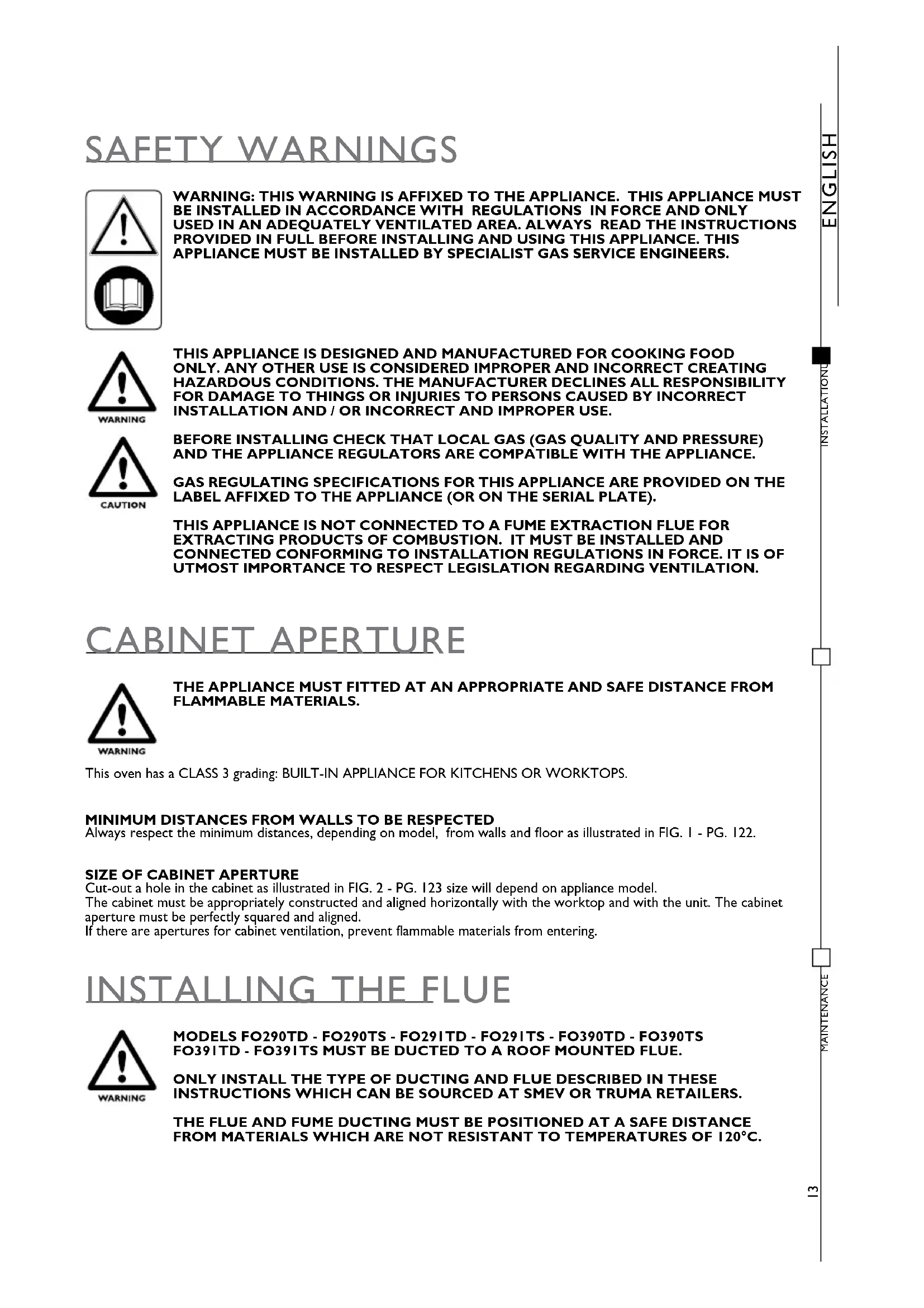
WARNING: THIS WARNING IS AFFIXED TO THE APPLIANCE. THIS APPLIANCE MUST BE INSTALLED IN ACCORDANCE WITH REGULATIONS IN FORCE AND ONLY USED IN AN ADEQUATELY VENTILATED AREA. ALWAYS READ THE INSTRUCTIONS PROVIDED IN FULL BEFORE INSTALLING AND USING THIS APPLIANCE. THIS APPLIANCE MUST BE INSTALLED BY SPECIALIST GAS SERVICE ENGINEERS.

THIS APPLIANCE IS DESIGNED AND MANUFACTURED FOR COOKING FOOD ONLY. ANY OTHER USE IS CONSIDERED IMPROPER AND INCORRECT CREATING HAZARDOUS CONDITIONS. THE MANUFACTURER DECLINES ALL RESPONSIBILITY FOR DAMAGE TO THINGS OR INJURIES TO PERSONS CAUSED BY INCORRECT INSTALLATION AND / OR INCORRECT AND IMPROPER USE.

BEFORE INSTALLING CHECK THAT LOCAL GAS (GAS QUALITY AND PRESSURE) AND THE APPLIANCE REGULATORS ARE COMPATIBLE WITH THE APPLIANCE.
GAS REGULATING SPECIFICATIONS FOR THIS APPLIANCE ARE PROVIDED ON THE LABEL AFFIXED TO THE APPLIANCE (OR ON THE SERIAL PLATE).
THIS APPLIANCE IS NOT CONNECTED TO A FUME EXTRACTION FLUE FOR EXTRACTING PRODUCTS OF COMBUSTION. IT MUST BE INSTALLED AND CONNECTED CONFORMING TO INSTALLATION REGULATIONS IN FORCE. IT IS OF UTMOST IMPORTANCE TO RESPECT LEGISLATION REGARDING VENTILATION.
CABINET APERTURE

THE APPLIANCE MUST FITTED AT AN APPROPRIATE AND SAFE DISTANCE FROM FLAMMABLE MATERIALS.
This oven has a CLASS 3 grading: BUILT-IN APPLIANCE FOR KITCHENS OR WORKTOPS.
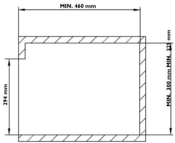
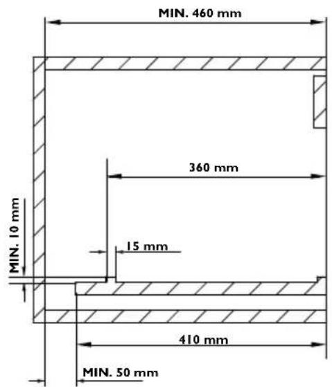
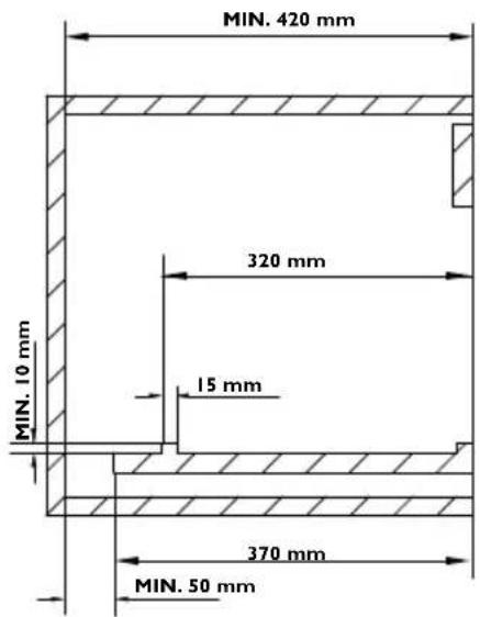
MINIMUM DISTANCES FROM WALLS TO BE RESPECTED
Always respect the minimum distances, depending on model, from walls and floor as illustrated in FIG. I - PG. 122.
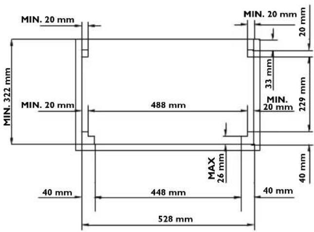
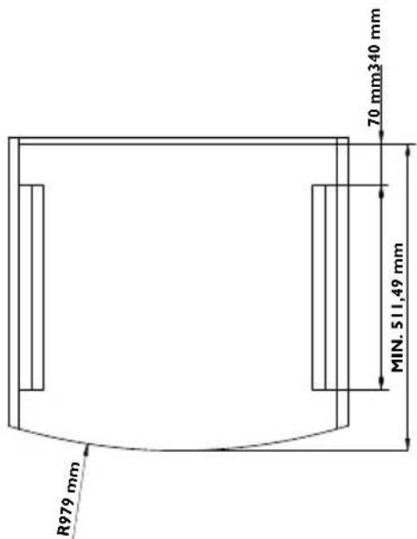
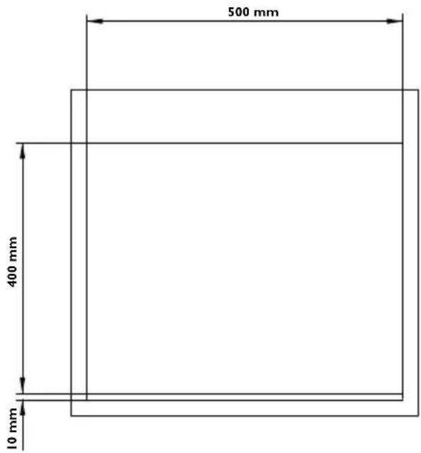
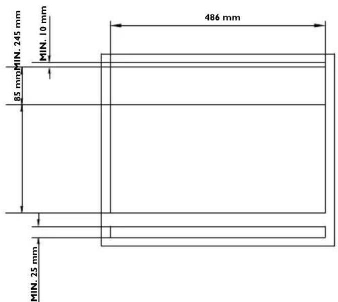
SIZE OF CABINET APERTURE
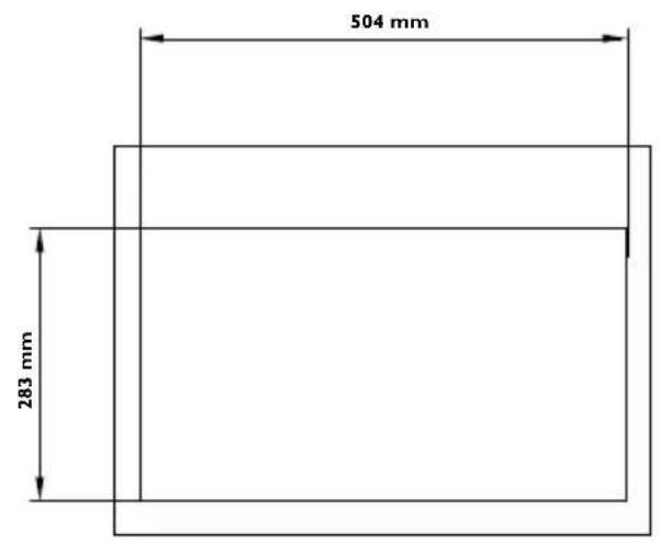
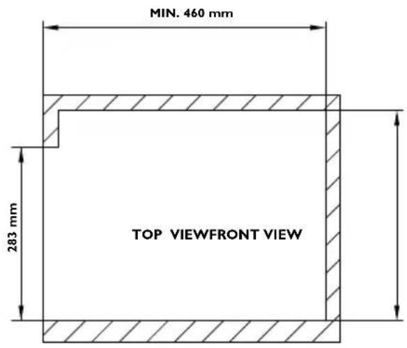
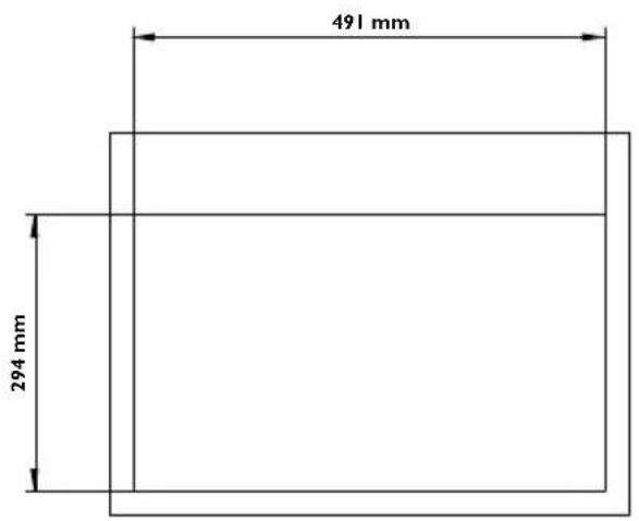
Cut-out a hole in the cabinet as illustrated in FIG. 2 - PG. 123 size will depend on appliance model.
The cabinet must be appropriately constructed and aligned horizontally with the worktop and with the unit. The cabinet aperture must be perfectly squared and aligned.
If there are apertures for cabinet ventilation, prevent flammable materials from entering.
INSTALLING THE FLUE

MODELS FO290TD - FO290TS - FO291TD - FO291TS - FO390TD - FO390TS FO391TD - FO391TS MUST BE DUCTED TO A ROOF MOUNTED FLUE.
ONLY INSTALL THE TYPE OF DUCTING AND FLUE DESCRIBED IN THESE INSTRUCTIONS WHICH CAN BE SOURCED AT SMEV OR TRUMA RETAILERS.
THE FLUE AND FUME DUCTING MUST BE POSITIONED AT A SAFE DISTANCE FROM MATERIALS WHICH ARE NOT RESISTANT TO TEMPERATURES OF 120°C.
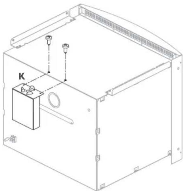
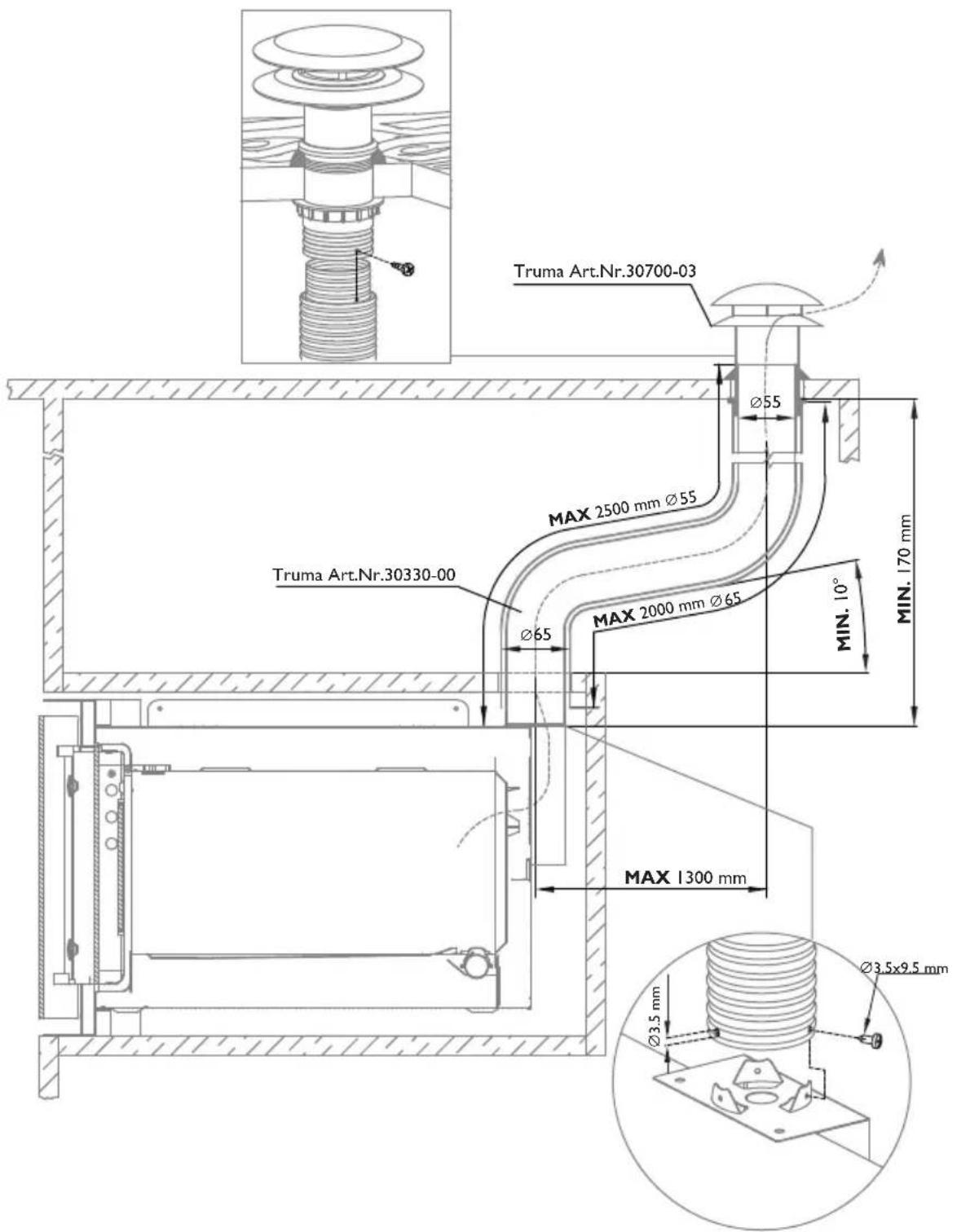
I Mount the flue attachment (K) and secure in place with the 2 fixture screws provided as illustrated in FIG. 3 - PG. 126 and then proceed with connecting the ducting to the flue.
2 The roof mounted flue must be positioned vertically with a maximum inclination of 15° . Drill a 60mm ∅ hole in the roof of the vehicle in proximity of the oven. To avoid damaging or denting the roof when installing the flue and to ensure sealing if required mount a 1mm thickness metal plate to the wall with the hole.
3 Install the flue and from the inside of the vehicle secure in place with the nut. To guarantee the roof is sealed and does not leak, after the oven has been on for several hours re-tightened the flue fixture nut.
4 Mount and install the ducting as illustrated in FIG. 4 - PG.127. Feed the ducting into the flue until it stops and secure in place with a self-tapping screw.
5 Using ties secure the ducting ( 55mm) and the protective tubing ( 65mm) for their entire lengths to the walls.
CONNECTING TO GAS SUPPLY

WARNING
CHECK THESE SPECIFICATIONS BEFORE CONNECTING THE APPLIANCE TO THE GAS CYLINDER /BOTTLE. THE PRESSURE REGULATORS CONNECTED BETWEEN THE GAS CYLINDER AND APPLIANCE MUST CONFORM WITH THE CATEGORIES GIVEN IN THE TABLE BELOW.
This appliance is designed for running off the following types of gas at the corresponding operating pressures. The gas category (or categories) of the appliance is given on the specifications label affixed to the appliance.
| CATEGORY AND COUNTRY OF DESTINATION | GAS PRESSURE |
| I3B/P(30)AT BE DE DK FI GB NL NO PT SE SI | 30 mbar Butane (G30)30 mbar Propane (G31) |
| I3+ (28-30/37)BE CH ES FR GB IE IT PT SI | 28-30 mbar Butane (G30)37 mbar Propane (G31) |
| MODEL TOTAL NOMINAL | THERMALCAPACITY | AIR VOLUME REQUIRED FOR COMBUSTION |
| FO200FT - FO200FTFEFO290TD - FO290TSFO300 - FO300LFO390TD - FO390TS | 1,2 KW - 87 gr/h | 2,4 m3/h |
| FO211FGTFO291TD - FO29ITS - FO311FO391TD - FO39ITSVN555 - VN565 | 1,6 KW - 116 gr/h | 3,2 m3/h |

WARNING
WHEN INSTALLING AND CONNECTING THE APPLIANCE TO THE GAS SUPPLY, ENSURE THAT THE GAS SUPPLY HOSE IS NOT TWISTED, STRETCHED OR SUBJECTED TO ANY FORM OF STRAIN WHICH COULD CREATE A HAZARD.
The gas supply pipe connected to the appliance must be a rigid metal pipe with sealed fittings. It is possible to fit a flexible hose, however, in this case the following conditions must be respected:
a) The hose can be accessed easily for inspection;
b) The hose must be protected against coming into contact with parts which heat up (for example parts underneath the burners);
c) The hose must be protected against being damaged (twisting, pulling, trapping,...);
d) The hose must be protected against being trapped by moving parts (e.g. drawers);
e) The hose must not have a length over 1.5 m;
f) The hose must be replaced before its expiry date;
Once the appliance has been connected to the gas supply check for gas leaks utilising a non-corrosive fluid.
Do not use a water and soap solution. NEVER USE A FLAME TO CHECK FOR GAS LEAKS.
CONNECTING TO ELECTRICITY SUPPLY
This chapter refers only to models with the wording 12 V--- on the appliance specifications label affixed to the appliance.

THIS APPLIANCE MUST BE CONNECTED TO A 12 ¥: POWER PACK ONLY. THE CIRCUIT MUST BE FITTED WITH A SAFETY FUSE NOT HIGHER THAN 3 AMP.
WHEN WIRING THE APPLIANCE RESPECT CORRECT POLARITY!

IT IS OF UTMOST IMPORTANCE NEVER TO CONNECT THIS APPLIANCE TO MAINS VOLTAGE (230 V\~) WHICH IRREVERSIBLY DAMAGES APPLIANCE COMPONENTS AND CREATES A HAZARD TO THE USER.
To connect the appliance use a 1.5 mm 2 double red and black wire and wire to the terminal junction box located at the rear of the appliance. The red terminal is the positive pole and the black terminal is the negative pole.
FIXTURE

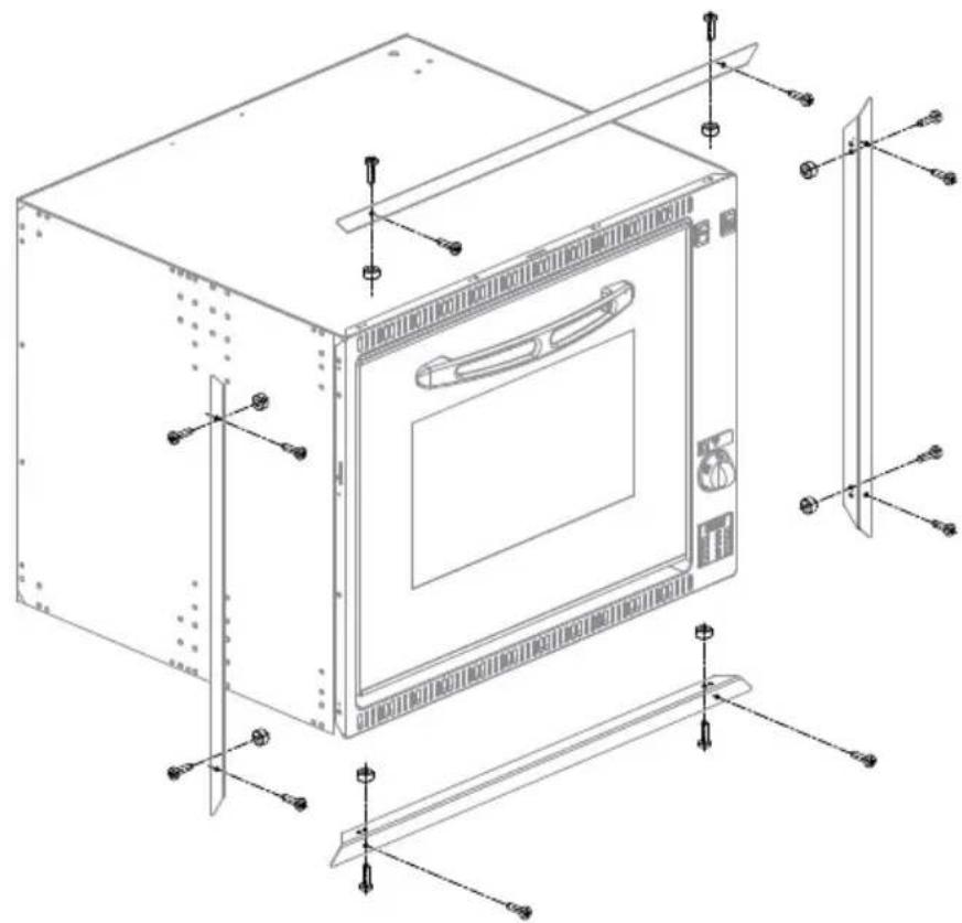
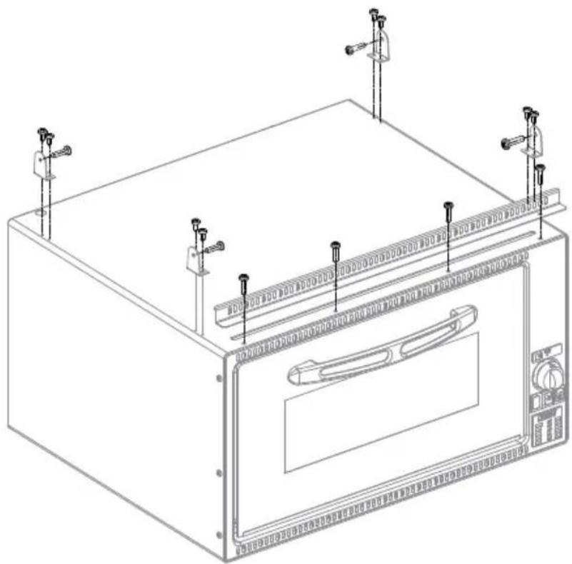
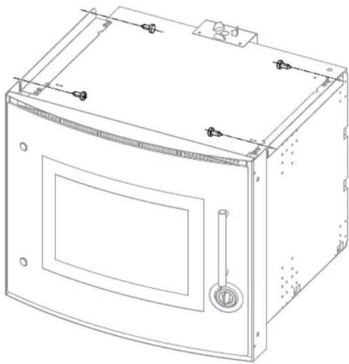
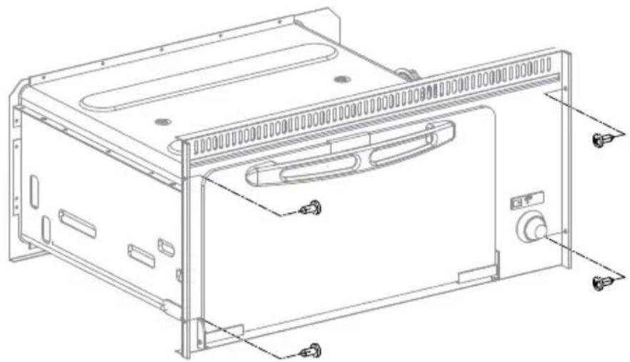
THIS APPLIANCE MUST BE FITTED AND SECURED TO THE CABINET UTILISING FIXTURE SCREWS AS ILLUSTRATED IN FIG. 5 - PG. 128.
SAFETY WARNINGS

THIS APPLIANCE MUST ONLY BE USED BY RESPONSIBLE ADULTS. DURING USE AND IMMEDIATELY AFTER USE THE BURNER AND OTHER ACCESSIBLE PARTS MAY BE HOT; DO NOT TOUCH THESE PARTS AND ALWAYS KEEP CHILDREN AT A SAFE DISTANCE. AFTER USING THE APPLIANCE ENSURE THE KNOB/KNOBS ARE OFF. AFTER USE ALWAYS SHUT OFF THE GAS SUPPLY AT THE MAIN GAS TAP.

THIS APPLIANCE MUST NOT BE USED BY PERSONS (INCLUDING CHILDREN) WHO SUFFER FROM PSYCHICAL AND MOTORY RELATED DISORDERS OR WHO ARE NOT FAMILIAR WITH OR WHO HAVE NO EXPERIENCE WITH THE APPLIANCE UNLESS UNDER SUPERVISION OR ARE BEING INSTRUCTED ON HOW TO USE THE APPLIANCE BY THE PERSON RESPONSIBLE FOR THEIR SAFETY. CHILDREN MUST ALWAYS BE SUPERVISED TO PREVENT THEM FROM PLAYING WITH THE APPLIANCE.
THE USE OF GAS APPLIANCES GENERATES HEAT AND MOISTURE IN THE IMMEDIATE AREA. ALWAYS ENSURE A GOOD VENTILATION IN THE COOKING AREA: KEEP ALL AIR VENTS OPEN FOR NATURAL VENTILATION OR INSTALL AN EXTRACTOR FAN (COOKERHOOD).
DUE TO INTENSIVE USE OF THE APPLIANCE IT MAY BE NECESSARY TO INCREASE VENTILATION SUCH AS OPENING A WINDOW OR INCREASING COOKERHOOD (EXTRACTOR FAN) SPEED.

BEFORE COOKING FOOD IN THE OVEN FOR THE FIRST TIME TURN THE OVEN ON AND LIGHT AND LEAVE ON AT MAXIMUM TEMPERATURE FOR AT LEAST 30 MINUTES. BEFORE COOKING FOOD WITH THE GRILL TURN ON AND LIGHT AND LEAVE ON FOR 15-20 MINUTES.
CONTROLS
The following symbols identify which knob corresponds to which burner. NOTE: Different models may have different knobs and different symbols.

THIS SYMBOL IS POSITIONED NEAR THE OVEN BURNER KNOB

THIS SYMBOL IS POSITIONED NEAR THE GRILL BURNER KNOB
The following symbols are for burner flame regulation and correspond to the position of the knob. NOTE: Different models may have different knobs and different symbols.

GAS OFF

HIGH FLAME

LOW FLAME
1 - 2 - 3 - 4 - 5 - 6
OVEN TEMPERATURE

GRILL
OTHER SYMBOLS

PUSHBUTTON ELECTRONIC IGNITION


THIS SYMBOL IS AFFIXED IN A CLEARLY VISIBLE POSITION NEAR THE OVEN CONTROL KNOB FOR ALL MODELS FITTED WITH ELECTRONIC IGNITION WHICH IS ACTIVATED BY MAINTAINING THE CONTROL KNOB PRESSED.

PUSHBUTTON LIGHT

SPIT FUNCTION SWITCH
SWITCH FOR ROTATING PLATE
BURNERS
Technical specifications for burners referring to appliance model:
To ignite burner, push-in and turn the control knob to a position from 1 to 6 and maintaining the knob pushed at the same time press the electronic ignition pushbutton (for models that have ★ affixed to the oven door the electronic ignition button is not visible and is activated by pressing the gas knob down). Once the burner is alight maintain the knob in this position for a few seconds to ensure the flame remains alight.

IF THE BRUNER DOES NOT IGNITE IMMEDIATELY REPEAT IGNITION AFTER HAVING FOLLOWED EACH STEP BELOW:
• PROCEED WITH MANUAL IGNITION
- CHECK THERE IS SUFFICIENT GAS IN THE GAS BOTTLE.
IF THE APPLIANCE STILL DOES NOT IGNITE SHUT OFF THE GAS SUPPLY AT THE MAIN GAS TAP AND CONTACT YOUR LOCAL DEALER.
- MANUAL IGNITION OVEN
Manual ignition when the appliance is not fitted with the electronic ignition feature or in the event of failure in the electronic ignition.
To ignite burner, gently push-in and turn the control knob to a position from 1 to 6 and maintaining the knob pushed at the same time light the burner with a match or gas lighter. Once the burner is alight maintain the knob in this position for a few seconds to ensure the flame remains alight.

IF THE BURNER DOES NOT IGNITE IMMEDIATELY CHECK THERE IS SUFFICIENT GAS IN THE GAS BOTTLE.
IF THE APPLIANCE STILL DOES NOT IGNITE SHUT OFF THE GAS SUPPLY AT THE MAIN GAS TAP AND CONTACT YOUR LOCAL DEALER.
- OVEN FLAME REGULATION WITH THERMOSTAT
| POSITIONS 1 2 3 | 4 5 6 | | | | | |
| TEMPERATURE 13 | 0° C 160° C 180° C 200° | C 220° C 240° C |
When the oven burner is ignited the flame remains at high flame in all knob positions. When the oven reaches the set temperature the flame automatically goes down to low flame.
GRILL

THE GRILL BURNER MUST BE IGNITED ONLY WITH THE DOOR FULLY OPEN.

IF THE BURNER DOES NOT IGNITE IMMEDIATELY, RELEASE THE KNOB WAIT FOR AT LEAST 10 SECONDS AND IGNITE AGAIN.
AS ACCESSIBLE PARTS MAY BE VERY HOT WHEN USING THE GRILL KEEP CHILDREN AT A SAFE DISTANCE FROM GRILL.
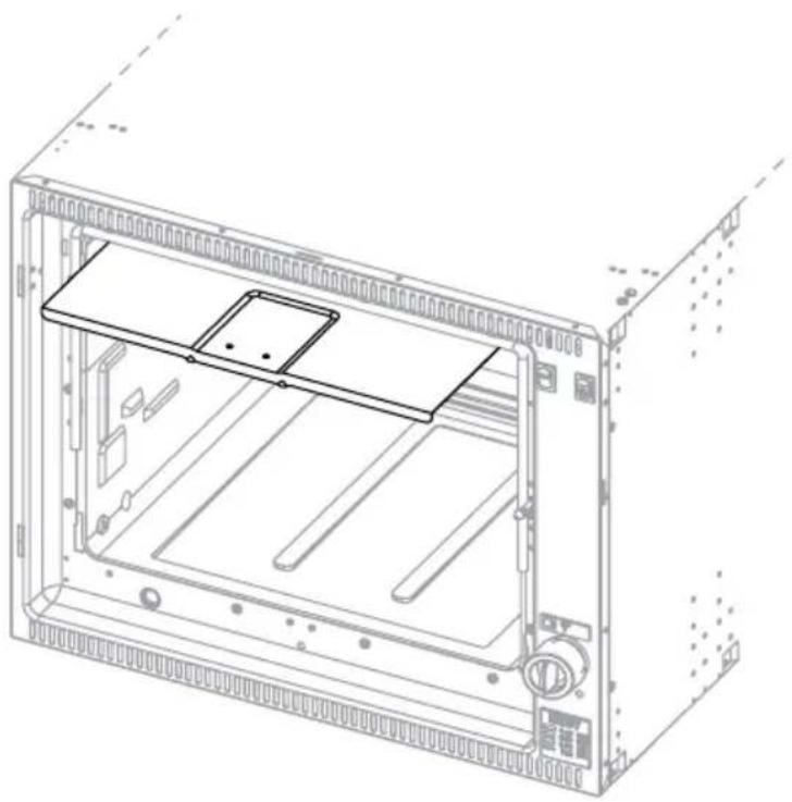
WHEN USING THE GRILL THE DOOR MUST BE KEPT OPEN AND WITH THE HEAT GUARD FULLY EXTRACTED (FIG. 6 - PG. 130).
NEVER USE THE GRILL FOR MORE THAN 25 MINUTES. THE GRILL CANNOT BE USED AS AN OVEN.
IF THE BURNER FLAME GOES OUT ACCIDENTALLY TURN OFF THE GAS KNOB AND WAIT ONE MINUTE BEFORE RE-IGNITING.
- ELECTRONIC IGNITION GRILL (DEPENDING ON MODEL)
To ignite burner, gently push-in and turn the control knob to position GRILL or HIGH FLAME and maintaining the knob pushed at the same time press the electronic ignition button (for models with the ★ symbol affixed to the door; the ignition button is not visible and is activated by pressing the knob down). Once the burner is alight maintain the knob in this position for a few seconds to ensure the flame remains alight.

IF THE BRUNER DOES NOT IGNITE IMMEDIATELY REPEAT IGNITION AFTER HAVING FOLLOWED EACH STEP BELOW:
• PROCEED WITH MANUAL IGNITION
- CHECK THERE IS SUFFICIENT GAS IN THE GAS BOTTLE.
IF THE APPLIANCE STILL DOES NOT IGNITE SHUT OFF THE GAS SUPPLY AT THE MAIN GAS TAP AND CONTACT YOUR LOCAL DEALER.
- MANUAL IGNITION GRILL
Manual ignition when the appliance is not fitted with the electronic ignition feature or in the event of failure in the electronic ignition.
To ignite burner, gently push-in and turn the control knob to position GRILL or HIGH FLAME and maintaining the knob pushed at the same time light the burner with a match or gas lighter. Once the burner is alight maintain the knob in this position for a few seconds to ensure the flame remains alight.

IF THE BURNER DOES NOT IGNITE IMMEDIATELY CHECK THERE IS SUFFICIENT GAS IN THE GAS BOTTLE.
IF THE APPLIANCE STILL DOES NOT IGNITE SHUT OFF THE GAS SUPPLY AT THE MAIN GAS TAP AND CONTACT YOUR LOCAL DEALER.
- FLAME REGULATION GRILL
For models VN555 and VN565:
to regulate flame turn the knob to the desired cooking flame.
For all other models:
the grill is to be used only at its rated thermal capacity.
VISUAL FLAME CONTROL
Depending on the type of gas used the flame should be:
Propane (G31): blue flame without yellow tips.
Butane (G30): flame with yellow tips when ignited which becomes more intense in colour as the burner heats.
SPIT
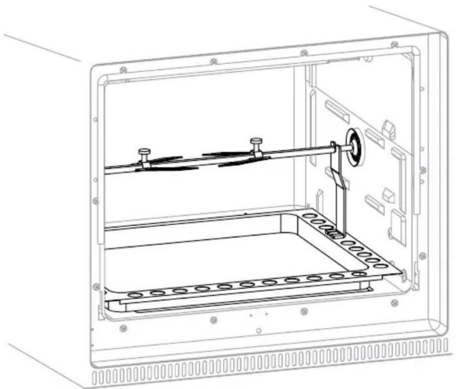
Ignite the oven as described in the chapter OVEN. Turn the gas knob to the required position. Insert the drip tray with the spit already installed as illustrated in FIG. 7 - PG. 130. Press the spit button to turn on the spit motor.
ROTATING PLATE

THE ROTATING PLATE CAN BE USED WITH THE GRILL ONLY
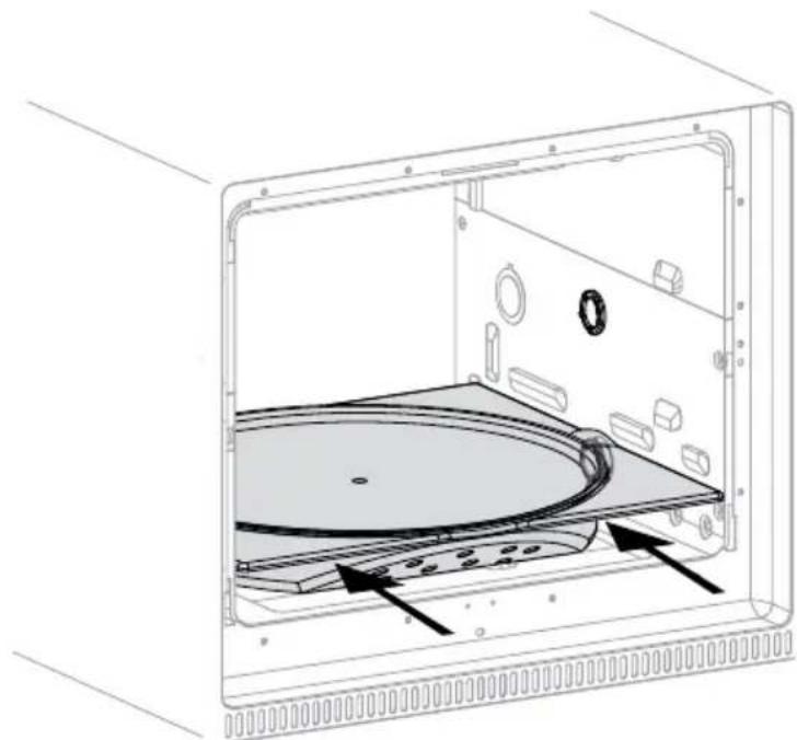
Ignite the grill burner as described in the chapter GRILL. Position the drip tray with the rotating plate as illustrated in FIG. 8 - PG. 131. Press the purpose button to turn on rotating plate motor.
NEVER OPERATE THE APPLIANCE WITH GAS AND OR AT GAS PRESSURES DIFFERENT TO THOSE INDICATED BY SMEV AS THIS COULD CAUSE IRREGULAR AND INCORRECT OPERATION. SMEV DECLINES ALL RESPONSIBILITY FOR DAMAGE OR INJURY CAUSED BY AN INCORRECT OR IMPROPER USE OF THE APPLIANCE.
The appliance runs off standard gas bottles which can be found in the country of use. The type of gas to use is clearly marked on the packaging and on the specifications label affixed to the rear of the appliance. However always respect the following instructions: gas bottles must always be located and positioned in the compartment provided for this purpose. They must always be vertical and fitted with a pressure regulator and easily accessible and not obstructed. Do not obstruct or impede access to the gas bottle to permit quick and easy access when replacing.
WARNING!: When replacing the gas bottle always take the following precautions:
a) close all gas knobs;
b) make sure there are no flames or fires in proximity of the gas bottle;
c) close the gas valve on the bottle to be replaced;
d) unscrew the pressure regulator on the empty bottle and remove the bottle from the purpose compartment. This procedure is inverted for fitting a new bottle. Check for gas leaks using a non-corrosive fluid/solution. Do not use a water and soap solution. NEVER USE A FLAME TO CHECK FOR GAS LEAKS;
e) ignite the burners to check they function correctly. If there are problems, call in an authorised gas service engineer.
AFTER APPLIANCE USE ALWAYS TURN OFF THE GAS TAP ON THE BOTTLE.
GAS LEAKS
We recommend the use of an electronic and homologated gas detector for checking for gas leaks. If there is a smell of gas;
a) immediately open the windows and evacuate the vehicle or caravan.
b) do not turn on or off light switches or other electronic and electric appliances, do not light matches or lighters or anything that could cause the gas to ignite;
c) put out any flames
d) shut off the valve on the gas bottle or cylinder. Do not re-open this valve unless the gas leak has been identified and eliminated.
e) contact a specialised gas service engineer.
CLEANING

WARNING
BEFORE CLEANING THE APPLIANCE ALWAYS TURN IT OFF AND DISCONNECT FROM POWER SUPPLY AND WAIT UNTIL IT HAS COOLED DOWN.

CAUTION
SURFACES THAT ARE STILL HOT CAN BE DAMAGED IF THEY COME INTO CONTACT WITH COLD WATER OR A DAMP CLOTH. NEVER USE ABRASIVE, CORROSIVE OR CHLORINE BASED CLEANING PRODUCTS. NEVER USE STEEL OR PLASTIC SCOURING PADS. NEVER LEAVE DEPOSITS OF ACID OR ALKALINE SUBSTANCES (VINEGAR, SALT, LEMON JUICE ETC.) ON SURFACES OF THE APPLIANCE. STAINLESS STEEL SURFACES AND ENAMELLED PARTS: CLEAN WITH A WATER AND SOAP OR NEUTRAL DETERGENT SOLUTION, RINSE AND DRY. USE CLEAN SPONGES OR CLOTHS TO CLEAN.

WARNING
NEVER USE ABRASIVE AND / OR COARSE CLEANING MATERIALS OR METAL BRUSHES TO CLEAN THE GLASS OVEN DOOR AS THESE MATERIALS SCRATCH THE GLASS SURFACE WITH THE RISK OF SHATTERING THE GLASS.
NEVER USE STEAM CLEANERS TO CLEAN THE APPLIANCE.
INJECTORS

WARNING
CLEANING OR REPLACING GAS INJECTORS MUST ONLY BE PERFORMED BY AUTHORISED AND QUALIFIED GAS SERVICE ENGINEERS. THE MANUFACTURER DECLINES ALL RESPONSIBILITY IN REGARD.
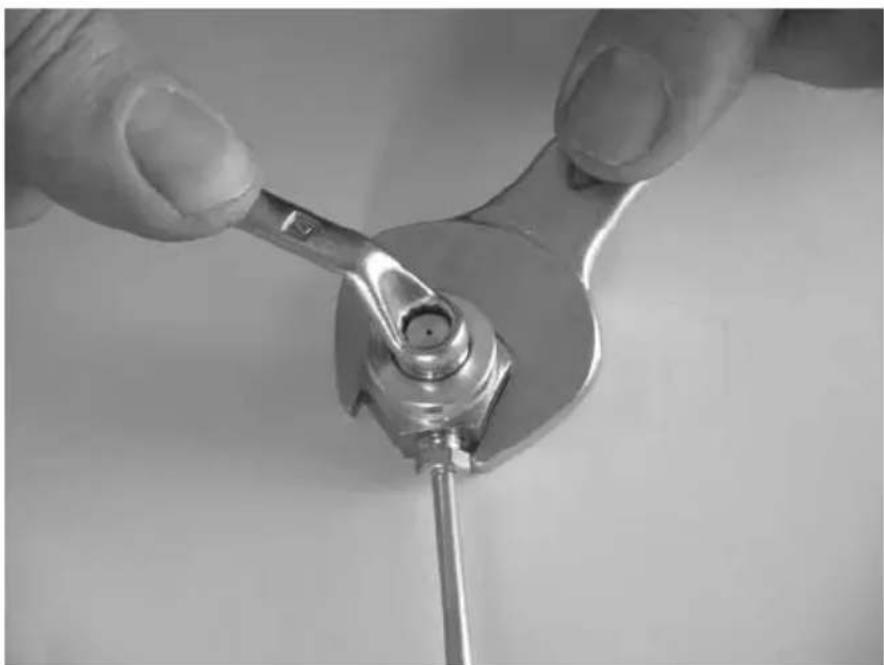
When removing and mounting the injectors the injector holder must be held in place with the aid of tool (FIG. 9 - PG. 131).
| BURNER ∅ INJECTOR (mm) | STAMPED N. |
| OVEN 0,53 53 | |
| GRILL 0,62 | 62 |
SYMBOLOGIE
ATTENTION ET SYMBOLES DE SECURITE
RACCORDEMENT AU GAZ 24
BRANCHEMENT ELECTRIQUE 25
FIXATION 25
USAGE
26
PRECAUTIONS 26
TABLEAU DE COMMANDE
BRULEURS:
FOUR:
ALLUMAGE ELECTRONIQUE DU FOUR (SELON LE MODELE) 28
ALLUMAGE MANUEL DU FOUR
REGLAGE DE LA FLAMME DU FOUR AVEC THERMOSTAT 28
GRIL:
ALLUMAGE ELECTRONIQUE DU GRIL (SELON LE MODELE) 29
ALLUMAGE MANUEL DU GRIL
REGLAGE DE LA FLAMME DU GRIL
CONTROLEVISUEL DE LA FLAMME
TOURNE-BROCHE
PLATEAUTOURNANT
BOUTEILLE DE GAZ
29
29
29
29
30
30
30
ENTRETIEN
31
NETTOYAGE
INJECTEURS
31
31
DIMENSIONS DU FOUR A ENCASTREMENT
- ALLUMAGE MANUEL DU FOUR
- ALLUMAGE MANUEL DU GRIL
WAARSCHUWINGEN EN VEILIGHEIDSSYMBOLEN
DIT APPARAAT MOET AAN HET MEUBEL WORDEN BEVESTIGD MET SCHROEVEN VOLGENS DE AFBEELDING AFB. 5 - PAG. 128.
WAARSCHUWINGEN

HET APPARAAT MAG ALLEEN DOOR VOLWASSENEN MET ZIN VOOR VERANTWOORDELIJKHEID WORDEN GEBRUIKT. TIJDENS EN ONMIDDELLIJK NA HET GEBRUIK KUNNEN BEREIKBARE DELEN HEET WORDEN; KOM ER NIET AAN EN HOUD KINDEREN UIT DE BUURT. NA HET KOKEN, ZET U ALLE KNOPPEN WEER IN HUN GESLOTEN STAND. SLUIT NA GEBRUIK OOK DE HOOFDGASKRAAN OP DE GASLEIDING.

DEZE KOOKPLAAT MAG NIET WORDEN BEDIEND OF GEBRUIKT DOOR MENSEN (INCLUSIEF KINDEREN) MET VERMINDERDE FYSIEKE, ZINTUIGLIJKE OF MENTALE CAPACITEITEN, OF DOOR MENSEN ZONDER ENIGE ERVARING OF ZONDER DE KENNIS DIE NODIG IS OM DE KOOKPLAAT TE BEDIENEN. KINDEREN MOETEN WORDEN BEWAAKT ZODAT ZE NIET MET HET APPARAAT KUNNEN SPELEN.
EEN GASKOOKTOESTEL PRODUCEERT WARMTE EN VOCHTIGHEID IN DE RUIMTE WAARIN HET WERKT. ZORG VOOR EEN GOEDE VENTILATIE IN DE KEUKEN: LAAT ALLE NATUURLIJKE VENTILATIEOPENINGEN OPEN OF INSTALLEER EEN VENTILATIESYSTEEM (ZOALS EEN AFZUIGKAP).
EEN INTENS EN LANGDURIG GEBRUIK VAN DIT APPARAAT KAN EXTRA VENTILATIE VEREISEN. IN DAT GEVAL ZET U EEN RAAM OPEN OF ZORGT U VOOR EEN BETERE MECHANISCHE VENTILATIE DOOR HET VERMOGEN VAN DE AFZUIGKAP BIJVOORBEELD TE VERHOGEN.

VOORDAT U VOOR HET EERST GERECHTEN IN DE OVEN ZET, DIENT U DE OVEN MINSTENS 30 MINUTEN OP HET MAXIMUM TE LATEN WERKEN ZONDER GERECHTEN ERIN EN DE GRILL MINSTENS 15-20 MINUTEN.
BEDIENINGSSCHERM
- MANUEL TÆNDING AF OVNEN
- MANUEL TÆNDING AF GRILLEN
INNEHÅLLSFÖRTECKNING
INSTALLATION 93
FÖRSIKTIGHETSÄTGÄRDER 93
ÖPPNING FÖR INBYGGNAD 93
ATT ANSLUTA SKORSTENEN
GASANSLUTNING 94
ELEKTRISK ANSLUTNING 95
FASTSÄTTNING 95
ANWÄNDNNG%
FÖRSIKTIGHETSÄTGÄRDER 96
KONTROLLPANEL 96
BRÄNNARE:
UGN:
ELEKTRONISK PÅSÄTTNING AV UGNEN (ENLIGT MODELL) 98
MANUELL PÄSÄTTNING AV UGNEN 98
REGLERING AV UGNENS LÄGA MED TERMOSTAT 98
GRILL: 99
ELEKTRONISK PÅSÄTTNING AV GRILLEN (ENLIGT MODELL) 99
MANUELL PÄSÄTTNING AV GRILLEN 99
REGLERING AV GRILLENS LAGA 99
VISUELL KONTROLL AV LÁGAN 99
ROTERANDE GRILLSPETT 100
ROTERANDE TALLRIK 100
GASBEHÄLLARE 100
UNDERHÅLL 101
RENGÖRING 101
INJEKTORER 101
FÖRSIKTIGHETSÅTGÄRDER

OBS! DENNA VARNINGSSKYLT ÄR PLACERAD PÅ APPARATEN. APPARATEN SKA INSTALLERAS ENLIGT GÄLLANDE BESTÄMMELSER OCH FÅR ENDAST ANVÄNDAS I EN VÄLVENTILERAD LOKAL. LÄS BRUKSANVISNINGEN INNAN APPARATEN INSTALLERAS OCH ANVÄNDS. APPARATEN SKA INSTALLERAS AV BEHÖRIGA TEKNIKER.

DENNA APPARAT FÅR ENDAST ANVÄNDAS FÖR TILLAGNING AV LIVSMEDEL. ALL ANNAN ANVÄNDNING ANSES FELAKTIG OCH ÄR DÄRFÖR FARLIG. TILLVERKAREN ANSVARAR INTE FÖR MATERIELLA SKADOR ELLER PERSONSKADOR SOM UPPSTÄR TILL FÖLJD AV EN FELAKTIG INSTALLATION ELLER FELAKTIG, SLARVIT ELLER OANSVARIG ANVÄNDNING.

INNAN INSTALLATIONEN SKA DU KONTROLLERA ATT DE LOKALA
DISTRIBUTIONSFÖRHÅLLANDENA (GASTYP OCH -TRYCK) OCH TILLSTÅNDET
FÖR APPARATENS REGLERING ÄR KOMPATIBLA.
VILLKOREN FÖR REGLERING AV DENNA APPARAT STÄR PÅ ETIKETTEN (ELLER PÅ TYPSKYLTEN).
DENNA APPARAT ÄR INTE ANSLUTEN TILL EN TÖMNINGSANORDNING FÖR FÖRBRÄNNIGNSPRODUKTER. DEN MÅSTE INSTALLERAS OCH ANSLUTAS I ENLIGHET MED DE GÄLLANDE INSTALLATIONSNORMERNA. ÄGNA SÄRSKILD UPPMÄRKSAMHET ÅT BESTÄMMELSERNA SOM GÄLLER VENTILATION.
ÖPPNING FÖR INBYGGNAD

APPARATEN SKA HÅLLAS PÅ AVSTÅND FRÅN BRANDFARLIGT MATERIAL.
Denna ugn tillhör KLASS 3: APPARAT FÖR INBYGGNAD I ETT KÖK ELLER EN KÖKSBÄNK.
MINSTA SÄKERHETSAVSTÅND TILL VÄGGAR
MANUELL TENNING AV STEKEOVNEN 108
JUSTERING AV FLAMMEN I STEKEOVNEN MED TERMOSTAT 108
GRILL:
ELEKTRONISK TENNING AV GRILLEN (AVHENGIG AV MODELLEN) 109
MANUELL TENNING AV GRILLEN
JUSTERING AV FLAMMEN I GRILLEN 109
VISUELL KÖNTROLL AV FLAMMEN
GRILLSPYD
ROTERENDE TALLERKEN
GASSFLASKE
106
107
108
108
108
108
109
109
109
109
109
110
110
110
VEDLIKEHOLD
III
RENGJ∅RING
INNSPR∅YTERE
III
111
|22-13|
FORHOLDSREGLER

ADVARSEL: DENNE ADVARSELEN ER PLASSERT PÅ APPARATET. APPARATET MÅ INSTALLERES I HENHOLD TIL GJELDENDE LOVER. APPARATET SKAL BARE BRUKES PÅ ET STED MED EGNET VENTILASJON. LES INSTRUKSJONENE F∅R DU INSTALLERER OG BRUKER APPARATET. APPARATET MÅ INSTALLERES AV AUTORISERT PERSONALE.
APPARATET SKAL BARE BRUKES TIL MATLAGING. HVILKEN SOM HELST ANNEN BRUK ER Å REGNE SOM FEIL OG DERMED FARLIG BRUK. PRODUSENTEN ER IKKE ANSVARLIG FOR SKADER PÅ PERSONER ELLER GJENSTANDER SOM F∅LGE AV FEIL INSTALLASJON, UEGNET BRUK, FEIL ELLER UANSVARLIG BRUK.

F∅R INSTALLASJONEN, KONTROLLER AT DE LOKALE VILKÅRENE FOR FORSYNING (GASSENS NATUR OG TRYKK) OG APPARATETS JUSTERING ER KOMPATIBLE.
APPARATETS JUSTERINGSVILKÄR ER OPPGITT PÅ ETIKETTEN (ELLER PÅ MERKESKILTET).
APPARATET ER IKKE KOPLET TIL EN UTSUGINGSANORDNING FOR FORBRENNINGSPRODUKTENE. UTSUGINGSANORDNINGEN MÅ INSTALLERES OG TILKOPLES I SAMSVAR MED GJELDENDE INSTALLASJONSBESTEMMELSER. VÆR SPESIELT OPPMERKSOM PÅ GJELDENDE VENTILASJONSKRAV.
FORSENKNINGSHULL
APPARATET MÅ STÅ VEKKE FRA BRENNBARE MATERIALER.
Denne stekeovnen tilhører KLASSE 3: APPARAT SOM SKAL INNEBYGGES I ET KJ∅KKENSKAP ELLER I EN ARBEIDSBENK.
MIN. AVSTANDER FRA VEGGENE
INNEBYGGINGSHULLETS MÅL
- MANUELL TENNING AV STEKEOVNEN
- MANUELL TENNING AV GRILLEN
2 FIG
FO200FT
FO2IIFGT
FRONT VIEW SIDE VIEW
FO200FTFE
FRONT VIEW SIDE VIEW
FO290TD
FO290TS
FO291TD
FO291TS
FRONT VIEW TOP VIEW
FO300
FO300L
FO311
FRONT VIEW SIDE VIEW
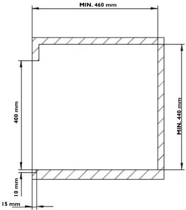
FO390TD
FO390TS
FO391TD
FO391TS
FRONT VIEW TOP VIEW
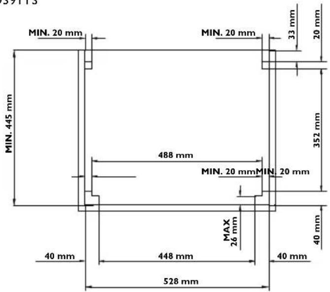
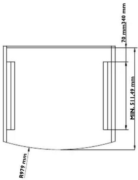
VN555 FRONT VIEW SIDE VIEW
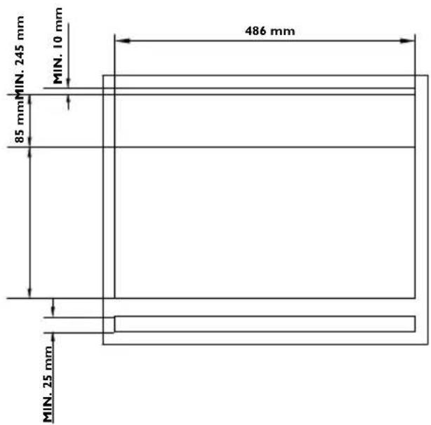
VN565 FRONT VIEW SIDE VIEW
3 FIG.
4 FIG
5 FIG
FO200FT
FO21IFGT
FO300
FO300L
FO311
F0200FTFE
FO290TD
FO290TS
FO291TD
FO291TS
FO390TD
FO390TS
FO391TD
FO391TS
VN555
VN565
6 FIG.
7 FIG.

FIG

FIG