
FMJ AVR360 - Receiver ARCAM - Free user manual and instructions
Find the device manual for free FMJ AVR360 ARCAM in PDF.

| Product type | Home theater receiver |
| Brand | Arcam |
| Model | FMJ AVR360 |
| Dimensions (W x D x H) | 433 x 425 x 171 mm |
| Net weight | 15.5 kg |
| Packaged weight | 20 kg |
| Supply voltage | 220-240 V, 50 Hz |
| Maximum power consumption | 1 kW |
| Standby power consumption | < 0.5 W |
| Output power (2 channels, 8 Ω, 20 Hz-20 kHz, <0.02% THD) | 80 W per channel |
| Output power (5 channels, 8 Ω, 1 kHz, 0.2% THD) | 75 W per channel |
| Audio inputs | 7 analog, 6 digital (coaxial, optical), MCH, USB, network |
| Video inputs | HDMI (x4), Component, S-Video, Composite, RGB |
| Outputs | HDMI with ARC, 7.1 preamp, subwoofer, Zone 2, headphone |
| Supported audio formats | Dolby TrueHD, DTS-HD Master Audio, Dolby Digital Plus, AAC, FLAC, MP3, WMA |
| Tuner | AM, FM, DAB (depending on region) |
| Connectivity | Ethernet, RS232, IR, 12V triggers |
| Remote control | CR102 universal with learning and macro |
| Supplied accessories | Power cable, CR102 remote control, 4 AAA batteries, DAB/FM/AM antennas, calibration microphone |
| Cleaning | Dry lint-free cloth; do not use chemical cleaners |
| Safety | Double insulation (Class II), do not obstruct ventilation, leave >0.3 m of space |
| Repair instructions | Refer to qualified technician; do not open the enclosure |
Frequently Asked Questions - FMJ AVR360 ARCAM
User questions about FMJ AVR360 ARCAM
0 question about this device. Answer the ones you know or ask your own.
Ask a new question about this device
Download the instructions for your Receiver in PDF format for free! Find your manual FMJ AVR360 - ARCAM and take your electronic device back in hand. On this page are published all the documents necessary for the use of your device. FMJ AVR360 by ARCAM.
USER MANUAL FMJ AVR360 ARCAM
HANDBOOK AVR surround amplifier


CAUTION
RISK OF ELECTRIC SHOCK/SHOCK DISEASE
ATTENTION
RISQUE DE CHOC ELECTRONIQUE R.245-1086

CAUTION. To reduce the risk of electric shock, do not remove cover (or back). No user serviceable parts inside. Refer servicing to qualified service personnel.
WARNING: To reduce the risk of fire or electric shock, do not expose this apparatus to rain or moisture.
The lightning flash with an arrowhead symbol, within an equilateral triangle, is intended to alert the user to the presence of uninsulated dangerous voltage within the products enclosure that may be of insufficient magnitude to constitute a risk of electric shock to persons.
The explanations point within an equilateral triangle is intended to alert the user to the presence of important operating and maintenance (servicing) instructions in the literature accompanying the appliance.
CAUTION In Canada and the USA, to prevent electric shock, match the wide blade of the plug to the wide slot in the socket and insert the plug fully into the socket.
Important safety instructions
- Read these instructions.
- Keep these instructions.
- Heed all warnings
- Follow all instructions.
- Do not use this apparatus near water.
- Clean only with a dry cloth.
Unplug the unit from the mains supply before cleaning. The case should normally only require a wipe with a soft, lint-free cloth. Do not use chemical solvents for cleaning. We do not advise the use of furniture cleaning sprays or polishes as they can cause permanent white marks.
7. Do not block any of the ventilation openings. Install in accordance with the manufacturer's instructions.
8. Do not install near any heat sources such as radiators, heat registers, stoves, or other apparatus (including amplifiers) that produce heat.
9. Do not defeat the safety purpose of the polarized or grounding type plug.
A polarized plug has two blades with one wider than the other. A grounding type plug has two blades and a third grounding prong. The wide blade or the third prong is provided for your safety. When the provided plug does not fit into your outlet, consult an electrician for replacement of the obsolete outlet.
- Protect the power cord from being walked on or pinched particularly at plugs, convenience
receptacles, and the point where they exit from the apparatus.
-
Only use the attachments/accessories specified by the manufacturer.
-
Use only with a cart, stand, tripod, bracket, or table specified by the manufacturer, or sold with the apparatus.

When a cart is used, use caution when moving the cart/apparatus combination to avoid injury from tip-over.
13. Unplig this apparatus during lightning storms or when unused for long periods of time.
-
Refer all servicing to qualified service personnel. Servicing is required when the apparatus has been damaged in any way, such as power supply cord or plug is damaged, liquid has been spilled or objects have fallen into the apparatus, the apparatus has been exposed to rain or moisture, does not operate normally, or has been dropped.
-
Object or liquid entry
WARNING - Take care that objects do not fall and liquids are not spilled into the enclosure through any openings. The equipment shall not be exposed to dripping or splashing. Liquid-filled objects such as vases should not be placed on the equipment.
- Service Instructions
CAUTION - These servicing instructions are for use by qualified service personnel only. To reduce the risk of
electric shock, do not perform any servicing other than that contained in the operating instructions unless you are qualified to do so.
- Climate
The equipment has been designed for use in moderate climates and in domestic situations. Unplug this equipment during lightning storms to prevent possible damage from a strike or mains surge.
- Power sources
Only connect the equipment to a power supply of the type described in the operating instructions or as marked on the equipment.
The primary method of isolating the equipment from the mains supply is to remove the mains plug. The equipment must be installed in a manner that makes disconnection possible.
- Power-cord protection
Power supply cords should be routed so that they are not likely to be walked on or pinched by items placed upon or against them. Pay particular attention to the point where they exit from the equipment.
- Power lines
Locate any outdoor antenna/acroial away from power lines.
- Speaker connections
Any speakers must be connected to the AVR360 using class II wire (i.e. no connection to Parth should be made). Failure to observe this precaution may cause the unit to become damaged.
- Non-use periods
If the equipment is not being used for an extended period, we recommend that you unplug the power cord of the equipment from the outlet, to save power.
- Abnormal smell
If an abnormal smell or smoke is detected from the equipment, turn the power off immediately and unplug the equipment from the wall outlet. Contact your dealer and do not reconnect the equipment.
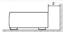
For proper heat dispersal, do not install this unit in a confined space, such as a bookcase or similar enclosure.
More than 0.3 m (12 in.) is recommended.
Do not place any other equipment on this unit.
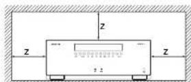
CAUTIONS ON INSTALLATION
FCC inFoRmation (FoR us CustomcRs)
1.PRoDuCt
This product complies with Part 15 of the FCC Rules. Operation is subject to the following two conditions: (1) This device may not cause harmful interference, and (2) this device must accept any interference received, including interference that may cause undesired operation.
2.imPoRrant notice:
Do not moDiFy His PRoDuCt
This product, when installed as indicated in the instructions contained in this manual, meets FCC requirements. Modification not expressly approved by ARCAM may void your authority; granted by the FCC, to use the product.
3. note
This product has been tested and found to comply with the limits for a Class B digital device, pursuant to Part 15 of the I-CC Rules. These limits are designed to provide reasonable protection against harmful interference in a residential installation.
This product generates, uses and can radiate radio frequency energy and, if not installed and used in accordance with the instructions, may cause harmful interference to radio communications. However, there is no guarantee that interference will not occur in a particular installation. If this product does cause harmful interference to radio or television reception, which can be determined by turning the product OFF and ON, the user is encouraged to try to correct the interference by one or more of the following measures:
Reorient or relocate the receiving antenna.
- Increase the separation between the equipment and receiver.
- Connect the product into an outlet on a circuit different from that to which the receiver is connected.
- Consult the local retailer authorized to distribute this type of product or an experienced radio/TV technician for help.
saFety inFoRmation
(FoReeuRoPean Cus tomeRs)
- Avoid high temperatures. Allow for sufficient heat dispersion when installed in a rack.
- Handle the power cord carefully. Hold the plug when unphugging the cord.
- Keep the unit free from moisture, water, and dust.
- Unplug the power cord when not using the unit for long periods of time.
- Do not obstruct the ventilation holes.
- Do not let foreign objects into the unit.
- Do not let insecticides, benzene, and thinner come in contact with the unit.
- Never disassemble or modify the unit in any way.
-
Ventilation should not be impeded by covering the ventilation openings with items, such as newspapers, tablecloths or curtains.
-
Naked flame sources such as lighted candles should not be placed on the unit.
- Observe and follow local regulations regarding battery disposal.
- Do not expose the unit to dripping or splashing fluids.
-
Do not place objects filled with liquids, such as vases, on the unit.
Do not handle the mains cord with wet hands. -
When the switch is in the OFF position, the equipment is not completely switched off from MAINS.
The equipment shall be installed near the power supply so that the power supply is easily accessible.
a note aBout ReCyClinG:
This product's packaging materials are recyclable and can be reused. Please dispose of any materials in accordance with the local recycling regulations.When discarding the unit, comply with local rules or regulations.
Batteries should never be thrown away or incinerated but disposed of in accordance with the local regulations concerning battery disposal.
This product and the supplied accessories, excluding the batteries, constitute the applicable product according to the WEEF directive.
CoRRcT DisPosal of tllis PRODuCt
These markings indicate that this product should not be disposed with other household waste throughout the EU. To prevent possible harm to the environment or human health from uncontrolled waste disposal and to conserve material resources, this product should be recycled responsibly.

m = 311

13/14

Pb
To dispose of your product, please use your local return and collection systems or contact the retailer where the product was purchased.
Contents
Safety E-2
Welcome E-5
Before you begin E-6
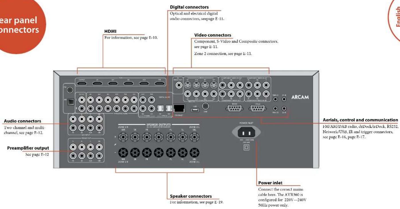
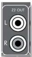
Rear Panel Connectors E-9
Audio/Video Connections E-10
Connection Guide E-14
Radio Connectors E-16
Other Connectors E-17
Speakers E-18
Operation E-20
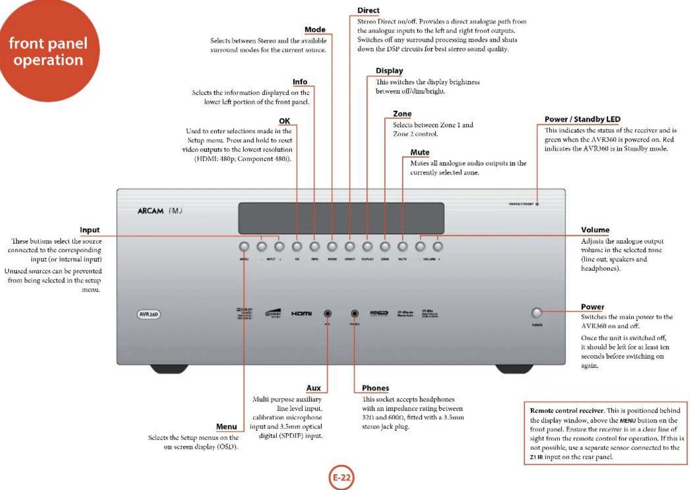
Front Panel Operation E-22
Remote Control E-23
Essential Setup E-32
Auto Speaker Setup. E-33
Setup Menus E-34
Decoding Modes E-40
Dolby Volume E-42
Tuner Operation E-44
Network/USB Operation.. E-45
Multi-Room Set Up E-46
Multi-Room Connection Guide E-47
Customising the CR102 E-48
Command Summary E-51
Device Codes E-51
Trouble shooting. E-52
Specifications.. E-54
Product Guarantee E-55
Device Code Tables 56
Thank you and congratulations on purchasing your Arcam FMJ AVR360 Receiver.
Arcam has been producing specialist audio products of remarkable quality for over three decades and the new AVR360 Receiver is the latest in a long line of award winning Hi-Fi. The design of the FMJ range draws upon all of Arcam's experience as one of the UK's most respected audio companies, to produce Arcam's best performing range of products yet - designed and built to give you years of viewing and listening enjoyment.
This handbook is intended to give you a detailed guide to using the AVR360 Receiver. It starts by giving advice on installation, moves on to describe how to use the product and finishes with additional information on the more advanced features. Use the contents list shown on this page to guide you to the section of interest.
We hope that your FMJ receiver will give you years of trouble-free operation. In the unlikely event of any fault, or if you simply require further information about Arcam products, our network of dealers will be happy to help you. Further information can also be found on the Arcam website at www.arcam.co.uk.
The FMJ development team
Professional Installation?
It may be that the AVR360 has been installed and set up as part of your Hi-Fi installation by a qualified Arcam dealer. In this case, you may wish to skip the sections of this handbook dealing with installation and setting up, and move directly to the sections dealing with using the unit. Use the Contents list to guide you to these sections.
DIY setup?
The AVR360 is a powerful and sophisticated piece of AV equipment. If you are setting the unit up yourself, it is recommended that you read this handbook thoroughly before beginning. For instance, correct speaker configuration and placement is a key to getting the most out of your AVR360 and making sure that all the elements of your system work in harmony.


The AVR360 is a high-quality and high-performance home cinema processor and amplifier built to Arcan's quality design and manufacturing standards. It combines digital processing with high-performance audio and video components to bring you an unrivalled home-entertainment centre.
The AVR360 allows switching and control of seven analogue and six digital audio sources in addition to internal AM, FM and DAB radio - as well as networked and USB audio sources - making it an ideal hub for both home-cinema and two-channel stereo systems.
Since many of these source components are also capable of generating video signals, the AVR360 includes broadcast-quality switching for HDMI, Composite, S-Video, RGB and Component video signals. BD-Audio and SACD can be connected via the multi channel
input. Control of the AVR360 is either by front panel control buttons, IR remote control or RS232 port.
The CR102 remote control supplied with the AVR360 is an eight device 'universal' learning remote control which is simple to use, and once set up is able to control a complete system. It can be programmed using its vast internal code library to control CD and BD players, PVRs, TVs and other devices.
The installation of the AVR360 in a listening room is an important process which requires care at every stage. For this reason, the installation information is very comprehensive and should be followed carefully to achieve an unrivalled level of performance.
The AVR360 receiver is designed to produce a level of performance that will truly bring music and movies to life.
Placing the unit
Place the unit on a level, firm surface, avoiding direct sunlight and sources of heat or damp.
Do not place the AVR360 on top of a power amplifier or other source of heat.
Do not place the amplifier in an enclosed space such as a bookcase or closed cabinet unless there is good provision for ventilation. The AVR360 will run warm during normal operation.
Do not place any other component or item on top of the amplifier as this may obstruct airflow around the heat-sink, causing the amplifier to run hot. (The unit placed on top of the amplifier would become hot, too.)
Make sure the remote-control receiver on the front panel display is unobstructed, otherwise this will impair the use of the remote-control. If line-of-sight is impractical, a remote-control repeater can be used with the rear panel connector (see page E-17).
- Do not place your record deck on top of this unit. Record decks are very sensitive to the noise generated by mains power supplies which will be heard as a background 'hum' if the record deck is too close.
Power
The amplifier is supplied with a moulded mains plug already fitted to the lead. Check that the plug supplied fits your supply - should you require a new mains lead, please contact your Arcam dealer.
The AVR360 is designed for a mains supply voltage of 220 - 240V nominal voltage 230V . If your mains supply voltage or mains plug is different, please contact your Arcam dealer immediately.
Push the IFC plug end of the power cable into the socket on the back of the amplifier, making sure that it is pushed in firmly. Plug the other end of the cable into your mains socket and, if necessary, switch the socket on.
The AVR360 can be turned on using the POWER switch on the front panel. While switched on, the front panel LED will glow green.
Standby power
The AVR360 can be switched into standby mode using the button on the CR102 remote control. While in standby mode the front panel Le1 will glow red and power consumption is less than 0.5 Watts.
While in Standby mode, it may be possible to hear a slight residual hum coming from the mains transformer inside the amplifier. This is perfectly normal. However, if the unit is to be left unused for an extended period, we recommend that you disconnect it from the mains supply to save power.
Interconnect cables
We recommend the use of high-quality screened cables that are designed for the particular application. Other cables will have different impedance characteristics that will degrade the performance of your system (for example, do not use cabling intended for video use to
carry audio signals). All cables should be kept as short as is practically possible.
It is good practice when connecting your equipment to make sure that the mains power-supply cabling is kept as far away as possible from your audio cables. Failure to do so may result in unwanted noise in the audio signals. For information on speaker cabling, please refer to the 'Speakers' section, beginning on page E-18.
Radio interference
The AVR360 is an audio device containing microprocessors and other digital electronics. It has been designed to very high standards of electromagnetic compatibility.
This is a Class A product. In a domestic environment this product may cause radio interference, in which case the user may be required to take adequate measures.
If the AVR360 causes interference to radio or television reception (which can be determined by switching the AVR360 off and on), the following measures should be taken:
Re-orient the receiving antenna or route the antenna cable of the affected receiver as far as possible from AVR360 and its cabling.
Relocate the receiver with respect to the AVR360. Connect the affected device and the AVR360 to different mains outlets.
If the problem persists, please contact your Arcam dealer.
Trademark acknowledgements
Arcam is a registered trademark of A & R Cambridge Ltd.
| DOLBY VOLUME | Dolby Volume Manufactured under license from Dolby Laboratories. Dolby and the double-D symbol are trademarks of Dolby Laboratories. |
| DOLBY TRANSMITTER Digital Plus PRO LOGIC B1 | Dolby TrueHD, Digital, Digital Plus, PL IIx Manufactured under license from Dolby Laboratories. Dolby, Pro Logic, and the double-D symbol are trademarks of Dolby Laboratories. |
| dts-no Master Audio | DTS-HD Master Audio Manufactured under license under U.S. Patent: Nov 5,956,674, 5,974,380, 6,226,616, 6,487,535, 7,212,872, 7,333,929, 7,392,195, 7,272,567 & other U.S. and worldwide patents issued & pending. DTS-HD, this Symbol, & DTS-HD and the Symbol together are registered trademarks & DTS IID Master Audio is a trademark of DTS, Inc. Product includes software. & DTS, Inc. All Rights Reserved. |
| DTS-HD High Resolution Audio Manufactured under license under U.S. Patent: Nov 5,956,674, 5,974,380, 6,226,616, 6,487,535, 7,212,872, 7,333,929 & other U.S. and worldwide patents issued & pending. DTS IID, the Symbol, & DTS-HD and the Symbol together are registered trademarks & DTS-HD High Resolution Audio is a trademark of DTS, Inc. Product includes software. & DTS, Inc. All Rights Reserved. | |
| dts Digital Surround ES | No6 | No74 | DTS Digital Surround ES|Neo:6|96/24 Manufactured under license under U.S. Patent: Nov 5,956,674, 5,974,380, 6,226,616, 6,487,535, 7,002,467, 7,212,872 & other U.S. and worldwide patents issued & pending. DTS, this Symbol, & DTS and the Symbol together are registered trademarks & DTS Digital Surround | ES | Neo6 | No74 is a trademark of DTS, Inc. Product includes software. & DTS, Inc. All Rights Reserved. |
| AAC/AAC Plus aacPlus is a trademark of Coding Technologies. See www.codingtechnologies.com for more information. | |
| FLAC | FLAC Decoder Copyright © 2000, 2001, 2002, 2003, 2001, 2005, 2006, 2007, 2008 Joshi condusion ReDistribution and use in source and binary forms, with or without modification, are permitted provided that the following conditions are met: - Redistributions of source code must receive the above copyright notice, this list of conditions and the following disclaimer: - Redistributions in binary form must rep dicate the above copyright notice, this list of conditions and the following disclanlars in the documentation and/or other materials provided with the distribution. - Neither the name of the Xiphory Foundation nor the names of its contributors may be used to endow, or promote, products derived from this software without specific prior written permission. THIS SOFTWARE IS PROVIDED BY THE COPYRIGHTS HOLDERS AND CONTRIBUTORS "AS IS" AND ANY EXPRESS OR IMPLIED WARRANTY, INCLUDING, BUT NOT LIMITED TO, THE IMPLIED WARRANTIES OF MERCHANT LIABILITY AND FITNESS FOR A PARTICULAR PURPOSE ARF DISCLAIMED IN NO EVENT SHALL THE FOUNDATION OR CONTRIBUTORS BE LIABLE FOR ANY DIRECT, INDIRECT, INCIDENTAL, SPECIAL, EXPIRATORY, OR CONSEQUENTIAL DAMAGES INCLUDING, BUT NOT LIMITED TO, PROCUREMENT OF SUBSTITUTE GOODS OR SERVICES; LOSS OF USE, DATA, OR PROFITS OR BUSINESS INTERRUPTING (HOWEVER CAUSED AND ON ANY THEORY OF LIABILITY, WHETHER IN CONTRACT, STRICT LIABILITY, OR PORT (INCLUDING NEIGHANCE OR OTHERWISE) ASING IN ANY WAY OUT OF THE USE OF THIS SOFTWARE, EVEN IF ADJISSED OF THE POTIBILITY OF SUCH DAMAGE. |
| vTuner | This product is protected by certain intellectual property rights of VEMS and BridgeCo. Use or distribution of such technology outside of this product is prohibited, without a license from VEMS and BridgeCo or an authorized subsidiary. |
| MP3 | MPEG Layer-3 audio decoding technology licensed from Fraunhofer IIS and Thomson multimedia. |
| iPod | iPod is a trademark of Apple Inc., registered in the US and other countries. |
| HOMI | HDMI, the HDMI logo and High-Definition Multimedia Interface, are trademarks or registered trademarks of HDMI Licensing LLC. |
| ROVI | This item incorporates copy protection technology that is protected by U.S. patents and other collective property rights of Rovi Corporation. Reverse engineering and disassembly are prohibited. |

NOTE
Please read the 'Placing the unit', 'Power' and 'Interconnect cables' sections on page F-7 before connecting up your AVR360 integrated amplifier!

Before connecting your AVR360 to your source components and speakers, please read through the next few pages which will explain all the input and output connectivity that is available. The 'Speakers' section explains how to connect up your speakers to avoid damage to the amplifier and how to arrange your speakers for best performance.
General
The inputs are named to make it easier to reference connected devices (e.g. BD or VCR). They all have the same input circuit, so there is no reason why you should not connect a different device to any of the inputs. For example, if you had two BD players and the AV input was not being used, then the second BD player could be connected to the AV input.
When connecting a video source, its audio must be connected to the corresponding sockets. For example, if you had a satellite decoder plugged into a SAT video input, the audio must be connected to the SAT audio inputs!
The hierarchy for video connections for best quality is as follows:
HDM1
Component/RG8
S-Yidco
Composite.
For any video source to be available in Zone 2 you must have a Composite connection between AVR360 and the source.
Making connections
- Wherever possible, connect both the analogue and digital outputs of digital sources. This enables use of a digital input for the main zone and the corresponding analogue input for the Zone 2 output.
- Take care to place cables as far from any power supply cabling as is practicable, to reduce hum and other noise problems.
NOTE:
For each input, you must set the "Video Source" and "Audio Source" settings according to the connection type. (see "Input Config." on page E-35)
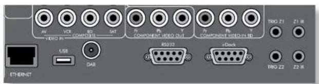
HDMI connectors
AV, SAT, BD, VCR, PVR
Connect the HDMI video outputs of your source equipment to these corresponding HDMI inputs.
OUTPUT
Connect this output to the HDMI video input of your display device. This output is compatible with the HDMI L4 Audio Return Channel (ARC). If you have a supported television then sound from the television's internal tuner (e.g., Freeview, Freesat, DVB-T) will be available using the AVR360's "Display" input.
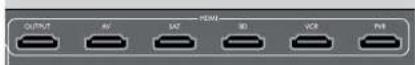
Component/RGB video connectors
These inputs are suitable for connection to source devices which output Component (YUV or YPbPr) or RGB high quality analogue video signals. These signals are usually available from BD players, set-top boxes or games consoles.
If you are connecting up to an RGB source you may also need to connect the source's Composite output to the AVR360 Composite input to act as a video sync ('RGB +Sync' formal). The Composite signal should be on the same named input as the RGB signals. The AVR360 is also compatible with 'Sync on Green' or 'RGB' signals. RGB video outputs on source equipment are often on SCART connectors. You will need to use a SCART to 'RGB+Sync on phono' breakout cable, available from your Arcam dealer.
NOTE
When setting up the AVR360 menus (later in this manual), you will need to select whether the three wire high quality video input is Component ('Normal'), 'RGB' or RGB Sync for each input. This is done on the Component Mode line in the Input Config menu. Failure to do this can result in a green looking picture or a picture that is unstable.
COMPONENTVIDEO IN SAT,AV,BD
Connect the Component video outputs of your source equipment to these inputs.
COMPONENTVIDEOOUT
Connect this output to the Component video input of your display device.
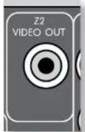
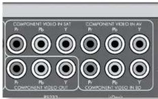
Zone 2 connectors
The 22 out analogue audio connector can be used to connect the stereo audio output of the AVR360 to an amplifier located in a second room. Connect the analogue video output to your Zone 2 display equipment. See 'Multi-room Setup' on E-46 for information.
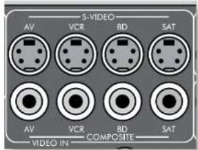
S-Video and Composite connectors
AV, VCR, BD, SAT
Connect these inputs to the S-Video and Composite outputs of your available source equipment.
Digital audio connectors
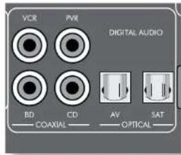
VCR, PVR, BD, CD, AV, SAT
Connect these inputs to the digital outputs of your available source equipment.
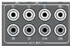
MCH input
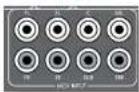
This multi-channel analogue audio input can be connected to a source device which outputs surround sound on its analogue outputs. Such devices typically include DVD-Audio
and SACD players. This input does not pass through any of the audio processing in the AVR360, therefore functions such as speaker size and distance from the listening position should be copied from the AVR360 Setup menus into the Setup menus of your multi-channel source.Note however that speaker level trims are applied to the MCH input on the AVR360.Therefore speaker level trim settings on multichannel source equipment should be left unset at zero.
Analogue pre-amplifier outputs
All pre-amplifier analogue outputs are buffered, have a low output impedance, are at line level and follow the Zone 1 volume control setting. They are able to drive
long cables or several inputs in parallel if required. For more information on connecting speakers or additional power amplifiers, see page F-18 and F-19.
Analogue audio inputs
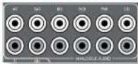
AV, SAT, BD, VCR, PVR, CD
Connect the left and right inputs to the left and right outputs of your source equipment.
Front panel AUX input
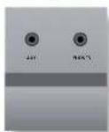
The front panel AUX input can be used as an analogue or optical digital input.
For analogue sources, use a stereo 3.5mm lead; for digital sources use a 3.5mm optical lead. The front input is also used for the auto-setup microphone input.
Front panel PHONES socket
This socket accepts headphones with an impedance rating between 32Ω and 600Ω, fitted with a 3.5mm stereo jack plug. The headphone socket is always active, except when AVR360 is muted.
When the headphone jack is inserted, the speaker outputs and analogue pre-amplifier outputs are automatically muted.

Connection guide
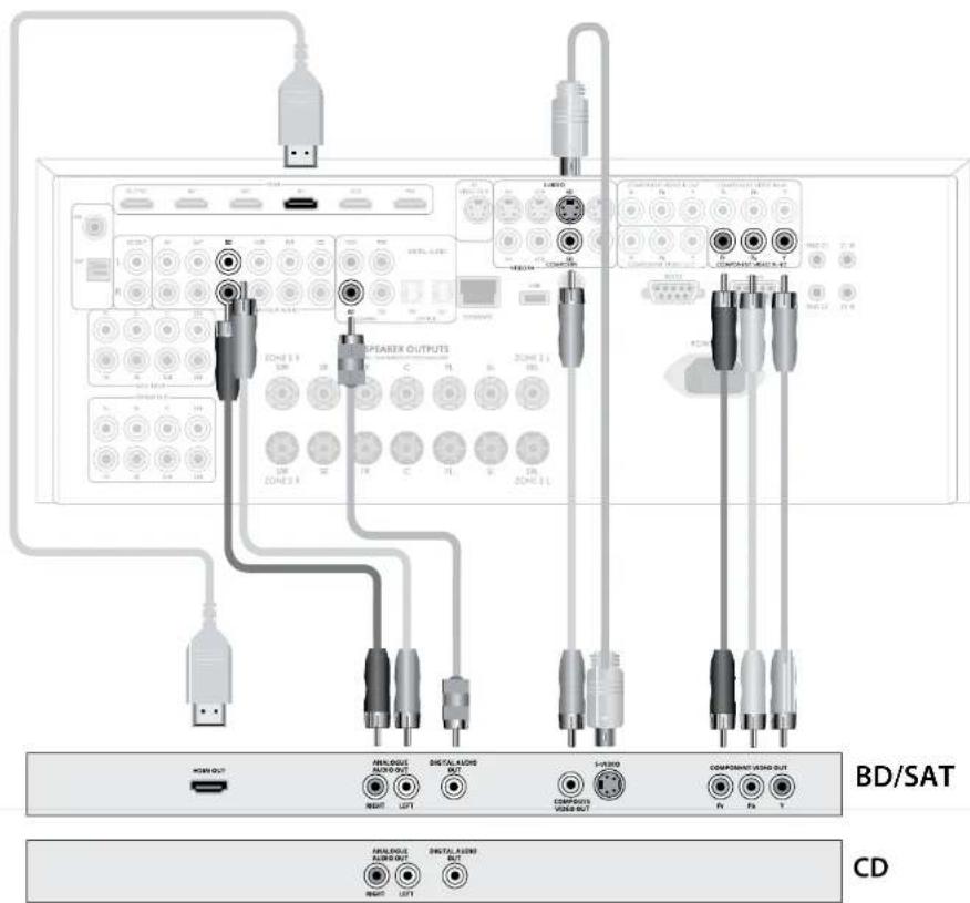
Blu-ray Disc (BD) / DVD player
The diagram shows how to make audio and video connections from a typical BD/DVD player.
The preferred video hook-up, in order of preference is:
- use the HDMI connector (if HDMI output is provided by the player), otherwise connect the three Component or four RGB+Sync video connectors.
- use the S-Video connection if HDMI or Component 1RGB+Sync outputs are not provided by your player.
- use the Composite connection if HDMI.
Component/RGB1 Sync or S-Video are not provided by your player.
In each case, connect the video inputs labelledBD on the AVR360.
The preferred audio hook-up is using the coaxial digital connector (usually marked DIGITAL AUDIO OUT), in addition to the coaxial analogue outputs for left and right channels.
In each case, use the audio inputs labelled@D on the AVR360.
Satellite receiver
A satellite receiver is connected in the same way as a BD player, with the same order of preference according to the outputs provided by the satellite receiver.
In each case, use the inputs labelledSAT on the AVR360. Note that digital audio input from a satellite receiver sometimes requires a coaxial/TOSLINK (digital connector) interconnect cable, as some satellite receivers do not implement audio over HDMI properly or at all.
CD player
Connect the digital audio output (if provided by the CD player) to the digital CD input of the AVR360, using a high quality coaxial interconnect cable.
Connect the right and left analogue audio outputs of the CD player to the analoguesCD inputs of the AVR360, using a pair of high quality coaxial interconnect cables.
NOTE:
For each input, you must set the "Audio Source" setting according to the connection type. (see "Input Config." on page E-35)
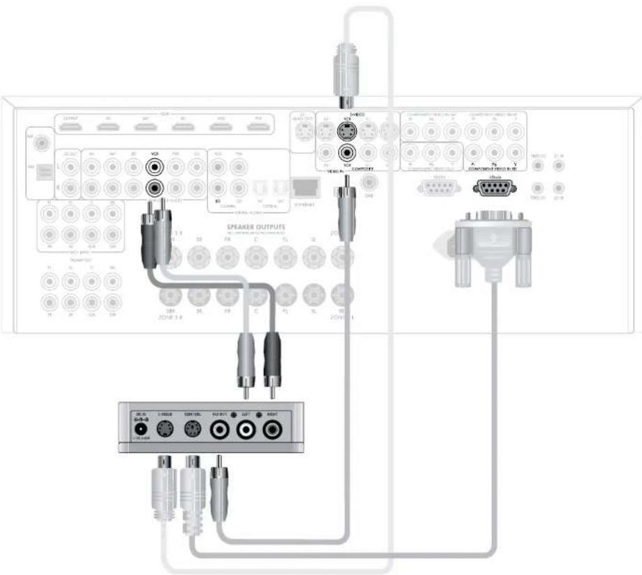
Connecting an iPod using the Arcam irDock
The combination of the AVR360 and Arcam's optional irDock or drDock accessory provides a great platform for your iPod.
Connect the irDock as shown, power on the irDock, slot in your iPod and select iPod as the source. Note that the default input is VCR but this can be changed in the General Setup menu.
Navigating through music and podcasts on your iPod is simple using the CR102 remote, with text appearing on the AVR360 display.
More information is given in the irDock quick start guide (or drDock quick start guide) supplied with these accessory units.


Aerial connectors
The AVR360 is fitted with an AM/FM receiver module and a DAR receiver, depending on the region where it was sold. The type of aerial you need depends on your listening preferences and the local conditions.
Your AVR360 is capable of superb radio reception, but only if it is receiving a good quality transmission signal. Try the aerials supplied with your unit. If you are in a medium to strong signal area, these should be adequate for good reception. In areas with poor signal strength, you may require a roof or loft mounted aerial.
Contact your local Arcam dealer or aerial installation experts for advice about local reception conditions.
DAB
(where fitted)
In strong signal areas, the DAB T wire aerial supplied can be used with reasonable results. Mount the aerial as high up as possible on a wall. In the UK the
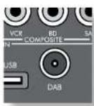
T elements need to be positioned vertically for DAB reception since broadcasts are
vertically polarised. In other localities, check with your Arcam dealer or try both horizontal and vertical positions for best reception.
Try each usable wall of the room to see which gives best reception and use tacks or adhesive tape to secure the aerial in a T shape, but note that no tacks should come into contact with internal wire of the aerial.
When installed and receiving DAB, check the signal strength by pressing the front panel or remote control's INFO button until the signal quality indicator is displayed.
In weak signal areas, a high-gain, externally-mounted or roof-mounted aerial is desirable in order to receive the highest number of services. In Band III transmission areas (such as the UK), use a multi-element Yagi aerial with the elements mounted vertically, as the transmissions are vertically polarised. If you are close to more than one transmitter, use an omnidirectional or folded dipole aerial.
If the DAB services in your area are transmitted on L band, then ask your dealer for advice for the best aerial to use.
FM
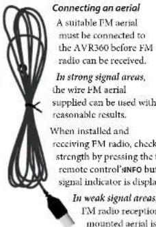
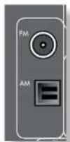
In some areas, cable radio may be available or, in an apartment building, a distributed aerial system may be installed. In either of these cases you should have sockets in your home marked FM or VHF (do not use those marked TV); these should be connected to the FM coaxial connector on the rear of the AVR360.
AM
Connecting an aerial
An AM aerial is required to receive AM/medium wave radio signals, so a simple loop aerial is supplied with the AVR360. Follow the assembly instructions in the diagram below.
Make sure that the aerial is positioned well away from the AVR360 itself, IVs, computers and other sources of RI 'interference'. Rotate the aerial to discover which position gives the best reception.

- Connect the lead wires to the AM socket at the rear of the AVR360 (the wires are not polarised). Rotate the aerial's stand until you obtain the best reception.

- Push the tab into the open slot in the base of the stand. Press until the tab clicks home.
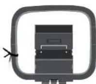
- Release the tie-wrap and unwind the twisted lead. Fold the plastic stand forward through the loop frame.

Data connectors
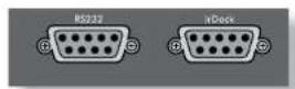
drDock/irDock
For use with an Arcane drDock or IrDock accessory. See page E-15 and the accessory documentation for details.
RS232 serial connector
Use with control devices having an RS232 serial port (for example, Crestron and AMX (touch screen controllers).
Network connector
This section deals with installation of the unit into an existing home network. For information on how to use the AVR360's network features, the USB socket, and for a list of supported file types, refer to page b.45.
Networking is a large subject and only the briefest guidelines are presented in this handbook. Please contact your Arcam dealer or specialist installer for more information about introducing the AVR360 into your computer network
Ethernet
If an Ethernet cable is connected, the AVR360 will automatically attempt to connect to your network.
You should use CAT5 cable plugged into the RJ45 socket labelled ETHERNET on the rear panel.
If your network uses static IP addressing rather than DHCP, you will need to provide IP address, gateway, DNS and proxy information. See page E-39 for information on setting up the network.
USB connector
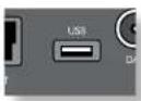
The AVR360 can play files stored on a USB mass storage device, typically a pen drive, but any USB device that complies with the 'mass storage device' class is compatible.
The AVR360 only supports the direct connection of USB devices and will not support devices connected through a hub. If regular access to the USB socket is required, you may find it convenient to use a USB extension lead. See page F-45 for details of supported file types.
Trigger connectors
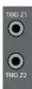
The trigger connectors (TRIG21 and TRIG22) provide an electrical signal whenever the AVR360 is switched on and the relevant zone enabled.
The trigger signal can be used to switch on and off compatible pieces of home entertainment equipment, for example, you could set up a trigger to turn on your television and BD player whenever the
AVR360 was switched on.
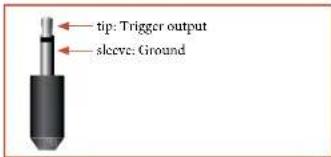
There are two trigger output sockets on the AVR360, each capable of outputting a 12V, 70mA switching signal. The socket is designed for mono 3.5mm jacks: tip is the trigger output, sleeve is ground.
TRIGZ1
Use for remotely turning on and off power amps or source equipment for Zone 1. On - 12V, Off - 0V.
TRIGZ2
Use for remotely turning on and off power amps or source equipment for Zone 2. On = 12V, Off = 0V.
Infra-red (IR) connectors
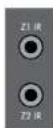
The infra-red inputs (21 IR and 22 IR) allow the connection of external IR receivers, either when the AVR360 front panel IR receiver is fully or partially obstructed or to allow the use of a remote control in Zone 2.
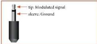
There are two IR inputs on the AVR360, each designed for stereo or mono 3.5mm jacks. Tip is the modulated signal, sleeve is ground,
NOTE
Sockets referring to 72 relate to connections used in multi-room installation. For more information on these connectors, see page E-46.
Z1IR
This input is intended for use with a local IR receiver when the front panel of the AVR360 is blocked.
Connecting an IR receiver to Z1 IR will disable to front panel IR receiver to prevent problems with multiple commands if the front panel IR receiver is only partially obstructed.
Z2IR
This input is intended for use with an IR receiver in Zone 2 to allow remote control of AVR360 from a second room.
A supplier of infra-red receivers and emitter accessories and systems is Xantech. See www.xantech.com for more information, or ask your Arcam dealer.
NOTE
The IR inputs on the AVR360 are designed for modulated signals. If the external IR receiver demodulates the IR signal, it will not work. Also the AVR360 does not provide power for external receivers on the IR jack, therefore an external power source will be required.
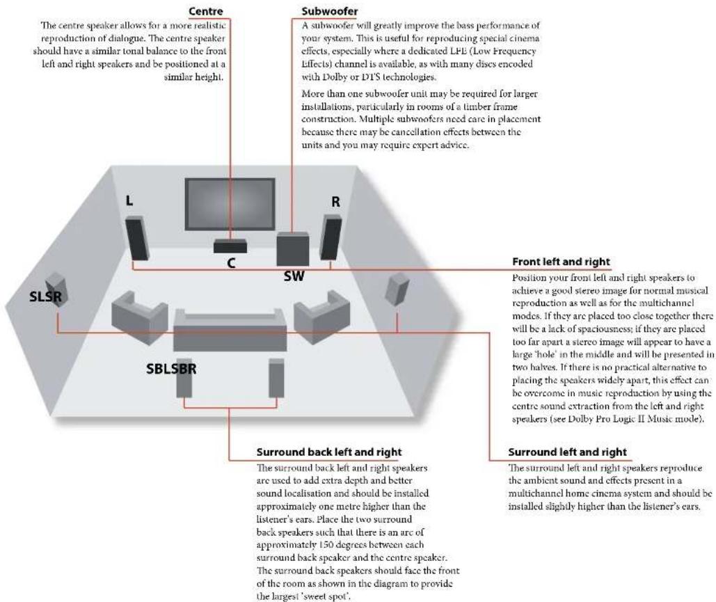
speakers
The AVR360 allows you to connect up to seven speakers and an active subwoofer in the main system. The output channels correspond to speakers installed in the front left, centre, front right, surround left, surround right, surround back left, surround back right and an active subwoofer.
The configuration and placement of your speakers is very important. All speakers, with the exception of the subwoofer, should be arranged around your normal viewing/listening position. The subwoofer should be placed in a position which gives an even frequency response in all listening positions. Incorrect placement leads to bass boom in some areas. Often the only way to find a good position for your subwoofer is by experimentation. A good place to start experimenting is close to a wall but at least 1m away from any corners. You can also consult your subwoofer handbook for placement suggestions.
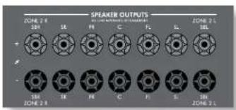
Connecting speakers
To connect each of the speakers, unscrew the corresponding terminals on the back of the AVR360, insert the speaker wires through the hole in each post and screw the terminals back up. Make sure that the red (positive/+) terminal of the speaker is connected to the red (positive/-) terminal on the back panel, and the black (negative/-) terminal of the speaker is connected to the black (negative/-) terminal on the back panel.
It is important that no stray strands of wire from these connections are allowed to touch another cable or the product casing. Failure to ensure this can cause a short circuit and damage your AVR360.
Do not over-tighten the loudspeaker terminals, or use a wrench, pliers, etc., as this could damage the terminals and this would not be covered under the product's warranty.
Speaker cables
The speakers should be connected to the amplifier using good-quality, high-purity, low impedance copper cables. Cheap speaker cables should be avoided - they are a false economy and can significantly degrade the sound quality.
The cable runs to the speakers should be as short as practicable. Connections to the speaker terminals should always be finger tight, whether using bare wires or spade connectors.
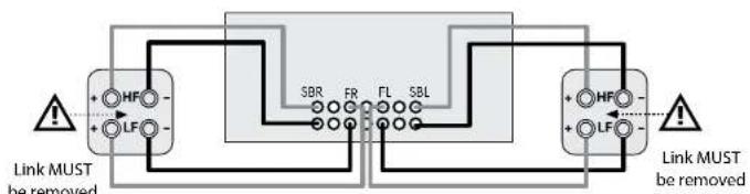
Bi-Amping the Front Left & Right speakers
Bi-amping is the use of two amplifier channels per speaker. Bi-amping can provide better sound quality than conventional single wiring. If you do not have Surround Back speakers (i.e., you have a 5.1 surround system, not a 7.1 system) then you can use the spare Surround Back speaker outputs to bi-amplify the front left and right speakers, if your speakers support bi-amping. The spare channels can alternatively be used to power stereo speakers in another room (Zone 2).
Speakers that support bi-amping have two sets of 1/ terminals per speaker, usually linked together by metal strips. These metal strips must be removed when bi-amping failure to remove them will result in damage to the amplifier that is not covered under warranty.
To bi-amp the front left and right speakers, remove the metal strips from the speaker terminals. Connect the woofer or LP terminals to the FL and FR terminals on the AVR360. Connect the tweeter or HF terminals to the SBL and SBR terminals on the AVR360. Finally, navigate to the Setup Menu "Spkr Types" and set the "Use Channels 6+7 for" menu option to "BiMp L+R" - see page F-32.
Connecting subwoofoers
The AVR360 also allows an active subwoofer to be connected to the SUB output.
See your subwoofer handbook for the correct setting up and connection for your particular subwoofer.
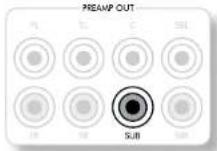
Using external power amplifiers
The internal power amplifier of the AVR360 can be supplemented or replaced with external power amplification. Connect the PREAMP OUT sockets to your power amplifier inputs:
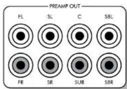

FL,FR,C
Connect these to the equivalent (Right, Left and Centre) front channels of your power amplifier.
SUB
Subwoofer output. Connect this to the input of your active subwoofer, if present.
SR, SL
Surround Right and Surround Left outputs. Connect these to the Surround Right and Left power amplifier inputs.
SBR, SBL
Surround Back Right and Surround Back Left outputs (only used in 7.1 channel systems). Connect these to the Surround Back Right and Surround Back Left power amplifier inputs.
All pre-amplifier analogue outputs are buffered, have a low output impedance and are at line level. They are able to drive long cables or several inputs in parallel if required.

Operating your AVR360
For information display we recommend you use the OSD (On Screen Display) on your display device whenever possible.
Switching on
Press the front panel power button in. The power LED will glow green, the front display shows the word 'PACRT'. When initialisation is complete, the display shows the volume setting and the name of the selected input.
Please wait until the unit has finished initialising before operating the AVR360. It is recommended that if the unit is switched off, you will wait at least 10 seconds before switching the unit back on.
Standby
The AVR360 has a standby mode which can be entered by pressing STANDBY on the remote control. When in standby mode, the display is blank and the POWER LED glows red.
If the unit is to be left unused for an extended period, we recommend that you disconnect it from the mains supply to save power.
To switch on from standby
Press the STANDBY button on the remote control or any key on the front panel (other than the power button).
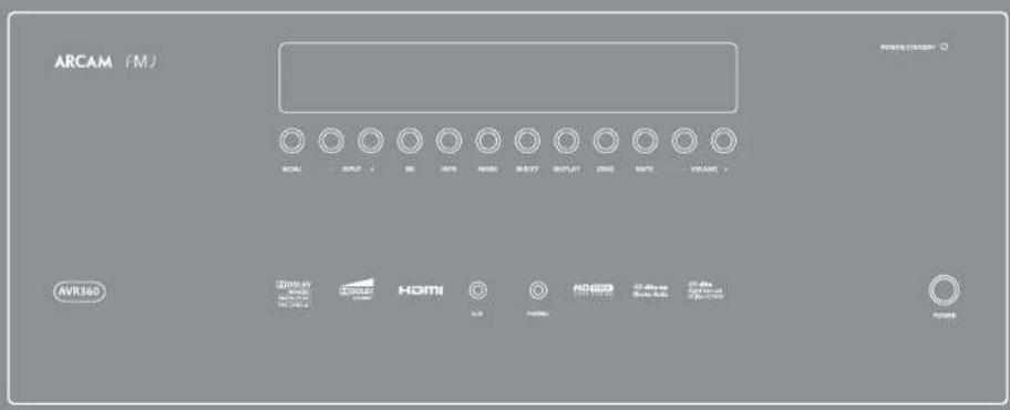
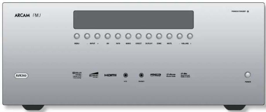
Front panel display
The AVR360 is ready for use after about four seconds.

The display window shows the currently selected source and the last selected information view setting (this information line can be changed using the INFO button). The current volume setting for Zone 1 (37.0dB in the above example) is displayed on the front panel. The volume setting for Zone 2 is displayed temporarily whenever it is adjusted.
Selecting a source
To select a particular source, press the INPUT or INPUT+ buttons until that source is shown on the front panel display, or (if available) press the corresponding source button on the remote. The following sources are available:
| CD | Compact Disc player input |
| BD | Blu-ray Disc player input |
| AV | Audio-Visual input |
| SAT | Satellite receiver input |
| PVR | Personal Video Recorder input |
| VCR | Video Cassette Recorder input |
| IPOD | Requires an iPod* and Arcam irDock or drDock |
| AM | Internal timer input |
| FM | Internal timer input |
| DAB* | Internal timer input |
| NET | Internal (Ethernet) and external USB solid-state device (e.g. pen drive) input |
| MCH | Selects MCH (multi channel) analogue input |
| AUX | Auxiliary (front panel) input |
| DISPLAY | The Audio Return Channel (ARC) from an HDMI 1.4-compliant display. Use this with an HDMI 1.4-compliant television using internal TV tuners. |
Most audio inputs have both analogue and digital connections. You must specify the type of connection used for each input using the "Audio Source" option in the "Input Config." menu, see page B-35. Note that an incorrect setting will result in no sound - the default is IIDMI audio. If you are not using IIDMI audio then this setting must be changed.
The processing mode and Stereo Direct functions are remembered and recalled for each individual input. The MCH input is intended for direct analogue pass-through of DVD-Audio or SACD sources. Apart from volume control and level trim, no processing modes are possible on this input, including AVR360 bass management and delays. Please set bass management, speaker size and speaker delays in the source player. You
can copy the distances and relative speaker levels from the Setup menus in the AVR360.
Stereo Direct
To listen to a pure analogue stereo input, press the DIRECT button. The Stereo Direct mode automatically bypasses all processing and any surround functions. In direct mode, digital processing is shut down to improve the sound quality and reduces digital noise with the AVR360 to an absolute minimum.
Note: when Stereo Direct mode is selected, no digital output is available and no bass management is performed, meaning that bass signals will not be redirected to a subwoofer.
Volume control
It is important to realise that the level of the volume indicator is not an accurate indication of the power delivered to your loudspeakers. The AVR360 often delivers its full output power long before the volume control reaches its maximum position, particularly when listening to heavily recorded music. In comparison, some movie sound tracks can appear very quiet, as many directors like to keep maximum levels in reserve for special effect sequences.
Headphones
To use headphones with the AVR360, plug the headphones into the PHONES socket in the centre of the front panel.
When headphones are plugged into the front panel PHONES socket, the outputs for Zone 1 are muted and the audio will be down-mixed to two channels (2.0). The two-channel down-mix is required so that the centre channel and surround information can be heard via the headphones.
Using Zone 2
Zone 2 provides the option for the occupants of the master bedroom, conservatory, kitchen, etc. to view or listen to a different source at a different volume level from the main zone (Zone 1).
Source selection and volume control for Zone 2 is achieved either by using an IR receiver in Zone 2 (see "Zone 2 control connections" on page L-46) or by switching over to Zone 2 control by pressing the front panel zone button or by pressingAMP followed by SHIFT then Ok on the remote control. The front panel VPD display indicates that control has been switched to Zone 2.

To turn on Zone 2, press the Zone button (or shift ok) then press the standby power button on the remote control. Press a source select button to select a different source to Zone 1.

Note that Zone 2 control from within Zone 1 will pass automatically back to Zone 1 control after a few seconds of inactivity.
Zone 2 can also be controlled using a third-party programmable remote control or a home automation system. Please contact your dealer or installer for further details.
Extended front panel menu
Pressing the MENU key and holding it for longer than four seconds will bring up the Extended Menu, allowing you to perform the following:
Restore to factory defaults
This option allows you to restore all settings on your AVR360 to the defaults that it left the factory with.
Change remote code
The default RC5 system code the AVR360 responds to is 16. If required, for example due to another device in your system also using this RC5 system code, it can be changed to 19.
This option allows you to restore all settings to their state as saved using the 'Store secure backup' feature. This option is useful if settings are accidentally changed. It also allows the unit to be returned to the saved state following a firmware update.
Store secure backup
This option allows you to save all the AVR360 settings to a secure area of memory. The settings can be retrieved using the Restore option above.
-Enter PIN
Enter the secure backup PIN using the and keys on the remote control (do not use the numeric keypad). The default PIN is 1234.
-Change PIN
Allows the PIN to be changed to a number other than the default. Enter the current secure backup PIN using the and keys on the remote control (do not use the numeric keypad). The default PIN is 1234. After the current PIN has been entered correctly, enter a new PIN as prompted and again to confirm.
-EXIT
Cancel and return to the extended menu.
Updating firmware via USB
The firmware in your AVR360 can be updated using a USB flash drive containing a firmware update file.


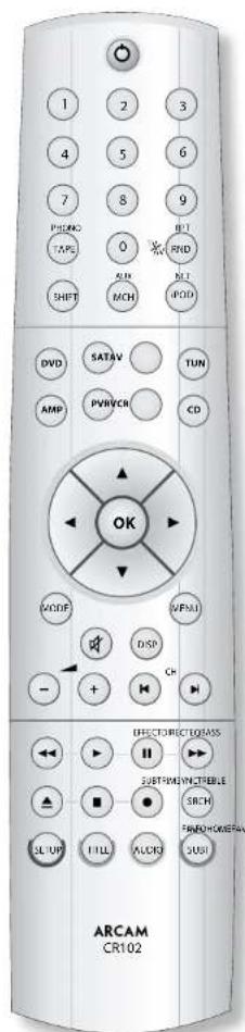
The CR102 universal remote controller
The CR102 is a sophisticated 'universal' backlit remote control that can control up to eight devices. It is preprogrammed for use with the AVR360 and many other Arcam products (FM/DAB tuners, CD players and DVD players).
With its extensive built-in library of codes, it can also be used with thousands of third party audio-visual components - TVs, satellite and set-top boxes, PVRs, CD players, etc. See the list of codes at the back of this handbook, beginning on page 56.
The CR102 is a 'learning' remote, so you can teach it almost any function from an old single-device remote. You can also program the CR102 to issue a sequence of commands ('macros') from a single button press.
Using the remote control
Please keep in mind the following when using the remote control:
Ensure there are no obstacles between the remote control and the remote sensor on the AVR360. The remote has a range of about 7 metres. (If the remote sensor is obscured, the Z1 IR remote control input jack on the rear panel is available. Please consult your dealer for further information.)
Remote operation may become unreliable if strong sunlight or fluorescent light is shining on the remote sensor of the AVR360.
Replace the batteries when you notice a reduction in the operating range of the remote control.
Inserting batteries into the remote control

- Open the battery compartment by pressing the button on the back of the handset.
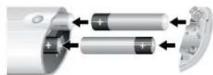
- Insert four AAA batteries into the battery compartment - two facing the top of the unit, and two facing the end, as in the diagram.
- Lower the end cap onto the plastic locating plate in the handset. This acts as a hinge, and you can now push the end cap firmly into its locked position with a click.
Notes on batteries:
Incorrect use of batteries can result in hazards such as leakage and bursting.
Do not mix old and new batteries together.
Do not use non-identical batteries together - although they may look similar, different batteries may have different voltages.
Ensure the plus (+) and minus (-) ends of each battery match the indications in the battery compartment.
Remove batteries from equipment that is not going to be used for a month or more.
When disposing of used batteries, please comply with governmental or local regulations that apply in your country or area.
Useful information
Backlight
A blue backlight comes on for five seconds whenever a key is pressed. This helps you use the handset in subdued lighting conditions. It may be possible to hear a quiet tone being emitted from the remote control when the backlight is on. This is perfectly normal.
PowerLEDblinks
Short blinks indicate a valid key press.
Multiple short blinks convey information (such as a device code) or signal the beginning and successful completion of a programming sequence.
Long blinks indicate an invalid key press or entry. The symbol 品 is used in the manual to indicate a power LED blink.
Timeouts and unassigned keys
Time out - After 10 seconds the CR102 exits the programming state and returns to normal operation.
Stuck key timeout - After any key is pressed continuously for 30 seconds, the CR102 stops sending IR transmission to conserve battery life. The CR102 remains off until all keys are released.
Unassigned keys—the CR102 ignores any unassigned key presses for a particular Device Mode and does not transmit IR.
Low voltage indicator
When the batteries are running down, the IR transmit indicator on the CD102 (the LED under the Power button) flashes five times whenever you press a button:
If this happens, please fit four new AAA alkaline batteries as soon as possible.
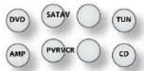
Device Mode / Source keys
As the CR102 can control your AVR360 as well as a range of other equipment, many of the buttons have more than one function depending on the device mode selected on the remote control.
The Device Mode keys (shown below) select the source on the AVR360. If one of these keys is pressed briefly, a command is transmitted to change the source on the AVR360. Also the functionality of the remote control changes to operate the selected source device. It's like having eight different remotes in your hand!

| DVD | DVD player or Blu-ray Disc player |
| SAT | Satellite set-up box |
| AV | Audio-visual sound input (use with TV) |
| TUN | DAB, FM or AM timer |
| AMP | Controls the amplifier and setup features of the AVR360 |
| PVR | Auxiliary input, or an iPod via an Arcam irDock or drDock |
| VCR | Personal Video Recorder (or Digital Video Recorder) |
| CD | Compact Disc player |
If you press and hold a Device Mode key for about four seconds, you change the Device Mode of the CR102 without changing the signal source on the AVR360. This can also be done by pressing followed by a Device Mode key (within two seconds). These two methods allow you to change which device the CR102 controls without also changing the AVR360 source, allowing uninterrupted listening.
Each Device Mode changes the behaviour of many of the CR102 keys to control the source device appropriately. For example:
In CD mode plays the previous CD track.
In AV mode issues the TV channel down command.
The CR102 remains in the last selected Device Mode so it is not necessary to press a Device Mode key before every command key if all you are doing is playing or skipping tracks on a CD, for example.
Navigation keys
The Navigation keys steer the cursor in Setup menus or on-screen menus. They also replicate the navigation functions of original remotes supplied with other home entertainment devices in your system. OK confirms a setting.
Volume control
By default, the CR102 is set up so that the volume control buttons always control the volume of the AVR360, regardless of which Device Mode the remote is currently set for. This is known as volume 'punch through'.
For example, if you are listening to a CD, you will probably have the CR102 inCD Device Mode to control the CD player. You can use the volume controls on the remote directly to adjust the volume of the AVR360 without having to press to put the remote into AMPC device Mode. The volume buttons 'punch through' the CD Device Mode on the remote to the AMPC device Mode. Volume 'punch through' can be disabled individually for any device Mode if desired.
The CR102 complies with Part 15 of the FCC rules
This equipment has been tested and found to comply with the limits for a class B digital device, pursuant to part 15 of the FCC Rules. These limits are designed to provide a reasonable protection against harmful interference in a residential installation. This equipment generates, uses, and can radiated radio frequency energy and if not installed and used in accordance with the instructions, may cause harmful interference to radio communications. However, there is no guarantee that interference will not occur in a particular installation. If this equipment does cause harmful interference to radio or television reception, which can be determined by turning the equipment off and on, the user is encouraged to try to correct the interference by one or more of the following measures:
Reorient or relocate the receiving antenna. Increase the separation between the equipment and receiver.
Connect the equipment into an outlet or a circuit different from that to which the receiver is connected.
Consult the dealer or an experienced radio/TV technician for help.
Controlling other devices
Method 1 (Direct code setup)
This section describes the simplest (preferred) way to program the CR102's Device Mode keys to control the non-Arcam devices in your system.
Some of the modes are locked to Arcam operation but can be unlocked if required (see page E-50).
mode only controls Arcam equipment.
| BD mode Locked |
| SAT mode Unlocked |
| AV mode Unlocked |
| TUN mode Locked |
| VPR mode Locked |
| VCR mode Unlocked |
| CD mode Locked |
Here is a specific example of how to program the key to control an Addison television. The principles for controlling other devices are exactly the same.
- Make sure your device is switched on (not just on standby).
- Find the correct Device Code table (e.g. TV) for the type of device you want to control from the CR102.
- Find the row containing the codes for the manufacturer of your device (e.g. Addison) (page 56). The most popular code is listed first.
- Press the appropriate Device Mode key (e.g. ) on the CR102.
- Press and hold until the red power LED blinks twice: (If actually blinks once when you press the key, then twice after about three seconds).
- linter the first four-digit device code using the number keys. The power key blinks (wice; ..
- Aim of the CR102 at the device and press () . If the device switches off, the setup is complete.
- Turn your device back on and test all the CR102's functions to ensure they are working properly.
- Important! Write your device code down on the right hand side of the page so you can remember it if you ever reset the CR102.
What if I still can't control my device?
If your device doesn't respond, repeat the above steps until one of the device codes listed for your brand works.
If none of the codes listed for your brand operates your device, or if your brand is not listed at all, try the Library Search Method described in the next section.
Notes:
Some codes are quite similar. If your device does not respond or is not functioning properly with one of the codes, try another code listed under your brand.
If your device's original remote control does not have a (POWER) key, press instead of when setting up your device.
Remember to press the corresponding device key before operating your device.
Many TVs do not switch on pressing. Please try pressing a number key ('channel select') to switch your TV back on.
To search for the code for another device follow the instructions above, but press the appropriate device key instead of 空 during step 2.
Method 2 (Library search)
This section describes another way to program the CR102 to control third-party equipment.
Library Search allows you to scan through all the codes contained in the CR102's memory. It can take a lot longer than the previous method, so only use this method if:
Your device does not respond to the CR102 after you have tried all the codes listed for your brand.
- Your brand is not listed at all in the Device Code tables.
Example: To search for a TV code
- Switch your TV on (not standby) and aim the CR102 at it.
- Press on your CR102.
- Press and hold until the power LED blinks twice.
- Press⑨⑩①. The power LED key blinks twice:
- Press
- Aim the CR102 at your Television and press repeatedly until your Television turns off.
Every time you press the CR102 sends out a POWER signal from the next code contained in its memory. In the worst case, you may have to press this key up to 150 times, so patience is required! If you skip past a code, step back by pressing. Remember to keep pointing the CR102 at your Television while pressing this key.
- As soon as your television turns off, press to store the code.
Notes:
Many TVs do not switch on by pressing Try pressing a number key (channel select) to switch your IV back on.
If you cannot control your 1 television properly, please continue the Search Method: you may be using the wrong code.
To search for the code for another device follow the instructions above, but press the appropriate Device Mode key instead of during step 2.
If your device's original remote control does not have a (STANDBY) key, press instead during step 5.
Code blink-back
Once you have set up your CR102, you can blink back your device set-up codes for future reference.
Example: To blink back your Television code
-
Press the appropriate Device Mode key (e.g., oncc).
-
Press and hold until the red Power LED blinks twice, (It actually blinks once when you press the key, then twice after about three seconds).
- Press 9 9 0 The key hinks twice.
- For the first digit of your four-digit code, press ① and count all the red blinks. If there are no blinks, the digit is '0'.
5.For the second, third and fourth digits, repeat the previous step,pressing23 or4 in order. Now you have the four-digit code.
Make a note of the codes
Write down the codes for your devices in the boxes below for future reference.
| Device Code | |
| 1 | |
| 2 | |
| 3 | |
| 4 | |
| 5 | |
| 6 | |
| 7 | |
| 8 |

AMP Device Mode
The Device Mode button configures the CR102 to control the AVR360. Pressing this button does not affect the currently selected input on the AVR360.
IMPORTANT: The CR102 must also be inAMP Device Mode to control the following sources: MCH (multichannel analogue), AUX, NET (optional network audio), USB, IPOD (for use with the optional Arcam drDock or irDock).
However to control the internal Tuner (AM/FM/DAR (if fitted)) the CR102 must first be INFUN Device Mode (see later).
The functionality of the CR102 is context sensitive for the internal sources and is described in the following table.
Single press - Toggles AVR360 power between standby and on in the current zone (zone in which the command is received). Press and hold - Forces all AVR360 zones into standby, regardless of which zone the command was received in.
0.9 The number keys can be used for source selection (without changing the CR102 Device Mode). Alternatively the Device Mode buttons can also be used with the SHIFT key.
SAT (satellite) input
②AV input
TUNER input
BD input
DISPIAy input
⑥VCR input
⑦CD input
8AUX(front panel) input
MCH (multichannel) input
01: Selects the Display input on the AVR360
02: (television Audio Return Channel).
(foIPOD and NET sources)
Modifies many keys (see individual key descriptions below).
Selects MCH (multichannel) input on the AVR360
Shift + (w) selects AUX input on the AVR360
NET Selects POD input on the AVR360 SHIFT ^+ selects network (NET) internal input on the AVR360
Navigate menus OK confirms a setting (equivalent to Enter or Select on some remote controls) SHIFT 1 increases the picture resolution. SHIFT 1 turns current zone (in which command is received) on SHIFT + turns current zone (in which command is received) off.
Cycles through the available surround and downmix modes.
43 Displays the ARV360 setup menu on the On Screen Display (see page E-34).
Cycles through the front panel display's brightness options
Toggles the mute function of the AVR360.
( track control forPOD and NET sources)
SHIFT + Follow Zone1 source.
When the command is received in Zone2 the source for that zone follows whatever input source is selected in Zone1.
Decrease - and increase () AVR360 volume
Stereo direct on/off. Provides a direct analogine path from the analogue inputs to the left and right front outputs. Switches off any surround processing modes and shuts down the DSP circuits for the best stereo sound quality.
D Displays the room EO settings menu
(1)(10000000000000000000000000000000000000000000000000000000000000
Calls up a pop-up (and front screen) to adjust the base setting for a particular input.
Brings up the speaker trim menu.
Use the, and navigation buttons. Press TRIM again to exit the speaker trim menu.
As this is a temporary adjustment, these additional trim levels are reset back to the values set in the Speaker Levels menu when the unit is turned off or the unit is put into standby. These temporary trim levels override the speaker levels found in the setup menu.
Dlays may be introduced into the video signal by video processing which causes a mismatch between the audio and video timing. You will notice this by speech sound being out of synchronization with the lip movements in the video.
To compensate for this, you can adjust the lip sync delay. Press the sync button and use the and navigation buttons. Press again to exit the lip sync trim menu.
30 Brings up a temporary subwoofer trim control.Use theand navigation buttons. Press SUB again to exit the sub trim menu.
As this is a temporary adjustment, the sub trim level is reset back to the value set in the Speaker Levels menu when the unit is turned off or the unit is put into standby.
Calls up a pop-up (and front screen) to adjust the treble setting for a particular input.
w+ (for iPOD and NET sources)
(for iPOD and NET sources)
BDC (for NET source)
Cycles through the information displayed on the lower left portion of the front panel display.
Pod commands
the iPod interface is selected by pressing in AMP Device Mode on the CR102. When connected to an Pod via an optional drDock/irDock, the keys below are used to navigate music files in AMP Device Mode.
Navigate the files on screen.
ok select/play the highlighted file.
Toggles random (shuffle) play of the playlist on and off.
SHIFT+O cycles through the repeat options
Selects the previous/next track in the current playlist
Begins or resumes playback at the currently highlighted track
Toggles pause and playback of the current track
Stopsplayback
Network commands
The AVR360 Network client is selected by pressing in AMPC Device Mode on the CR102.
When using the network client, the keys below are used to navigate music files inAMP Device Mode.
| Navigate the files and menus on the screen. Ok selects the highlighted file or enters the highlighted menu on the screen | |
| Toggles random ('shuffle') play of the playlist on and off SHIFT + (2) cycles through the repeat options | |
| Selects the previous/next track in the current playlist | |
| Begins or resumes playback at the currently highlighted track. | |
| Pauses the currently playing track | |
| Stops playback | |
| Adds the currently displayed radio station to favourites list when using the internet radio function | |
| Removes the currently displayed radio station from favourites list when using the internet radio function | |
| Returns navigation to the top level of the network client menus ('Home') | |
| Cycles through the information displayed on the lower left portion of the front panel display |
TUN TUN Device Mode
The Device Mode button configures the CR102 to control the timer functions of the AVR360. Pressing this button also selects TUNER as the source. When switching to TUNER from a different source, the AVR360 enters the last used timer band, be it AM / FM / DAB (if filtered). Further presses of the TUNER Device Mode button cycle through the available timer bands. Further information on the timer can be found in the 'Tuner Operation' section on page F-44.
not used)
0. Number keypad used to store and recall
presets
4 Allows selection of previously stored Tuner
prcstcs.
AM/FM Tuner: allows frequency tuning. DAB Tuner (where filled): scrolls through the channel list.
Selects (tunes to) the currently displayed preset, or selects the currently displayed DAB channel when scrolling through the channel list.
Page up to the previous 10 presets on screen
Page down to the next 10 timer presets on screen
Delete the currently highlighted preset
Cycles through the information displayed on the lower left portion of the front panel display.
DVD DVD/BD Device Mode
The Device Mode button configures the CR102 to control the functions of Arcam Blu-ray Disc and DVD players, although this can be changed (see page L-25). Pressing this button also selects BD as the AVR360 source.
Toggles power between standby and on 0 Searches for and plays the track corresponding to the key pressed 10 Selects Display input on the AVR360.
Toggles random shuffle play on and off. SHIFT ^+ cycles through the repeat options (track, disc, etc)
Modifies many keys (see individual key descriptions, below)
Selects multichannel (MCH) input on the
AVR360
SHIFT 1 selects AUX input on the
AVR360
Selects IPOD input on the AVR360. SHIFT ^+ selects network (NET) internal input on the AVR360
Navigaic setup and BD programmec selection memus.
Ok confirms a setting (Enter'or"Select on someremotes). SHIFT ^+ to switch on from standby SHIFT ^+ to switch to standby from on.
W Cycles through available surround sound modes. SHIFT ^+ MODE changes the IUDMI setting.
Activates BD player menu, if available.
Cycles through the front panel display's brightness options. SHIFT ^+ enables RPTA-B functionality
Toggles the mute function. By default this key operates the AVR360 Mute
Press and release to skip back to the beginning of the current/previous track.
Press and release to skip forwards to the beginning of the next track.
| Decrease (-) and increase (+) AVR360 volume | |
| Fast rewind. SHIFT + cycles through slow play backwards speeds | |
| Starts the playback of a BD. SHIFT + cycles through the Angle options on an Arcam BD player. | |
| Puses BD play-back. Press to restart playback. SHIFT + II cycles through Zoom options. | |
| Fast forward. SHIFT + cycles through slow forward speeds | |
| Ejects disc. SHIFT + displays speaker 'trim menu on Arcam BD players. | |
| Stop playback of a BD | |
| Start recording (on products that have this feature). | |
| Displays Search menu with Title, Track and Time options. | |
| Displays Setup menu. SHIFT + SETUP displays programming screen on Arcam BD players. | |
| Displays Title menu. SHIFT + TITLE clcares bookmark, search and program display entries on Arcam BD players. | |
| Changes Audio decode format (Dolby Digital, DTS, etc.) SHIFT + displays the 'Memory' function (Bookmarks) | |
| Cycles through BD subtitle language options, if available. SHIFT + displays STATUS INFO on Arcam BD players. |


SAT Device Mode
The Device Mode button configures the CR102 to control the functions of a satellite receiver. You will need to configure this Device Mode to work with your equipment. Pressing this button also selects SAT as the AVR360 source.
| Toggles power between standby and on Functions as original remote number key. | |
| 1...9 | Selects Display input on the AVR360. |
| ### | Toggles between the available inputs on your satellite receiver. |
| ### | Modifies many keys (see individual key descriptions, below) |
| ### | Selects multichannel (MCH) input on the AVR360. SHIFT 1 selects AUX input on the AVR360. |
| ### | Selects IPOD input on the AVR360 SHIFT 1 selects network (NET) internal input on the AVR360 |
| Navigate menus. | |
| Ok confirms a setting (equivalent to 'Enter' or 'Select' on some remotes). | |
| Controls Backup function, if available. | |
| Performs same function as on original remote, if available. | |
| On some Satellite and Cable set top boxes this key functions as the Guide key to open the EPG (Electronic Program Guide). | |
| Toggles the mute function. By default this key operates the AVR360 M | |
| Channel down | |
| Channel up | |
| Decrease (+) or increase (+) AVR360 volume | |
| Fast rwind | |
| Starts the playback | |
| II | Toggles pause of playback |
| Fast forward |
| ( not used) |
| Stop playback |
| Start recording |
| ( not used) |
| Duplicates function of RED key for some Satellite and Cable set-top boxes |
| Duplicates function of GREEN key for some Satellite and Cable set-top boxes |
| Duplicates function of YELLOW key for some Satellite and Cable set-top boxes |
| Duplicates function of BLUE key for some Satellite and Cable set-top boxes |

AV Device Mode
The Device Mode button configures the CR102 to control the functions of a television or other display device. You will need to configure this Device Mode to work with your equipment. Pressing this button also selects AV as the AVR360 source.
Toggles power between standby and on. (Some TVs require you to use a number key to turn them on.)
0.9 Functions as original remote number key - usually for channel selection.
Selects Display input on the AVR360.
W
```c
row = Toggles between the available inputs on
@3 your display device (e.g. TV/AV)
Modifies many keys (see individual key descriptions, below)
Selects multichannel (MCH) input on the AVR360,
SHIFT + selects AUX input on the AVR360.
Navigate setup and programme selection menus. OK confirms a selection (equivalent to Enter or Select on some remote).
EXIT function on some models.
Functions as original remote key, if available.
Display INI-O or OSD (On Screen Display) function, if available.
Toggles the mute function. By default this key operates the AVR360 Mute
Channel down
Channel up
Decrease(-)and increase (+) AVR360 volume.
Toggles TEXT page on/off
TEXT pagc off
Turns Programme In Programme (PIP) on, if available
| Activates PIP move, if available |
| Activates PIP swap, if available |
| Activates PIP freeze, if available |
| Activates PIP channel up, if available |
| Activates PIP channel down, if available |
| Duplicates function of RED key for Text TV |
| Duplicates function of GREEN key for Text TV |
| Duplicates function of YELLOW key for Text TV |
| Duplicates function of BLUE key for Text TV |

PVR Device Mode
The Device Mode button configures the CR102 to control the functions of a video recorder or similar device. You will need to configure this Device Mode to work with your equipment. Pressing this button also selects PVR as the AVR360 source.
Toggles power between standby and on.
Functions as original remote number key.
Selects Display input on the AVR360.
Toggles between available inputs (e.g. AV1, AV2)
Modifies many keys (see individual key descriptions, below)
Select multichannel (MCH) input on AVR360.
SHIFT 工 selects AUX input on the AVR360.
Selects iPOD input on AVR360.
NET SHIFT + selects network (NET) input on the AVR360.
Navigate setup and programme selection menus. OK is equivalent to 'Enter' or 'Select' on some remotes.
Operates the Exit function if the PVR uses this feature
Turns on the Menu function if the PVR uses this feature
Toggles display between TV and PVR
Toggles the mute function. By default this key operates the AMP Mute
Channel down
Channel up
Decrease (-) and increase (+) AVR360 volume
Fast rewind
Play
Toggles pause of playback
Fast forward
Operates the Favourites function if the PVR uses this feature.
Stopplayback
Starts recording
not used)
Duplicates function of RED key (if used)
Duplicates
Duplicates function of yEHow key (if used)
Duplicates function of BLUE key (if used).

VCR Device Mode
The Device Mode button configures the CR102 to control the functions of a video recorder or similar device. You will need to configure this Device Mode to work with your equipment. Pressing this button also selects vCR as the AVR360 source.

Toggles power between standby and on.
(1) (9) Functions as original remote number key.
mm: Selects Display input on the AVR360.
Toggles between available inputs (e.g. AV1, AV2)
Modifies many keys (see individual key descriptions, below)
Select multichannel (MCH) input on AVR360.
SHIFT1 selects AUX input on the AVR360.
M: SMIFT 4 selects network (NE input on the bVB360.
Navigate setup and programme selection menus. OK is equivalent to Enter or Select on some remotes.
Operates the Exit function if the VCR uses this feature
Turns on the Menu function if the VCR uses this feature
Toggles display between TV and VCR
Toggles the mute function, if available. By default this key operates the AMP Mute
Channel down
Channel up
Decrease (-) and increase (+) amplifier volume
Fast rewind
Play
Toggles pause of playback
| Fast forward |
| Lects tape |
| Stop playback |
| Starts recording |
| (not used) |
| Duplicates function of RED key (if used) |
| Duplicates function of GREEN key (if used) |
| Duplicates function of YELLOW key (if used) |
| Duplicates function of BLUE key (if used). |

CD Device Mode
The Device Mode button configures the CR102 to control the CD functions of Arcam CD players, although this can be changed (see page E-25). Pressing this button also selects CD as the AVR360 source.
Toggles power between standby and on.
(6).9 Functions as original remote number key.
mm: Selects Display input on the AVR360.
Toggles random (shuffle) play on and off.
SHIFT + Cycles through the repeat
options (track, disc, etc.)
Modifies many keys (see individual key descriptions, below)
Selects multichannel (MCH) input on AVR360.
SHIFT+ selects AUX input on the AVR360.
Selects IP0D input on AVR360. SHIFT ^+ selects network (NET) internal input on the AVR360.
Navigates track listings if supported by the player. OK selects the currently highlighted track if supported by the player
Changes the time display modes on Arcam CD player
not used)
Cycles through the front panel display's brightness options. SHIFT 品 enables RPT A-B functionality if supported by the player.
Toggles the mute function. By default this key operates the AVR360 Mute.
Press and release to skip back to the beginning of the current/previous track.
Press and release to skip forwards to the beginning of the next track.
Decrease · and increase (+) AVR360 volume.
Fast rewind
Play
Toggles pause of playback
Fast forward
Open/close disc tray
Stop playback
Start recording (on products that have this feature)
Scans first 10 seconds of each track on CD, if supported by the player (Audio search)
Starts Program mode
14A
not used)
w (not uscd)


essential setup
Before you use your AVR360 it is essential that you enter some information into the Setup menus about your speaker configuration. This allows the AVR360 to process any surround sound digital source to exactly match your system and give you the ultimate surround sound experience.
There are three pieces of vital information which are outlined in the sections: 'Speaker 'Types', 'Speaker Disanies' and 'Speaker Levels'.
The way you enter this information manually into the AVR360 is given later in the Setup Menus' section on page F-34. The settings can also be established automatically using the Arcam Auto Speaker Setup function. However it is important to understand why these speaker settings must be entered, which is why this section is presented first.
Speaker types
You need to set the type of speakers that you have connected to your AVR360:
Large capable of full frequency range reproduction Small not capable of full frequency range reproduction at the low frequency end None speaker not present in your configuration
'he terms 'Large' and 'Small' do not necessarily relate to the physical size of your speakers. As a rule of thumb, if a speaker cannot reproduce a flat frequency response down to about 40Hz (and very few can!) it is often better to consider them as 'Small' for setup purposes of home cinema.
When a speaker is set to 'Small', very low frequency sounds are redirected away from that speaker to a 'Large' speaker or a subwoofer, which are far better suited to reproducing these low frequency sounds.
Note that it is not possible to set all speakers to 'Small' unless there is a subwoofer in your speaker configuration. If you do not have a subwoofer, you will be forced to set your front speakers to 'Large'.
(Advanced users may wish to automatically override the 'Small' speaker setting for purely stereo music listening when not watching movies. This can be achieved in the 'Input Config.' menu - see page F-35.)
Crossover frequency
If you have set any speakers as being Small, then you will be required to set a value for the crossover frequency. This is the frequency below which signals are filtered away from these Small speakers and redirected to Large speakers or the subwoofer (if present). A frequency of 80Hz is often a good starting point, however you will probably have to experiment with different values to find the best value for your system or consult your speaker handbook.
MCH sub level
If a subwoofer is present, this setting allows for a 10dB compensation on the subwoofer output when using the MCH input as required by many DVD-A players with audio outputs.
Use Channels 6+7 for
If not used in the main zone, it is possible to assign the Surround Back channels to hi-amp the Front Left/Right channels or to provide an amplified output to Zone 2.
Speaker Distances
It is essential for the distance from each speaker to the listening position to be accurately measured and entered into the 'Setup' menu. This ensures that the sounds from the various speakers arrive at the listening position at the correct time to recreate a realistic surround effect. The distance can be entered in centimetres or inches.
Speaker Levels
Finally the levels of all the speakers in the system need to be adjusted to match each other at the listening position, again to create a proper surround effect. To help with this the AVR360 can generate a test noise for each speaker which should be measured with a sound pressure level (SPL) meter. The meter should be set to 'C' weighting and slow response. The level of noise measured at the listening position from each speaker should be adjusted on the Speaker Trims page of the Setup menu so that the meter reads 75dB SPL. It does not matter what the system volume setting of the AVR360 is before turning the test noise on as the volume setting is over-ridden for the duration of the speaker noise test.
There are several basic SPL meters on the market at reasonable prices aimed at home cinema enthusiasts. Check your local technology store, search online or ask your dealer.
If you do not have an SPL meter, you can try to adjust the noise level of each speaker by ear. In this case it is not possible to adjust the speakers to the absolute 75dB SPL volume level, but you should aim for all speakers sounding equally loud. Setting speaker test noise levels by ear is not recommended as it is very difficult to do accurately, but is often better than doing nothing at all!

There is a proprietary automatic loudspeaker setup function built into your AVR360. The Arcam Auto Speaker Setup function attempts to set all the essential speaker settings for all the speakers in your system. It also calculates room equalisation (Room EQ) filter values to remove some of the worst effects of resonant frequencies in the listening room.
Your AVR360 package is supplied with a calibration microphone, which should be inserted into theAUX jack socket on the front panel and positioned at the main listening position. This microphone picks up the special calibration tones generated by the speakers when Auto Speaker Setup is run. The AVR360 then analyses the signal and computes:
which speakers are present,
speaker type,
speaker distance,
speaker level,
crossover frequency to the subwoofer (or large from speakers if no subwoofer is present).
■ problem resonant frequencies in the room which need control by filtering.
To help the system be as accurate as possible when performing Auto Speaker Setup, there are a few guidance rules that should be followed:
■ Minimise any background sounds in the listening room and other nearby rooms.
- Close all windows and doors in the listening room.
- Turn off all fans including air-conditioning systems.
If holding the microphone in the hand rather than mounting on a tripod or similar, keep your hand and fingers still to avoid generating handling noise.
Position the set up microphone pointing upwards at roughly head height in the normal listening position. It is not necessary to point the microphone directly at the speaker generating the test tone. (It helps if you are able to position the microphone exactly where your head would normally be for listening, with the microphone in direct unobstructed view of all speakers.)
If your system includes an active subwoofer, start by setting its output level f gain control to a value halfway between maximum and minimum.
When activated, a calibration tone is played through each channel of the AVR360 in turn, including the subwoofer channel. The calibration tone cycles round each of the speakers multiple times as the different parameters are calculated. If you do not have a full 7.1
speaker configuration there will be periods of silence between some speaker channels. 'Follow the progress' information on-screen.
After all the channels have been measured, a summary of the speaker configuration will be displayed on-screen. You can then choose to accept the settings, re-measure your system again or cancel Auto Speaker Setup without storing the settings.
The Auto Speaker Setup function is found within the Setup menus, see page E-36. By default, Room EQ is not applied to any of the source inputs. You should enable Room EQ on inputs you think benefit from this feature, as required, by listening when playing typical source material through each input. This is enabled from within the Input Config menu.
While room equalisation can help to reduce problems with listening room acoustics, it is usually far better to try to solve these problems with the room directly. Proper loudspeaker positioning, acoustic wall treatments and moving the listening position away from walls should produce far better results overall. However it may be difficult to do this in a home environment, so Room LQ is your next best choice.
Problems
We advise you to look over the reported measurements on the screen following Auto Speaker Setup for any obviously incorrect results, in particular to ensure the reported speakers match your configuration and that the speaker distances to the listening position appear look roughly correct. If the results are not what you expected re-run Auto Speaker Setup.
The Auto Speaker Setup function is normally quite accurate but occasionally false results can be generated. Problems may be as a result of:
external sounds or rumbling/ handling noises picked up by the microphone
sound reflections offard surfaces (e.g窗户 or walls) close to the listening position,
very strong acoustic resonances within the room,
- obstacles (such as a sofa) between speakers and the microphone.
If you are still experiencing difficulties or you wish to have the most accurate results for ultimate surround performance, we recommend using the manual method of establishing speaker distances and levels.
Using a subwoofer
If your system includes an active subwoofer you may need to re run Auto Speaker Setup with the subwoofer output level / gain control set to a higher or lower value, if the summary screen reports problems setting the subwoofer up.
Auto Speaker Setup will attempt to choose a crossover frequency that allows the smoothest low frequency transition from the main speakers (to the subwoofer. However if this does not produce pleasing results we recommend manually trying other crossover frequencies to find something more to your preference.
See the next sections for information of how to enter or change speaker settings manually.

The Setup menus allow you to configure all aspects of your AVR360. The next few pages will go through the menu items and explain their function. The Setup menus will probably look quite daunting if you are new to setting up home cinema, but the majority of them need only be configured once when you first install the system (or if your system changes or you move house!) The only way to view the Setup menus is on your display device (TV or projector) using the on-screen display (OSD) capability of the AVR360. To view the OSD for the initial setting up, connect any of the video outputs to your display device. You do not need to have a video source connected to the AVR360 video inputs.
Entering Setup mode
To enter the setup menu, press the MENU button on the remote control or font panel. The front panel displays shows 'SETUP MENU' and the setup menu (pictured right) is displayed.
Unstable OSD menu or picture display?
The default AVR360 output video resolution when first powered up out of the box is 525-line/601Hz N1SC for analogue video and "Preferred" for digital video. This has been chosen as most display devices can synchronise to this automatically. This can be changed in the Video Outputs section of the Setup Menu.
If the output resolution and frame rate is forced to a setting your display device does not support, the picture may become unstable or may not display at all. To reset the output video resolution and frame rate to the default values to restore the display, press and hold the front panel OK button for three seconds. Alternatively, press Shift then on the remote control to cycle between different output resolutions until the picture returns.
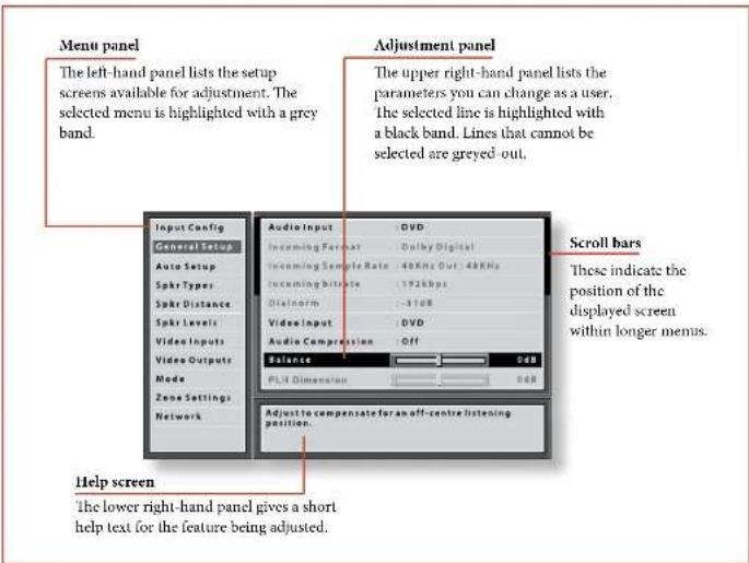
Navigating the setup menu
... using the remote control
The setup menu can be navigated by using the cursor (arrow) keys on the remote control. This is by far the easiest method.
- To enter the setup menu, press the MENU button (which is located immediately under the navigation buttons).
- Use the and keys to navigate up and down the main section headings in the left-hand panel.
- Once you have the main section that you require highlighted, use the key to enter the section.
- Use the 心 and keys to navigate up and down the section settings in the right-hand panel. Some settings may be greyed out. These are either for information only (e.g. incoming sampling
frequency) or are not currently selectable (e.g. network IP address when DHCP is used). Scroll bars on the sides of the right hand panel indicate your position in the settings list, where there are more items than can be displayed at once.
- Pressing Ok selects a setting to change it, pressing Ok again de selects the setting.
- At any time, press theMenu button to exit the menu. Any changes to settings are saved.
... using the keys on the front panel
The AVR360 front panel controls can be used to configure the unit. Follow the instructions for using the remote control, in this case using INPUT- for down, INPUT+ for up, INFO for left and Ok for right.
Input Config.
The audio and video settings on this page of the Setup menu can be tailored specifically and independently to the currently selected input.
When a different input is selected on the Input line, all the input-specific settings for that input are displayed below it. These settings are applied to the named Input only and are stored in memory and recalled each time the unit is powered up and whenever that input is selected.
Input - The currently selected input connectors to which the settings below relate.
Name - The display name of the input. You can change the name of any input to more closely match your setup. For example, if you had two satellite receivers, you could connect the main receiver to the Sat audio and video input connectors and change the Name to 'SAT 1'. You could then connect the second satellite receiver to the VCR audio and video input connectors, but change the VCR Name to 'SAT 2'. It is then clearer to users of your AVR360 which inputs they wish to select when scrolling though.
Lip Sync - Each input can have its own setting to add a time delay between the audio and video signals to compensate for the sound and picture not being synchronised. This is normally required when video processing is used in the system for scaling or dc-interlacing video. The range of lip sync delay is 0 to 250 milliseconds.
The lip sync adjustment can only correct for delayed video. If the audio is late set lip sync to its minimum.
Mode - Sets the initial audio decode mode for stereo sources on this input.
Last Mode recalls the last used setting for this input when a stereo source was applied. See section "Two channel source modes" on page B-40 for more information.
Ext. Mode Sets the initial audio decode mode for multi-channel digital sources on this input.
Last Mode recalls the last used setting for this input when a stereo source was applied. See section "Multi-channel source modes" on page F-41 for more information.
Treble - Bass -
These allow you to alter the bass and treble tone controls for all currently active speakers for each individual
input. For example, if your PVR source sounds a little bass light, you can always correct for this by selecting PVR on the Input line at the top of this menu and add 2 or 3dB to the Bass control. Then, whenever the PVR input is selected, the bass is automatically boosted for as long as that input is selected.
Room EQ- When the Auto Speaker Setup function is run it also calculates Room Equalisation coefficients to remove some of the worst effects of resonant frequencies of the room at the listening position. By default Room EQ is not applied to any of the source inputs, however you can enable them on a per-input basis as you wish.
Not Calculated: (Information only) Auto Speaker Setup has not been run or has errors so cannot be selected.
- On: Room EQ is applied to the current source.
- Off: Room FQ is not applied to the current source.
Input Trim - Sets the maximum analogue input signal level (sensitivity) on this input before the ADC (Analogue to Digital converter) signal path clips. Options are 1, 2 and 4 volts RMS maximum input. The default is 2V rms maximum.
For example, analogue sources with low output levels may benefit by choosing the 1V maximum setting. This helps maximise signal-to-noise performance of the AVR360 and also helps keep the various analogue sources sounding about the same level for any given AVR360 volume control setting.
Dolby Volume Dolby Volume is an intelligent system that improves the perceived audio frequency response at lower listening levels and corrects for volume inconsistencies between sources (e.g. a rock radio station and a BD) and between programming (e.g. a TV show and advertisement breaks).
On: Dolby Volume is applied to this input. Off: (default) Dolby Volume is not applied to this input.
Dolby Leveller This setting of Dolby Volume controls how closely quiet and loud sources and programme content are matched to each other, based on the ear's perception of loudness. The range of values is 0 (minimal levelling) to 10 (maximum levelling). The default setting is 2, however we recommend experimenting with higher values if your source material is less closely matched in level. If the Volume Leveller function is set off, no level matching between sources and programme material is performed. Note however that turning the Dolby Leveller setting of Dolby Volume to 'Off' is not the same as turning the entire
function of Dolby Volume to 'Off, as volume related frequency response processing is still active. See "Dolby volume" on page E-42 for more information.
DV Calib. Offset - The Calibration Offset parameter of Dolby Volume allows you to compensate for speaker efficiencies and listening position. The default value is 0 and this should normally produce a good result when the AVR360 speaker levels are set using a sound pressure level meter.
See "Dolby volume" on page 1-42 for further information on Calibration Offset.
Surround EX - Sets how the AVR360 should configure its decode mode when a Dolby Digital EX bitstream is received. Note that this setting only applies if you have Surround Back loudspeakers. You may wish to experiment with these two decode modes to see which you prefer with Dolby Digital EX encoded material. Options are Auto DD EX, Auto PLLx and Manual.
Auto DD EX: When a Dolby Digital EX-flagged bitstream is detected, the decode mode automatically changes to Dolby Digital EX. This can be temporarily overridden by pressing the MODE button on the remote or front panel.
Auto PLIX Movie: When a Dolby Digital EX-flagged bitstream is detected, the decode mode automatically changes to Pro Logic IIx Movie. This can be temporarily overridden by pressing the MODE button on the remote or front panel.
Manual: The received Dolby Digital EX is treated as if it is an ordinary Dolby Digital stream in that it does not automatically select the EX or PLIIx decode modes. Instead, the previously used decode mode for a multi-channel digital source on this input is applied. However, either of the EX or PLIIx decode modes can be applied manually by pressing the MODE button.
Stereo Mode - If you have configured your system to have a subwoofer, then you have the flexibility to choose how bass information is distributed between the front left/right speakers and the subwoofer when listening to stereo (two channel only) analogue and digital sources. Choose the option which gives you the most solid, even sounding bass. If you are using a subwoofer for stereo, please also see Sub Stereo below to set the level of the subwoofer. For best results test with a set-up disc or live programme material. This setting can be used to override your normal speaker settings in the Spkr Types menu whenever the AVR360 plays stereo material. It is quite common to find that two channel stereo music
listening is best done with a slightly different sub/ speaker setting than for surround movies.
As Spkr Types: When an analogue or digital stereo source is played, your normal speaker configuration (as in Spkr Types menu) is used to reproduce the signal.
Left/Right: Full frequency stereo information. All audio is sent to the front left and right speakers only without any bass redirection. You can use this setting if you consider your front left/right speakers to be able to handle the full frequency range of music. If you have set your front left/right speaker size as Small in the Spkr Types setup page, you may wish to use this option to override the setting to Large for stereo music listening, if you have full frequency range left/right speakers.
It can often be beneficial to set full frequency range speakers to Small in the Spkr Types setup page for use with movies, if you have a subwoofer in your system. Doing so may deliver more impact on movie soundtracks as subwoofer are designed to handle reproduction of high bass content. However you may find that for stereo music a better overall result is obtained by not using the subwoofer and effectively treating the front left/right speakers as Large.
Left/Right+Sub: Full frequency range stereo is fed to the front left and right speakers and extracted bass is sent to the subwoofer. In this case the low frequency information is effectively duplicated.
Sat+Sub: Use this setting if you really do have Small satellite front left and right speakers, or if you prefer the overall sound of bass being handled by the subwoofer. Full bass management is used so that analogue and digital stereo sources are fed to the DSP where the bass is filtered off front left and right and redirected to the subwoofer.
NOTE
The Stereo Mode function is not available when using an analogue source in Stereo Direct mode.
Sub Stereo - If Left/Right+Sub or Sat+Sub is selected in Stereo Mode above, this setting adjusts the level of the subwoofer when the source is two channel stereo.
Brightness - Sets the video brightness for this input. This setting can be used to compensate for an overly dark or bright source picture on this input when compared with other video sources.
Contrast - Sets the video contrast for this input. This setting can be used to compensate for too much or too little contrast in the source picture on this input when compared with other video sources.
Colour - Sets the video colour saturation for this input. This setting can be used to compensate for too much or too little colour in the source picture on this input when compared with other video sources.
Picture Mode - Sets how the video processor in the AVR360 interprets the video on this input. Normally the video processor automatically detects the original source type and correctly sets either Video mode or Film mode processing. In the unlikely event that the video processor misinterprets the video type, resulting in subtle picture artefacts, the video processor can be manually forced into Video mode or Film mode. This function should normally be set to Auto.
Edge Enhancement - Sharpens the picture from a source on this input.
MPEG N.R. - Removes artefacts in overly compressed digital video from a source on this input.
Noise Reduction - Removes random noise within the picture from a source on this input.
Component Mode - Configures the current three-wire high quality analogue video input for component (YUV) video signals or RGB video signals. It is important to match the setting to the incoming video format otherwise the colours will be incorrect and the picture may be unstable.
Options are Normal, RGsB and RGB + Sync.
Normal: (default) the three-wire input is configured for normal Component (YUV / YPhPr) analogue video.
RGSb: The three-wire input is configured for RGB analogue video with video 'sync-on-green'.
RGB+Sync: the three wire input is configured for RGB analogue video, with the video sync signal on the composite input for the current named source.
You should typically select RGB+Sync if you are using a standard SCART to 4-wire phono breakout cable to connect an RGB SCART source.
NOTE: If RGB+Sync is selected, the S-Video and Composite inputs cannot be selected as video inputs for the current source.
Video Source - Selects the video signal connection for this source. The default is HDMI; this setting must be changed if another connection is used.
- HDMI: the unit is forced to use the HDMI video input for this source.
Component: the unit is forced to use the COMPONENT/RGB video input for this source.
S-Video: the unit is forced to use the s-Video input for this source.
Composite: the unit is forced to use the COMPOSITE video input for this source.
Audio Source - Selects the particular connection type for each input. The default is HDMI; this setting must be changed if another connection is used. Select from the list the audio type you are using on this source.
HDMI: the unit is forced to use the HDMI audio input for this source.
Digital: the unit is forced to use the optical (TOSINK) or coaxial (S/PDF) digital audio input for this source
Analogue: the unit is forced to use the analogue audio input for this source.
General Setup
General information and system controls.
Source Input - (Information only) The currently selected input to which the settings below relate. Incomng Format - (Information only) The format of the digital audio stream connected to this input, if present.
Incoming Sample Rate (Information only) The sample rate of the digital audio stream connected to this input, if present.
Incoming Bit Rate - (Information only) The bit rate of the digital audio stream connected to this input, if present.
Dialnorm - (Information only) If a Dolby Digital audio stream is connected to this input, this is the Dialogue Normalisation setting requested by the stream.
Video Input - The currently selected video input. For inputs that have video connections (e.g.SAT, PVR etc), audio and video inputs normally switch over together. However, here you can temporarily select a different video source for the current audio source. This feature may be useful, for example, if you are watching a sports game on satellite but on this occasion wish to listen to the commentary on the radio instead. This temporary override is reset when the input source is changed so
that the Video Input follows the Audio Input setting (or the setting in the Video Inputs menu, if applicable).
Audio Compression - Allows selection of compression which is ideal for late night listening. The compression effect increases the volume of the quiet passages and decreases the volume of the louder passages. Compression only applies to Dolby soundtrack formats that support this function (D'IS is not supported).
Off: (default) no audio compression is applied. Medium: compression is applied so that loud portions of a soundtrack are reduced in level.
- High: the maximum amount of dynamic range compression is applied, so that the difference between loud and quiet portions of a soundtrack is minimised.
This setting applies to all inputs when a relevant digital audio stream is detected. It is stored in memory and recalled each time the unit is powered up.
Balance - To alter the sound balance temporarily between front left and right speakers. You can alter the sound stage to either the left or the right by up to 6dB. Note that it is not possible to shift the audio signal completely over to one channel. This function resets to equal left/right balance when the input is changed.
PLI Dimension -
PLI Centre Width -
PLII Panorama -
These allow the adjustment of the sound field for Dolby Pro Logic II Music mode decoding of two-channel sources. These setting apply to all inputs when PI.II or PI.IIx Music decoding is selected. The settings are stored in memory and recalled each time PI.II or PI.IIIx Music mode is selected.
PIII Dimension: Allows the user gradually to adjust the sound field either towards the front or towards the rear. Settings range from -3 to +3. We recommend Dimension is set to 0 for normal use.
PIII Centre Width: Controls the centre image width. With Pro Logic decoding, dominant centre signals come only from the centre speaker. If no centre speaker is present, the decoder splits the centre signal equally to the left and right speakers to create a phantom'centre image. The Centre Width control allows variable adjustment of the centre image so it may be heard only from the centre speaker; only from the left/right speakers as a phantom image; or from all three front speakers to varying degrees. We recommend Centre Width is set to 3 for normal use.
PIII Panorama: Extends the front centre image to include the surround speakers for an exciting 'wraparound' effect with side-wall imaging.
Digital Output Freq. - Sets the sampling frequency of the audio Analogue to Digital converter. This setting applies to all inputs when analogue audio is being processed (i.e. not Stereo Direct mode). It is stored in memory and recalled each time the unit is powered up.
Maximum Volume Limits the maximum volume setting the system can be turned up to in the main zone. This is a useful feature to prevent accidental overdriving of low power-handling speakers (for example). It is stored in memory and recalled each time the unit is powered up.
Max On Volume - Limits the maximum volume the system operates in the main zone when it is switched on or comes out of Standby. The system comes on at this stored volume setting if the last used (possibly very loud) volume exceeds this value. It is stored in memory and recalled each time the unit is powered up.
Display on time - Sets the time that the front panel display remains illuminated after receiving a command. 'The default is always on.
Audio In iPod - If you have an iPod connected to the AVR360 using an Arcam irDock or driDock, this control allows you to set which audio input is used.
CEC Control - Enables or disables HDMI CEC control, a system that allows devices connected with HDMI to control other compatible connected devices.
ARC Control - Enables or disables the HDMI 1.4 Audio Return Channel. This allows for television sound to be sent back to the AVR360, via the "Display" input.
HDMI Audio To TV - Enables or disables the transmission of HDMI audio from the HDMI output connector. Enable this setting if you wish to be able to listen using your TV speakers.
RS232 Control - Enables or disables RS232 control, a system that allows control from various third party home automation systems.
Auto Setup
Auto Speaker Setup of your loudspeakers and subwoofer (if present) is controlled by this menu. A full description of how Auto Speaker Setup works is given on page F-33. Remember to insert the calibration microphone into the AUX input on the front panel and position the
microphone at the listening position before running Auto Setup.
Run Auto Setup - Press OK (or on the remote) to start Auto Speaker Setup. The process will generate test tones from the speakers and will typically take less than two minutes. The test tone generator will cycle round each speaker twice.
Accept Setup - When Auto Speaker Setup has completed without errors you can choose to accept or reject the settings
No: The settings are not stored in memory.
Yes: All the speaker settings (speakers present, type, distance, level and crossover frequency) are stored in the relevant sections of the Setup Menu and overwrite any previous settings.
Auto Setup Progress - Gives a summary of what Auto Speaker Setup is doing as it progresses, starting with which speaker is being tested.
- Noise Level: Checking noise level relative to each speaker and subwoofer.
Number of Speakers: Speaker configuration is detected including the number of surround speakers and whether a subwoofer and center speaker are connected.
Speaker Distance: Accurately detects the appropriate distance of each speaker position as well as the subwoofer with respect to the microphone position. - Speaker Level and Size: The crossover is set based on each channel's signal handling capability and the subwoofer crossover is automatically set. The SPL (Sound Pressure Level) of each speaker is matched with respect to the microphone position.
Calculating EQ: Data gathered from each of the speakers is being processed.
Completed Error: A problem was detected with the speaker setup. See the descriptions for each of the individual speakers, below. Alternatively an invalid speaker configuration was detected.
Front Left -
Centre -
Front Right -
Surr. Right
Surr. Back Right -
Surr. Bac
Surr. Left:
Subwoofer
If the above speakers are correctly detected as present in your speaker configuration, their size (Small or Large), distance from the listening position and trim level (dB) will be displayed. Note that size does not apply to the subwoofer. Otherwise an error message will be displayed:
Not Present: A speaker was not detected on this channel.
Crossover Freq. - The frequency at which Auto Speaker Setup determined is the best point to filter low frequency sounds away from Small speakers and into the subwoofer (or Large speakers if a subwoofer is not present).
NOTE
Auto calibration is possible only for a 7.1 or 5.1 speaker configuration. For other speaker configurations such as a 2.1 (stereo + subwoofer) setup, you must complete setup manually by referring to the guidelines below for Speaker Configuration, Speaker Distance and Speaker Levels.
Spkr Types
Settings for the types of loudspeaker you have connected in your configuration. These settings are applied to all audio inputs and are stored in memory and recalled each time the unit is powered up.
Front Left/Right
Centre
Surr.Left/Right
Surr. Back L/R
Here you set the type of speakers that you have connected to your AVR360:
Large: capable of full frequency range reproduction
Small: not capable of full frequency range
reproduction at the low frequency end
None: speaker not present in your configuration
Subwoofer: Set whether a subwoofer is present or not.
NOTE
It is not possible to set all speakers to Small unless there is a subwoofer in your speaker configuration. If you do not have a subwoofer, you will be forced to set your front speakers to Large.
Crossover Freq - This is the frequency at which loudspeakers set as Small start to redirect bass signals to the Subwoofer or Large speakers in your system. Small speakers redirect bass to the subwoofer, if present. The exception is the Centre speaker which, if Small, redirects its bass to front left/right provided that they themselves are Large. This is done to help keep Centre bass directly in front of the listening position.
MCH Sub Levels - This setting controls the subwoofer level from an externally decoded multi-channel source (BD) A, SACD, etc). Most BD players require a 10dB compensation on the subwoofer channel to maintain the correct balance with the main channels.
+10dB: for normal BD players which output the analogue subwoofer channel at the low 0dB level. Gain compensation of +10dB is added to the subwoofer channel of the MCHINPUT in the AVR360.
0dB Normal: for BD players which output the analogue subwoofer channel at the correct +10dB level. No subwoofer gain compensation is needed on the subwoofer channel of theMCH INPUT in the AVR360.
Use Channels 6+7 for - If your main zone speaker set up does not include Surround Back Left and Right speakers, you can choose to use the Surround Back amplifier channels to Bi Amp the Front Lell and Right pair, or as a stereo power amplifier for Zone 2.
Spkr Distance
Calibration settings for the distances between the loudspeakers and the listening position.
NOTE
Speakers that are not present in your configuration will be greyed out.
These settings are applied to all audio inputs and are stored in memory and recalled each time the unit is powered up.
Units - Select whether you wish to measure distances in imperial or metric units.
Front Left -
Centre
Front Right
Surr. Right
Surr. Back Right -
Surr. Back Left -
Surr. Left -
Subwoofer
As described in "essential setup" on page 32, measure the distance from each loudspeaker in your system to your car in the main listening position and enter the values. This allows the AVR360 to calculate the correct relative delay for each loudspeaker.
Spkr Levels
Calibration settings for the test noise signal level
through the loudspeakers and measured at the listening position.
NOTE
Speakers that are not present in your configuration will be gregarred out.
These settings are applied to all audio inputs and are stored in memory and recalled each time the unit is powered up.
Use the and navigation buttons on the remote control to select the relevant speaker. Pres to enable/disable the calibration noise and the and navigation buttons to adjust the noise level from each speaker.
Front Left -
Centre - Front Right -
Surr. Right
Surr. Back Right
Surr. Back Left
Surr. Left -
Subwoofer
As described in "essential setup" on page E-32, adjust the level of the test noise from each speaker so that an SPL meter at the listening position measures 75dB SPL.
Video Inputs
Settings to optionally assign a video source to each of the normally audio-only inputs.
These settings are stored in memory and recalled each time the unit is powered up.
Video Input CD
Video Input Aux
Video Input AM/FM
Video Input MCH
Video Input iPod -
Video Input Net
Video In Digital Radio -
The default for each of the audio inputs is 'None', however for example you could associate the satellite 'Sat' video with AM, FM and Digital Radio audio if you wished. This way you could listen to the FM or AM or Digital Radio commentary of a sports game but have the pictures from the satellite coverage.
Video Outputs
The settings in this menu control the output resolution from the video processor in the AVR360. These settings are applied to all video inputs and are stored in memory and recalled each time the unit is powered up.
NOTE
Important points to remember:
For the analogue output
You should set the frame rate (50Hz) Interlaced for PAI, 60Hz Interlaced for NTSC) and the aspect ratio (4:3 standard or 16:9 widscreen) to match your display device.
For the HDMI output
The output resolution, frame rate and display aspect ratio can be automatically determined by the AVR360. Alternatively these settings can be manually selected.
Zone1 OSD - Selects whether the main zone pop-up OSD messages are On or Off. It is stored in memory and recalled each time the unit is powered up.
When On, all user adjustments that are made during the general use of the AVR360 are displayed on screen as well as the front panel display. This includes the adjustment of volume, subwoofer level, lip sync, tone controls, etc. It is stored in memory and recalled each time the unit is powered up.
When Off, the above user adjustments will not appear on screen, only on the front panel display. This leaves the picture on your display device clear of pop-up text. However, regardless of this setting the Setup menus are always displayed on screen.
Zone 2 OSD - Selects whether the Zone 2 pop-up OSD messages are On or Off. It is stored in memory and recalled each time the unit is powered up.
Analogue Output - This setting controls the output resolution of the analogue video output of Zone 1. The dropdown list shows all the resolutions that the AVR360 video processor can output.
Analogogue Frame Rate - This setting controls the output frame rate of the analogue video outputs of Zone 1. This setting is only valid if the HDMI output is not being used at the time. See the Note 'Important points to remember' regarding analogue frame rates.
Display Type - Set the aspect ratio of your display device; 4:3 standard or 16:9 widenscreen.
HDMI Output Resolution - This setting controls the output resolution of the HDMI output.
The dropdown list shows all the resolutions that the AVR360 video processor can output. Resolutions that are not supported by the connected display device are greyed out and cannot be selected.
-
Preferred: sets the output resolution to be the preferred resolution that is requested by the display device. This is often the highest resolution the display device can receive.
-
Bypass: this is a special mode where video passes straight through the AVR360 without alteration. Use this mode to watch 3D content on a 3D television. This mode also allows the AVR360 to output video with a 23.976Hz frame rate. The output resolution and frame rate will be identical (to the input resolution and frame rate). The display must be capable of supporting the input resolution and frame rate — if the input video format is not supported by the display there will be no picture.
Output Frame Rate - This setting controls the output frame rate of the HDMI output.
- The dropdown list shows all the frame rates that the AVR360 video processor can output. Frame rates that are not supported by the connected display device at the above resolution are greyed out and cannot be selected.
Auto sets the HDmi OUT frame rate to be the preferred frame rate that is requested by the display device for the currently used resolution.
Follow input sets the OUT frame rate to be the same as the input frame rate. Use this setting if you regularly switch between 24Hz and 50/60Hz content and have a 24p compatible TV.
Lipsync - (Information only) Displays how much lip sync is automatically applied to the HDMI output to compensate for video processing delays in the attached display device. Not all display devices support this function.
Mode
Lists the decode and downmix options you wish to include when cycling through the options on the MODE button. Settings are Yes or No. The list is divided into two sections depending on the source audio type. See section "decoding modes" on page E-40 for more information on each processing and decoding mode. These settings are applied to all audio inputs and are stored in memory and recalled each time the unit is powered up.
For Stereo sources:
Dolby ProLogic -
Dolby PL11x Movie -
Dolby PLIIx Music
Dolby PLlIx Game -
Neo6Cinemag
Neo:6 Music -
The first section, 'Stereo sources' is the list of processing modes you wish to make available for stereo signals (analogue stereo, digital PCM stereo, Dolby 2.0, DTS 2.0, etc). When a stereo signal is applied, each press of the MODE button cycles through the processing modes you have enabled in the 'Stereo sources' section. The unprocessed Stereo option is always available for stereo signals therefore it is not shown in the list.
For Multi-channel sources:
StereoDownmix
Dolby Digital EX
Dolby PLIIx Movie
Dolby PLlIx Music
The second section, 'Multi-channel sources' is the list of processing modes you wish to make available for multi-channel digital signals (any Dolby or DTS digital stream that has more channels than stereo 2.0). When a multi-channel digital signal is applied, each press of the MODE button cycles through the processing modes you have enabled in the 'Multi-channel sources' section.
Zone Settings
Lists the volume and control settings for Zone 2 . Thesesettings are applied to all audio inputs and are stored inmemory and recalled each time the unit is powered up .
Z2 Input Selects the analogue audio and composite video source to be routed to Zone 2. The default is 'Follow Z1', i.e. the same source as currently selected in Zone 1.
Zone 2 Status - displays whether Zone 2 is in Standby or On, for information only.
Zone 2 Volume - The current volume in Zone 2.
Zone 2 Max. Vol - Limits the maximum volume setting the system can be turned up to in the Zone 2. This is a useful feature to prevent accidental overdriving of low power-handling speakers, for example.
Zone 2 Fixed Vol - The Zone 2 volume control can be locked at the current value for use with an external amplifier with its own volume control in Zone 2.
Zone 2 Max On Vol - Limits the maximum volume the system operates in the Zone 2 when it is switched on or comes out of Standby. The system comes on at this volume if the last used (possibly very loud) volume exceeds this value.
Zone 2 format - Selects the video format used for the Zone 2 composite video output. PAL is mostly used in Europe and NTSC is mostly used in North America. This setting should only be changed if there is an unstable OSD on the Zone 2 display.
Network
The AVR360 is fitted with an network audio client which is capable of playing internet radio stations as well as stored music on a network storage device such as a PC, or on a USB flash drive.
Use DHCP - Select if your network uses DHCP
No:To assign a fixed IP address manually. Yes:To use network parameters given by the DHCP
IP Address - If not using DHCP, enter the IP address you have assigned to the AVR360 for your network. Subnet Mask - If not using DHCP, enter the subnet mask for the AVR360 on your network.
Gateway - If not using DHCP, enter the IP address of the router the AVR360 is connected to.
Primary DNS - If not using DHCP, enter the Primary DNS IP address of your internet service provider.
Alternate DNS - If not using D11CP, enter the Secondary DNS IP address of your internet service provider.
MAC address - (Information only) The unique address of the network card in your AVR360.

Introduction
Your AVR360 receiver provides all the key decoding and processing modes for analogue and digital signals, including the latest high definition audio formats over HDMI.
Modes for digital sources
Digital recordings are usually encoded to include information about their format type. The AVR360 detects automatically the relevant format in a digital signal - such as Dolby TrueHD, Dolby Digital Plus, DTS-HD Master Audio, Dolby Digital, or DTS - and switches in the appropriate decoding.
Modes for analogue sources
Analogue recordings do not contain information about their encoding formats, so the desired mode - such as Dolby Pro Logic - needs to be selected manually.
Mode memory
Dolby Digital or DTS audio (including the high definition formats) can be output in two mix modes, selected using the MODE button:
Surround (e.g., five main channels plus a subwoofer for a 5.1 source)
Sterco downmix.
Two-channel audio, regardless of whether it is analogue or digital can also be output in two mix modes, selected using the mode button:
Surround (e.g., Dolby Pro Logic II Movie, Neo-6 Music, etc.)
Stereo.
The AVR360 stores the settings for each source (except MCH). Thus the decoding mode for the following groups of source material can be stored independently:
Dolly Digital (multi-channel) and DTS source material
Two channel Dulby, PCM or Analogue source material
Two-channel source modes
The following decoding and surround modes are available for standard and high definition Dolby Digital 2.0, DT5 2.0, PCM or analogue sources:
Stereo
Pro Logic II Movie
Pro Logic II Music
Pro Logic II Game
Pro Logic IIx Movie
Pro Logic IIx Music
Pro Logic IIx Game
Pro Logic
Neo:6 Cinema
Neo:6 Music
NOTE
Pro Logic IIx modes are only selectable when
Surround Back speakers are present.
Stereo
In this mode the AVR360 works as a conventional high quality audio amplifier. Note that if the subwoofer is enabled in stereo mode, then some processing of the signal will be carried out. To achieve ultimate sound quality with analogue sources, select the Stereo Direct function if an analogue connection is present.
Dolby Pro Logic II
Dolby Pro Logic II decoding is designed to produce five-channel output from two-channel source material.
There are three different modes available in Pro Logic II: 'Movie', 'Music' and 'Game' modes, which are intended for use as their names suggest. Due to the different recording methods used for movies, music and video games, it is recommended that the correct decoding mode for your source material is used to obtain best results.
- Movie mode: This is intended for use with 'cinematic' material, which is mixed and monitored in a calibrated multi-channel environment. Movie mode is a 'fixed' mode that is designed to give a similar sound when listening using a home cinema system to that obtained in a cinema.
- Music mode: Stereo music is not designed for surround processing, although good surround effects can be obtained through careful production.
As the optimum decoding method varies according to the recording, Music mode allows the user adjustment of the processing characteristics.
Game mode: Video games today are extremely sophisticated, with dramatic 5.1 surround audio tracks. Game mode gives augmented bass management to capture the full effect of game sounds panned to the surrounds, ensuring the bass impact from purer surround effects are fully delivered to the subwoofer.
Dolby Pro Logic IIx
Dolby Pro Logic IIx is an extension of the Dolby Pro Logic matrix-decoding method. The decoder allows the processor to derive seven outputs from a two or multi-channel (up to 5.1 with EX) source to take better advantage of all amplifiers and speakers in a 7.1 setup. As with Pro Logic, there are three different modes available: Movie, Music and Game. Due to different recording methods used for movies and music, you should select the correct mode for your source material.
Dolby Pro Logic
Dolby Pro Logic is a legacy mode that is designed to produce a five-channel output from two-channel source material. It should be used only when the source material is encoded as Dolby Pro Logic; otherwise, we recommend the use of Dolby Pro Logic II. This is because Pro Logic processing on straight stereo sources can sound muffled and compressed.
DTS Neo:6
DTS Neo:6 provides up to six full-band channels of decoding from stereo material. The AVR360 will derive separate channels corresponding to the standard home theatre layout.
Cinema: A movie mode designed to reproduce a movie theatre environment. Neo6 technology allows various sound elements within a channel or channels to be steered separately, and in a way which follows the original presentation naturally.
Music: A music mode designed to produce a lively, high-integrity surround-effect from most two-channel music sources from all available speakers. Neo6 music mode expands stereo recordings into the five or six-channel layout without diminishing the subtlety and integrity of the original stereo recording.
Multi-channel source modes
Digital multi-channel source material is normally provided as '5.1 audio'. The '5.1 channels' comprise of left, centre and right front speakers, two surround speakers and a low frequency effects (LFE) channel. Since the LFE channel is not a full range channel, it is referred to as '1'.
Surround systems decode and reproduce the 5.1 channels directly. Dolby Digital EX and DTS ES matrix enhanced decoding systems create one extra rear channel from information buried in the two surround signals of the 5.1 source. These EX and ES enhanced systems are sometimes referred to as '6.1' systems. This extra surround back channel is normally reproduced through two separate loudspeakers, creating a '7.1' system.
DTS-FS discrete is a true '6.1' source, with six discretely encoded channels, plus the '1'.1 LFP channel.
Dolby Digital Plus, Dolby TrueHD and DTS-HD are high-resolution surround formats found on Blu-Ray discs
Decoding modes
The modes given in the following table are available for multi-channel digital sources.
Special modes such as DTS-PS 6.1 discrete, Dolby Digital Plus, Dolby TrucHD and DTS-HD are only available from the correct source material.
| High resolution audio sources | |
| Dolby TrueHD Provides up to 7.1 full channel at 96kHz, 24bit resolution, with potentially no losses in the compression process. Data rates can be up to 18Mbps. | |
| Dolby Digital Plus Provides up to 7.1 discrete channels of audio with less compression than traditional Dolby Digital encoding. Data rates can be up to 6Mbps. | |
| DTS-HD Master Audio Provides up to 7.1 full channel at 96kHz, 24bit resolution, with potentially no losses in the compression process. Data rates can be up to 24.5Mbps. | |
| For Dolby Digital sources | |
| Dolby Digital 5.1 'The most commonly used sound format for DVD video, and is also the standard for US television. Dolby Digital 5.1 sources deliver sound with five discrete full-range channels; left, centre, right, surround left, surround right, plus a low frequency effects (LFE) channel. | |
| Dolby Digital 5.1 Stereo Downmix | Provides a stereo downmix of the source material for use with headphones. |
| Dolby Digital EX This is an extension to Dolby Digital decoding that provides a 6-channel output from a 5-channel input. The extra channel is the centre-surround channel (for which the two surround back speakers are used), and is derived from the left and right surround channel information. This decode mode should be used only when the source material is 'Surround L2' encoded (which is normally indicated on the disc packaging and should be detected automatically by the AVR360), but may be used at other times if desired. | |
| Dolby Digital 5.1 + Pro Logic IIx Movie | This mode is used to derive information for the individual surround back channels from the surround channels, using the Pro Logic IIx Movie decoder. |
| Dolby Digital 5.1 + Pro Logic IIx Music | This mode is used to derive information for the individual surround back channels from the surround channels, using the Pro Logic IIx Music decoder. The controls for adjusting Pro Logic IIx Music in 'General Setup' can be used in this mode. |
| For DTS sources | |
| DTS 5.1 Less common than the Dolby Digital format, but generally recognised within the audio industry as being of superior sound quality. DTS 5.1 delivers surround sound with five full range channels plus an LFE channel. | |
| DTS 5.1 Stereo Downmix Provides a stereo downmix of the source material for use with headphones. | |
| DTS-ES 6.1 Matrix This is a 6.1 channel format based on DTS 5.1. It has the sixth channel matrix encoded into the surround left and surround right channels. The sixth channel is a surround centre channel and is directed to the surround back left and surround back right speakers. | |
| DTS-ES 6.1 Discrete This is a true discrete 6.1 channel sound format (unlike DTS-ES Matrix). DTS-ES discrete mode operates only on sources with DTS-ES 6.1 discrete audio encoding. | |
| DTS96/24 Provides up to 5.1 channels of audio at 96kHz, 24bit resolution for superior sound quality compared to standard DTS 5.1 | |

Dolby volume

Dolby Volume is a sophisticated new
technology that resolves the problem of different volume levels between programme content (e.g. a TV show and advert breaks) and between sources (e.g. a rock radio station and DVD, or between two TV stations). It lets the listener enjoy everything at the same preferred listening level without having to reach for the volume control to compensate for the different recording/output levels. This is the Volume I.cycler function of Dolby Volume.
Dolby Volume also works in conjunction with the AVR360 volume control setting to compensate for the ear's changing sensitivity at different frequencies depending on how loud the audio is. It is based on a model of how human hearing works. It properly balances low, mid and high frequencies to maintain all the nuances and impact of the original audio regardless of the actual selected playback volume level. This is the Volume Modeller function of Dolby Volume.
Dolby Volume measures, analyses and maintains volume levels based on how people perceive sound. A variety of audio parameters are monitored including spectral and time-based loudness to ensure that perceived dynamics, timbre and bass performance remain consistent at all volume levels.
Dolby Volume also lets the listener control a programme's dynamic range-the range between loud and quiet sounds. For example, with the volume turned down for late-night viewing, dynamic range can be adjusted so that speech remains clear and loud effects or music passages retain their impact without waking up the family.
Settings
Dolby Volume can be applied to any analogue or digital stereo source or any digital multi-channel source. It is not available in Stereo Direct or on the analogue multi-channel input. Dolby Volume can even be applied to processing of stereo signals (e.g. PLL Music) or when down mixing a digital multi-channel source (e.g. Dolby Digital 5.1 down to stereo).
Dolby Volume can be enabled and configured separately for each audio input in the Input Config menu. The default is 'Off' for 'audiophile' listening. You may wish to turn Dolby Volume 'On' for TV and movie sources to maintain the same perceived overall listening level
between sources and frequency response regardless of the volume setting. Most of the controlling parameters of Dolby Volume are automatic as they are dependent on analysis of the audio signal and the volume setting of the AVR360. However, the Volume Leveler and Calibration Offset controls (see below) can be adjusted to your preference.
Volume Leveller
The Volume Leveller function of Dolby Volume controls how closely quiet and loud sources and programme content are matched to each other, based on the car's perception of loudness. The range of values is 0 (minimal levelling) to 10 (maximum levelling). The default setting is 2. If the Volume Leveller function is turned off, no level matching between sources and programme material is performed. This is not the same as turning Dolby Volume off as volume related frequency response processing is still active. When Dolby Volume is being applied to the current input, a Dolby Volume processing mode indicator is shown on the OSD and the front panel display.
Calibration Offset
The Calibration Offset parameter of Dolby Volume allows you to compensate for speaker efficiencies and listening position - effectively moving the reference listening level up or down the volume scale. The default value is 0 and this should normally produce a good result when the AVR360 speaker levels are set using a sound pressure level meter at the listening position (75dB SPL, 'C' weighting, slow response).


The AVR360 is fitted with an internal AM/FM tuner and a DAB (digital radio) tuner. DAB broadcasts are not available in all locations.
This section deals with tuning operation, for information on setting up the timer and installing aerials, see page E-1.
When a timer input is selected, the OSD shows a list of radio precepts plus an information panel giving all available information about the current frequency (for AM and PM) or station (for DAB).
The front panel will also give the same information, pressing the INFO key will cycle through the various items of information:
| AM |
| • Processing mode (default) |
| • Frequency |
| • Signal strength |
| FM |
| • Processing mode (default) |
| • Radiotext (if available) |
| • Programme type (if available) |
| • Signal strength |
| DAB |
| • Processing mode (default) |
| • Radiotext (if available) |
| • Programme type |
| • Signal quality |
| • Bit-rate of transmission |
Tuning/Channel Selection
When switching to the internal TUNER source, the AVR360 enters the last used tuning band, be it AM / FM / DAB (if fitted). Repeatedly pressing cycles through the available tuning bands on your AVR360.
FM/AM analogue radio
Frequency tuning on FM and AM radio is done using the and buttons on the CR102 remote control in TUN device mode. Individual presses move the frequency down and up one step. If you press and hold either of the tuning buttons for two seconds, the timer scans to
the next strong signal. You can stop a scan at any time by pressing one of the tuning buttons again.
In Europe, the internal FM radio is capable of receiving RDS (Radio Data System) radiotext signals that are transmitted on some stations. The RDS information typically includes the radio station name, the music or speech genre as well as additional information related to the current programme. On music stations this is often information on the currently playing track.
DAB digital radio
If your AVR360 is fitted with the optional DAB tuner you will need to scan for available stations before being able to listen to them.
To scan for DAB stations, first select the DAB tunc then press and hold until the display indicates scanning has started. The AVR360 will then scan all the DAB radio frequencies and compile a list of the stations that are available.
When the scan is complete, you can scroll through the station list using the and buttons on the CR102 remote control. To listen to the currently displayed station press the. If you do not press within two seconds, the display will revert to displaying the currently playing station.
Internet radio
Please see the Network/USB Operation section on page E-45 for details of internet radio operation.
Saving and selecting Presets
Preset selection uses the 品 and keys on the remote to browse to select the preset when the CR102 is in TUN device mode.
Up to 50 preset can be stored and these can be from any hand, for example Preset I could be an AM station, preset two a DAB station, etc. Pressing the OK key causes the next available preset number to be displayed, then pressing the OK key again stores the current frequency/ channel in that preset. If a different preset number is required, press the or keys until the desired number is displayed before pressing the OK key for a second time.
Deleting Presets
When in tuner browse mode (using and to scroll through the preset(s), the yellow button on the CR102 remote is used to delete the currently highlighted (but not playing) station or frequency.

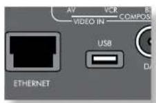
The AVR360 is fitted with a network audio client which is capable of playing internet radio stations as well as stored music on a network storage device such as a PC, or from a USB flash drive.
For information on installing the AVR360 on your network, see page F-17.
The AVR360 supports the following file formats: MP3
WMA (Windows Media Audio)
WAV
FLAC (Free Lossless Audio CODEC)
MPEG-4 AAC (iTunes) with DRM10 support
Favourites
You can store internet radio stations in your 'favourites' folder for easy access later. Once playing, pressing the FAV + key adds the track to the 'favourites' folder. Pressing FAV- removes the station from the 'favourites' folder (this key only has an effect if the station is in the 'favourites' folder).
NOTE
For playback from a network device, the network device needs to running a universal plug and play (uPNp) service, such as Windows Media Player 11. This can be downloaded free of charge from www.milcrosoft.com or installed via the Windows update installer, Windows 7 and Vista have this functionality built in. Windows Media Player requires music library sharing/screening to be enabled in order to serve music to the AVR360. Other free and paid-for uPNp services are available for other computer operating systems. Some network attached storage (NAS) systems include a built-in version of a uPNp service.
Selecting the playback source
Selecting the network client will allow playback of internet radio stations and stored music on a networked storage device or USB memory device.
To select the network source the CR102 remote must first be in AMP device mode (press(a)”), then press(b)”.
- on the remote to select the Network source. You can also cycle to it using the -INPUT / INPUT+ keys on the front panel.
The 'home' page has options for playing audio from a USB device, Internet Radio or from your home network using the 'Music Player' option. Navigate through these items using the and keys. Folders that may contain playable files have a symbol, playable files have a symbol. Once you reach the track you wish to play, press OK key.
Once playing, pressing will pause the track (except Internet Radio).
Pressing the key skips forward one track. If the last track is reached the key is ignored.
Pressing the key skips back one track. If the first track is reached, the key is ignored.
Pressing the 43 key on the remote plays the tracks in the current folder in a random order.
Pressing the key on the remote repeats all the files in the current folder. Pressing it again cancels the repeat function.
USB playback
Insert a USB device into the socket on the AVR360 and select the network client input. The USB device appears in the list of folders that can be navigated. Highlight it using the and keys and press to navigate the contents of the USB device. Navigate through folders (using the , and keys) to a music file and press the OK key to play the file.
Internet radio stations
Although you can manually browse for an internet radio station, the AVR360 uses the vTuner service to allow easy selection of favourite internet radio stations and podcasts. To set up this service for your AVR360, please visit www.arcamradio.co.uk
There, you will be asked to enter the Media Access Controller (MAC) address which is the unique ID of your AVR360. This MAC address can be found in the network section of the setup menu.
Once you have entered the MAC address, you can then browse stations and podcasts and set up groups of favourite stations. When you next connect your AVR360 to the internet, these groups will appear in the 'My favourites' folder.
Pressing the INFO key will cycle what is shown on the lower portion of the front panel display between:
Flapsed Time (default)
■ Processing mode
Album (if available)
■ Artist (if available)
File information (bitrate, type).
iPod
It is possible to connect an iPod to your AVR360 using either the Arcam drDock or irDock accessories (please contact your dealer).
Connect the 9-way plug into the socket marked 'irDock' and the audio leads to the VCR input (the iPod input can be changed in the General Setup menu). If your iPod has video output and you are using the irDock, connect the composite and S-Video leads to the VCR video inputs.
To select the iPod input, press the key on the remote while inAMP Device Mode, or cycle to it using the -INPUT/ INPUT + keys on the front
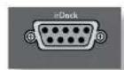
panel. Find songs to play by navigating through Artists, Albums etc. using the , and keys.
The AVR360 allows independent routing and control of analogue audio and Composite video to a separate set of equipment, typically used for a second living space, e.g., bedroom or lounge.
The connection guide on the following page shows how the AVR360 is normally connected in a multi-room installation.
Zone 2
Zone 2 receives only signals obtained by the AVR360 from the analogue audio and Composite video inputs. The analogue inputs are required because there is no analogue-to-digital, digital-to-analogue or DSP processing available for Zone 2 signals - the AVR360 only converts video formats for Zone 1.
For this reason, we recommend that in addition to any digital connections, the analogue audio and Composite video outputs from your source devices are connected to the AVR360.
Video outputs
The 22 Composite video output connectors of the AVR360 should be connected to the analogue video inputs (usually labelledVIDEO IN or COMPOSITEVIDEO IN) of the display device in Zone 2.
Audio outputs
The Z2 OUT, R and L phonon sockets should be connected to the analogue audio inputs (Usually labelled ANALOGUE AUDIO IN) of the Zone 2 display device, or to the inputs of an additional stereo power amplifier in Zone 2 (for example, the Arcam P38).
Speaker outputs
If the main zone has a 5.1-channel surround sound speaker system (not a 7.1-channel system), the spare SBL and SBR speaker outputs can be used to power speakers in Zone 2, so that a power amplifier is not required. To configure the outputs, navigate to the "Spkr Types" option in the Setup Menu and set the option "Use Channels 612 for" to "Zone 2" (see page b-32).
Zone 2 control connections
The AVR360 also allows remote control from Zone 2.
Z2IR
This allows the AVR360 to be controlled remotely from Zone 2 via Intra-red remote control. Connect a remote IR receiver in Zone 2 to allow control of the AVR360 from this listening/ viewing area.
For more information on remote IR receivers, see 'Z1 IR' on page 17.
TRIG2
This allows the AVR360 to remotely switch on devices in Zone 2 when Zone 2 is selected. For example you could set your television in Zone 2 to switch on when Zone 2 is selected on AVR360.
For more information on triggers, see 'Trigger connectors' on page F-17. Please note that not all AV devices have this feature, nor are triggers essential for listening and viewing in a separate zone.
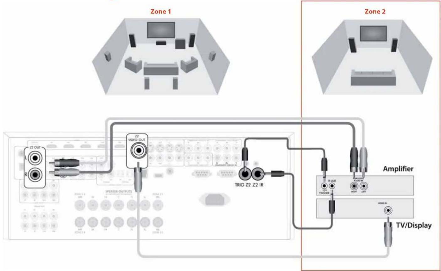
Multi-room connection guide

Code Learning
The CR102 comes with a complete library of preprogrammed codes. After you have set up the CR102 for your device, you may find that there are one or more functions on your original remote which do not have a place on the CR102 keyboard. For convenience, the CR102 offers a Code Learning feature that allows you to copy up to 16 functions from an original remote control onto the CR102 keyboard.
Before you start, make sure that:
The original remote control is working correctly.
The remotes are not pointing at your device.
The remotes have new batteries.
The remotes are not in direct sunlight or under strong fluorescent lights.
Learned functions are mode-dependent: You could theoretically assign up to eight different functions to a single key (the CR102 can handle a total of 16 learned functions).
Example: To copy the 'text hold' function from a TV remote onto the key of your CR102
- Place both remotes on a flat surface, 2 to 5cm apart, with the IR ports facing each other.
- On the CR102, press and hold until the power LED blinks twice:
- Press ⑨⑦⑤ 'The power LED blinks twice:
- On the CR102, press the device key that matches the 'source' device (e.g. if you're learning a TV function, press).
- On the CR102, press the key to which you want to assign the learned function (e.g. 1). The device key blinks rapidly.
- On the original remote, press and hold the function key that you want to learn (e.g., TEXT HID) until the CR102 device key blinks (wice: 串
- If you want to learn other functions from the same source device, simply repeat steps 5 and 6 pressing the next key you want to learn.
-
To exit Code Learning mode, press and hold until the device key blinks twice
-
To use the learned function on the CR102, press the Device Mode key, followed by the function key.
In this example, you'd press
followed by
Shifted Learning
You can assign a learned function to a CR102 key without sacrificing its original function.
You can assign Shilled Learning functions to an except for: Device Mode keys (e.g. ^ ), or n keys (1) to (9).
-
To assign a Shifted Learning function, simply follow Code Learning steps in the previous section. During step 5, press shift once before you press the key to which you want to assign the learned function.
-
To access the shifted function, press and then the target key.
Important notes
Once you start a Code Learning session, you have approximately 10 seconds to conduct each step. Any longer, and a timeout means that you'll have to start the process again.
The Learning feature is mode-specific - you can copy one feature per mode onto a key.
The CR102 can learn approximately 16 functions in total.
To replace a learned function, simply assign a new one to the same key.
- Learned functions are retained when you change batteries.
If Code Learning fails, try altering the distance between the two remotes; make sure that the light in the area is not too bright.
To delete a learned function
- Press and hold until the power LED blinks twice:
- Press⑨⑦⑥. The power LED blinks twice:
- Press a Device Mode key once. For example, if you want to delete one of your learned TV functions, press (w).
- Press twice on the key you want to deassign. The handsect blinks twice: to confirm.
The original function of the CR102 is restored.
To delete a Shifted Learned function:
To delete a Shifted Learned function, pres (^(1)) before you press the key to be deassigned (during step 4 above).
To delete ALL learned functions within a given Device Mode
-
Press and hold until the power LED blinks twice:
-
Press (9)7(6) - the power LED blinks twice:
- Press the appropriate Device Mode key twice.
Creating Macros
You can program your CR102 to issue a sequence of commands when you press a single key. Any sequence of commands you regularly use can be reduced to a single key press for your convenience.
For example, you might want to turn off your TV, VCR and Satellite at the same time.
A key programmed with a Macro is available in all modes; it will replace that key's different functions for all modes.
A Macro can consist of up to eight key presses.
Example: To assign a Macro to the key
- Press and hold until the power LED blinks twice:
- Press⑨⑨⑤
- Press (the Macro will be assigned to this key).
- Press (空) (空) (空) (空) (These are the Macro steps you wish to record.)
- To store the Macro, press and hold until the power LED blinks twice:
Now, whenever you press the CR102 will toggle the power to your TV, VCR and Satellite.
The important word here is 'toggle'. For example, if the TV and Satellite devices are currently on, but the VCR is off, pressing will switch off the TV and Satellite and switch on the VCR (rather than switching all three devices on or off).
When using Macros, remember that you may need to change mode or use (a), and that each key press (including changing modes and pressing) counts as one of the Macro steps. You cannot use a Macro key within another Macro.
If the amount of memory storage for a particular Macro is exceeded, the power LiD comes on for five seconds. You can, however, save the macro steps up to that point by pressing or you can cancel the Macro recording by pressing any other key.
The delay between key presses is recorded as part of the Macro. A delay of up to 30 seconds is permitted.
Example: To deassign the Macro associated with the key
- Press and hold until the power LED blinks twice:
- Press⑨⑨⑤
- Press
- Press and hold until the power LED blinks twice:
Volume punch-through
Volume punch through means that, no matter which Device Mode is selected, the CR102 controls the AVR360 volume. You don't need to press on your CR102; this feature is switched on by default.
There are times, however, when you might want to control a device's volume directly when in a specific Device Mode.
Example: To cancel volume punch-through for a TV (AV mode)
- Press once.
- Press and hold until the power LED blinks twice:
- Press(9)⑨③.
- Press. The power LED blinks four times.
Now, while in TV (AV) mode, you will be able to control the volume or mute functions of your TV directly.
To completely cancel all volume punchthrough settings
- Press and hold until the power LED blinks twice:
- Press⑨⑨③
- Press. The power LED blinks four times
Now, whichever mode you're in, you will have direct access to that device's volume or mute functions, assuming they are available. You would need to switch to AMP mode to alter the AVR360 volume.
Example: To restore default volume punchthrough settings to all Device Modes
- Press and hold until the power I.F.D. blinks twice:
- Press⑨⑨③
- Press, The power key LED blinks twice:
Key Mover
Sometimes you might find that a key you use a lot for your system is in the 'wrong' place on the CR102 keypad for your comfort. It's quite easy to reassign a favourite function to a more accessible key. It is even possible to move a function from one Device Mode to another Device Mode.
Example: To assign the function to the key in SAT mode
- Press
- Press and hold until the power LED blinks twice:
- Press⑨⑨④
- Press the key you want to move (e.g.,)
- Press the key you want to move the key to (e.g.,).
Now, pressing either or while in SAT Device Mode makes the CR102 transmit the function.
To completely swap over the functionality of the two keys to put the functionality on the key, repeat the above process again, but swap over the key and key presses in the example.
Note that the function that is copied over to the new key is always the original function of the old key.
Restore a moved key
To restore a key to its previous function, repeat the example above, pressing the key to be restored twice (copy it back to itself).
Restore all moved keys for a Device Mode
To restore all keys in a Device Mode to their original functional positions, repeat the example above, but press the relevant Device Mode key (e.g. 空 ) at points 1, 4 and 5 in the example.
Copy a key between Device Modes
It is possible to copy functions between Device Modes. However, remember that button functions are Device Mode specific and therefore effectively 'punch-through' to the original Device Mode when copied over.
The following example copies the AVR360DIRECT function from the CR102 AMP device mode to the shifted function of the button on AV Device Mode.
- Press and hold until the power LED blinks twice:
- Press(9)4
- Press the Device Mode key of the function you want to move (e.g. ).
- Press the function key you want to move (e.g., DIRECT)
- Press the key of the Device Mode you want to copy the function to (e.g. u x )
- Press the button graphic
- Press the key you want to copy the function to (e.g.
If you prefer to copy the key to the main function of the button instead of the 'shifted' function, omit point 6 in the above example.
Mode Mover
If your home entertainment setup contains devices of the same type (e.g., two TVs, perhaps from different manufacturers) you can still control both those devices with the CR102. You simply need to reassign an unused Device Mode key.
NOTE
Before using Mode Mover, make sure both the source and destination Device Mode keys are unlocked (see next section).
Example: To use the key to control a second TV
- Press and hold until the power LED blinks twice:
- Press⑨⑨②
- Press the Device Mode key for the type of device you want to control (e.g., for a TV, press).
- Press the Device Mode key you want to use (e.g., ).
- Don't forget to set up the CR102 to control the second device, using one of the methods on page 12-25. Note that volume punch-through is not applied to a Device Mode that has been copied using Mode Mover. However, AVR360 volume punch-through functionality can be restored when you have used Mode Mover, by copying () and from the AMP Device Mode to the same physical buttons on the new moved Device Mode using the last example shown in Key Mover.
To restore a moved Device Mode key to its original state
- Press and hold until the power LED blinks twice:
- Press⑨⑨②
- Press the Device Mode key you want to restore twice.
Locking/Unlocking a specific Device Mode
When you first unpack your CR102 and insert the batteries, for your convenience it is able to control certain Arcam components automatically (e.g. BD players, Amplifiers, Tuners and CD Players). We achieve this by preprogramming specific Arcam device codes onto the relevant Device Mode keys, then locking the Device Modes so you don't reprogram them inadvertently.
If you want to override these locked default settings - to control a third-party DVD player, for example - you will first need to unlock DVD Mode before setting up the CR102 using one of the methods described at the start of this guide.
Here are the factory default settings:
| Device Mode Default status Default Arcam | |
| codes | |
| DVD | Locked 0762 |
| SAT | Unlocked 1205 |
| AV | Unlocked 0586 |
| TUN | Locked 2009 |
| AMP | Locked 1242 |
| PVR | Unlocked 1930 |
| VCR | Unlocked 0111 |
| CD | Locked 2010 |
Alternative codes are available for multi-room solutions, or in the case of code clashes with other manufacturer's products.
For example:
DVD (system code: 2) 1655
AMP (system code: 19) 1954
You will need to change the system code on the product you wish to control, as well as the CR102.
NOTE
The AMP Device Mode can only be used to control Arcam amplifiers like the AVR360, either on its default or alternative IR system codes.
To toggle a Device Mode lock setting:
1. Press the Device Mode key you want to unlock (e.g.
2. Press and hold until the power LED blinks twice:
3.Press9B2
The power LLD blinks (wice when being locked, and blinks four times when being unlocked.
If you enter an invalid key sequence, the power LED gives one long blink and returns to normal operation.
While the Device Mode key is locked, the Direct Code Setup and Move Mode functions are not available.
Mode key IR punch-through
The Mode key IR punch through default is 'on'.
Example: To set the Mode key IR punchthrough to AMP
- Press and hold until the power LED blinks twice:
- Press⑨⑦① The power LED blinks twice:
- Press to punch through IR from it.
Now, whenever you press and release a Mode key, the TR data assigned to AMP is transmitted, no matter what the current mode is (i.e. it 'punches through' any other device).
To cancel Mode key IR punch-through
-
Press and hold until the power I.FD blinks twice:
-
Press ⑨ ⑦ ① The power LED blinks twice:
- Press until the power LED blinks twice
Resetting the CR102
Resetting the CR102 will erase all learned functions across all modes, as well as some other programmed functions like Macros. It will not reset the Device Mode keys; these will remain programmed to your choice of component.
- Press and hold until the power LED blinks twice:
- Press⑨⑧⑩. The power LED blinks four times:
- Press and hold until the power LED blinks twice:
- Press⑨⑨③
- Press The power key LED blinks twice
- Press and hold until the power LED blinks twice:
- Press ⑨ ⑦ ① The power LLD blinks twice:
- Press The power key 1.FD blinks twice:
Command summary
Direct code setup
(e.g. AV mode, NNNN=code number)
NNNN
Library search
(c.g. AV mode)
unl unit turns off
to save
Code blink back
()(9)(0)
(1) count blinks for first N
② count blinks for second N
③ count blinks for third N
count blinks for fourth N
Code learning
(e.g. AV mode fast forward key)
w ⑨⑤ w (many rapid blinks)
(Press key on original remote that you wish to copy)
Delete a learned function
Delete all learned functions with a device
(e.g. AV mode)
9⑦⑤④
Creating macros
(e.g. SRCH key)
995 电电电电电电
Deassign macro
995
Key mover
(e.g. SAT mode, DISP key to MENU key)
99410
Mode mover
(c.g. change SAT to TV(AV))
9⑨②
Restore device mode
(e.g. restore SAT)
992
Locking/unlocking a mode
(c.g.DVD modc)
(i.e. [wo blinks (or lock)
000000000000000000000000000000000000000
(i.e. four blinks for unlock)
Cancel all volume punch-through
中 9⑨③+
Restore volume punch-through
Mode key IR punch-through
97①
Cancel mode key IR punch-through
NOTE
As elsewhere in this Landbook, a single 'blink' of the red LED behind the power button is indicated by the symbol.
Device codes
The tables that begin on page 56 (in the final section of this Handbook) list the four-figure codes for different manufacturers' devices.
Use these when setting your CR102 up to control your devices, as described in Method 1 (see page E-25).
If more than one code number is listed, try the first number. If the results are unsatisfactory, continue trying the numbers for that manufacturer to get the best fit with the functionality required.
If the manufacturer of your equipment is not listed, you can try Method 2, the Library Search (see page F-25). This allows you to scan through every set of codes contained in the CR102's memory.
trouble-shooting
| Problem Check that... | |
| There are no lights on the unit | the power cord is plugged into the AVR360 and the mains socket it is plugged into is switched on. the power button is pressed in.If a red LED is present, the AVR360 is in standby mode. Press any button on the front panel or remote control. |
| The unit responds erratically or not at all to the remote control | there are fresh batteries in the remote control. the front panel window is visible and you are pointing the remote control towards it. |
| The front panel display is blank | the display hasn't been turned off. Press the DISPLAY button on the front panel or remote control. |
| No picture is being produced | your viewing device is turned on and switched to display your AVR360. Test by pressing the MENU button on the AVR360 or on the remote and look for the main menu screen on your display device. the correct video input is selected on the AVR360. the "Video Source" has been set correctly in the "Input Config." menu the video source is on, is operating normally, and is in 'play' mode if appropriate. you have the AVR360 in a video resolution that is compatible with the connection you are using and with your display device. For example, composite video is only capable of carrying 480i and 576i resolutions. Test this by pressing and holding the OK key for more than two seconds to force 480i / 576i output resolutions. |
| There are bright edges or 'ghosts' on the picture | the cables used for analogue video connections are designed to carry video (i.e., they are 75Ω coaxial cables). ensure the 'sharpness' control on your display device is switched off or set to near minimum. for HDMI connections, try using a shorter cable or alternatively a different brand. |
| No sound is produced | the correct input has been selected. the "Audio Source" has been set correctly in the "Input Config." menu the source equipment is on, is operating normally and is in 'play' mode if appropriate. the volume is turned up to a reasonable level and the AVR360 is not in mute mode. |
| The sound is poor or distorted | you have not excessively increased the input sensitivity (i.e. reduced the maximum input signal voltage) in the Input Config. menu if an analogue input is being used. you have selected the correct size of speakers to suit your system in the setup menu. |
| Sound only comes from some of the speakers | you have an appropriate surround source selected and playing. the BD/DVD disc is encoded in the appropriate format, and the correct format has been selected in the disc start menu of the BD player (if applicable). the BD/DVD player has been set to output 'bitsstream' audio on the digital output. the display window indicates that the disc you are playing is a multichannel recording (you may need to press the INFO key several times until you get to the 'incoming format' display). all the speakers are correctly connected to the speaker terminals and are secure. you have not selected 'Stereo' as the decoding mode. your speaker balance is correct. you have configured the AVR360 to include all the speakers in your system. |
| Unable to select Dolby Digital or DTS decoding modes | The AVR360 can only apply Dolby Digital and DTS decoding to sources which have been encoded in the same format. Check that: digital source is selected and connected. the source is playing appropriately encoded material. the BD/DVD disc is encoded in the appropriate format and that the correct format has been selected in the disc start menu of the BD player (if applicable). the BD/DVD player has been set to output 'bitsstream' audio on the digital output. |
| When playing a Dolby Digital BD, the AVR360 selects Dolby Pro Logic | you have a digital connection from your BD player. sometimes Dolby Digital BD/DVD discs contain material at either the beginning or the end of the main movie that is not in full 5.1 format, but in two-channel or Pro Logic decoding. |
| Hum on the analogue input | all cables are making a good connection. If necessary withdraw the cable from the connector and plug it fully in again (turn the power off before doing this). the connections inside the source cable connector are not broken or badly soldered. if the hum originates only when one particular source component is connected, that an aerial cable, or disk connection to this source is ground isolated. Contact your installation contractor. |
| There is radio or television reception interference | where the interference is coming from. Switch off each source component in turn, then any other equipment. Most electronic equipment does generate low levels of interference. try re-arranging cabling from the nuisance source away from other cabling. ensure that the cabling used is high quality, specified for its purpose, and is properly screened. if the problem persists, contact your dealer. |
| Problem Check that... | |
| The source switching changes randomly or freezes on one source | ■ there are no static or impulse interference problems caused by nearby power equipment switching, e.g., heating or air conditioning control. Switch the AVR360 off, wait (ten seconds, then switch it on again to clear an operating problem. Contact your installer if the problem returns or persists.■ there is no direct sunlight shining on the infra red detector behind the front panel display. |
| Volume is always too loud when I turn on | ■ the 'max on volume' setting is not set too high. |
| When Zone 2 is put into standby, the main zone is also switched off | ■ the 'zone standby' setting in the setup menu is set to LOCAL. |
| When a USB memory device is connected, 'USB' is not shown in the network client's list of folders | ■ a USB memory device is connected that conforms to the mass storage class.■ a USB hub is not being used. |
| If files on a USB memory device cannot be played: | ■ the USB device is formatted in FAT16 or FAT32.■ the USB device does not have multiple partitions.■ the files are in a compatible format. |
| If files on a computer cannot be played | ■ the files are in a compatible format.■ the computer is connected via a network and not USB - the AVR360 USB port cannot be used for a direct connection to a computer |
| If you cannot connect to a wired network | ■ the Ethernet cable you are using is correctly connected between the AVR360 and the network hardware.■ the network is set up for fixed IP addressing and you have the AVR360 set to use DHCP.■ the network is set up for DHCP and you have the AVR360 set to use fixed IP addressing. |
| If you cannot connect to a favourite internet radio station | ■ the station is still broadcasting or is not congested - try again later. |
| If the internet radio station sound quality is poor or broken | ■ the radio station does not have a low bit rate (use the INFO key to find this or look on the OSD).■ the network is not slow or congested. |

| Continuous power output, pc channel, 8Ω | |
| 2 channels driven, 1kHz, 0.2% THD 90W | |
| 2 channels driven, 20Hz-20kHz, <0.02% THD 80W | |
| 5 channels driven, 1kHz, 0.2% THD 75W | |
| Residual noise & hum <0.3mV | |
| Inputs | |
| Line inputs: | |
| Nominal sensitivity 1V, 2V, 4V (user adjustable) | |
| Input impedance 47k | Ω |
| Signal/noise ratio (CCIR, 65W) 100dB | |
| Preamplifier outputs | |
| Nominal output level 1V RMS | |
| Output impedance 560 | Ω |
| THD+1N (20Hz-20kHz) 100dB | |
| Video inputs | |
| Component video signal/noise 83dB | |
| Composite video signal/noise 70dB | |
| Headphone output | |
| Maximum output level into 332 2Vrms | |
| Output impedance <5 | Ω |
| General | |
| Mains voltage | 220 - 240V, 50Hz |
| Power consumption (maximum) | 1kW (Thermal dissipation approx. 3400 BTU/hour) |
| Power consumption (idle, typical) | 100W (Thermal dissipation approx. 340 BTU/hour) |
| Power consumption (standby) | <0.5W |
| Dimensions | 433 x 425 x 171mm |
| W x D (including speaker terminals) x H (including fct) | |
| Weight (net) | 15.5kg |
| Weight (packed) | 20kg |
| Supplied accessories | Mains lead CR102 remote control 4 x AAA batteries Handbook DAB aerial PM aerial AM loop aerial Calibration microphone |
| E&OE | |
| NOTE: All specification values are typical unless otherwise stated. | |
Continual improvement policy
Arcam has a policy of continual improvement for its products. This means that designs and specifications are subject to change without notice.

Worldwide Guarantee
This entitles you to have the unit repaired free of charge, during the first two years after purchase, provided that it was originally purchased from an authorised Arcam dealer. The Arcam dealer is responsible for all after-sales service. The manufacturer can take no responsibility for defects arising from accident, misuse, abuse, wear and tear, neglect or through unauthorised adjustment and/or repair, neither can they accept responsibility for damage or loss occurring during transit to or from the person claiming under the guarantee.
The warranty covers:
Parts and labour costs for two years from the purchase date. After two years you must pay for both parts and labour costs. The warranty does not cover transportation costs at any time.
Claims under guarantee
This equipment should be packed in the original packing and returned to the dealer from whom it was purchased. It should be sent carriage prepaid by a reputable carrier - not by post. No responsibility can be accepted for the unit whilst in transit to the dealer or distributor and customers are therefore advised to insure the unit against loss or damage whilst in transit.
For further details contact Arcam at:
Arcam Customer Support Department,
Pembroke Avenue, Waterbeach, CAMBRIDGE, CB25 9QR, England
or via www.arcam.co.uk.
Problems?
If your Arcam dealer is unable to answer any query regarding this or any other Arcam product please contact Arcam Customer Support at the above address and we will do our best to help you.
On-line registration
You can register your product on-line at www.arcam.co.uk.

ARCAM
AVR360
MANUEL Amplificateur surround AVR
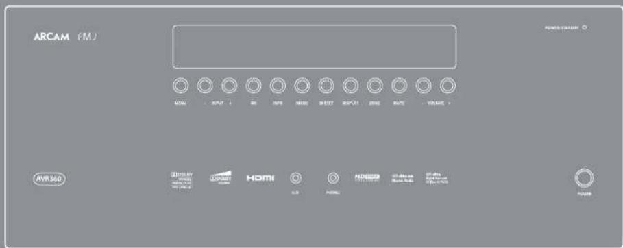


CAUTION
BSS OF ELECTRIC SHOCK STOP
ATTENTION
RISQUE DE CHOICE ELECTrique

inFoRmations FCC (PouR les Clients
ameRicains)
1.PRoDuit
AV, SAT, BD, VCR, PVR
VCR, PVR, BD, CD, AV, SAT
AV, SAT, BD, VCR, PVR, CD
m = 311 ;


Use Channels 6+7 for
PLII Dimension PLII Centre Lar
PLI Panorama
For more information on triggers, see 'Trigger connectors' on page F-17. Please note that not all AV devices have this feature, nor are triggers essential for listening and viewing in a separate zone.
Arcam Customer Support Department,
Pembroke Avenue, Waterbeach, CAMBRIDGE, CB23 9QR, Royaume Uni ou sur le site www. arcam.co.uk.
Des problèmes?
AV, SAT, BD, VCR, PVR
VCR, PVR, BD, CD, AV, SAT
AV, SAT, BD, VCR, PVR, CD
Der AVR360 Receiver Receive Mask and Films due her Performance lebending werden.
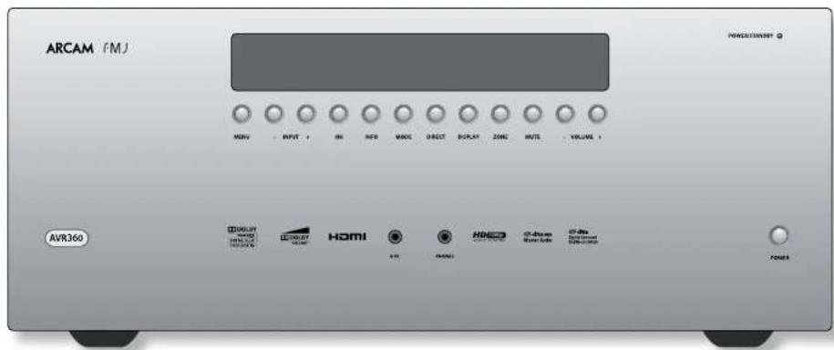
Component/RGB-Anschlüsse
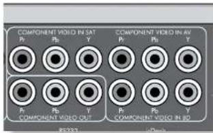
Digitale Audioanschlüsse
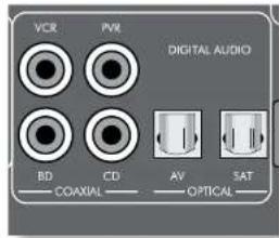
VCR, PVR, BD, CD, AV, SAT
AV, SAT, BD, VCR, PVR, CD
Zone 2 Fixed Vol - The Zone 2 volume control can be locked at the current value for use with an external amplifier with its own volume control in Zone 2.
MPEG-4 AAC (iTunes) with DRM10 support
Favoriten
Arcam Customer Support Department
Pembroke Avenue,
Waterbeach,
CAMBRIDGE
CB259QR
England.
HANDLEIDING AVR surroundversterker


CAUTION
RISK OF ELECTRIC SUSTAIN FOR ENDORIN
ATTENTION
RISQUE DE CHOC ELECTRATURE: PR.245 CHINBER

WAARSCHUWINGEN VOOR INSTALLATIE
Apparaatcodetabellen 56
AV, SAT, BD, VCR, PVR
Component/RGB videoconnectors

VCR, PVR, BD, CD, AV, SAT
AV, SAT, BD, VCR, PVR, CD
Slui de linker - en rechiringan op de linker - en rechirugting van uwBronparapparu.
DIGITAL AUDIO OUT (digital audio unit), any until end of de
analoge coak-uitgangen woor de inker en techter kanaien.
Gebruik in eik affondcrink geval, de airdio-ingangen,
Sockets referring to "7.2" relate to connections used in multi-room installation. For more information on these connectors, see pagina NL 46.
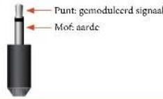
Z1IR
In menu's navigergren
Dolloy Digital EX - Dolloy BLX Mexico
Dolby PLIIx Music
Surround (b.v. Dolby Pro Logic II Movie, Neo6 Music, etc.)
Stereo.
Arcam Customer Support Department,
Pembroke Avenue, Waterbeach, CAMBRIDGE, CB25 9QR, Engeland.
of www.arcam.co.uk.
Problems?
A&R CAMBRIDGE ITD, PEMBROKE AVENUE, WATERBEACH, CAMBRIDGE CB25 9qR, ENGIAND

- HANDBOOK AVR surround amplifier
- Important safety instructions
- FCC inFoRmation (FoR us CustomcRs)
- 1.PRoDuCt
- 2.imPoRrant notice:
- Do not moDiFy His PRoDuCt
- note
- saFety inFoRmation
- (FoReeuRoPean Cus tomeRs)
- a note aBout ReCyClinG:
- CoRRcT DisPosal of tllis PRODuCt
- Contents
- Professional Installation?
- DIY setup?
- Placing the unit
- Power
- Standby power
- Interconnect cables
- Radio interference
- Trademark acknowledgements
- NOTE
- General
- Making connections
- NOTE:
- HDMI connectors
- AV, SAT, BD, VCR, PVR
- OUTPUT
- Component/RGB video connectors
- COMPONENTVIDEO IN SAT,AV,BD
- COMPONENTVIDEOOUT
- Zone 2 connectors
- S-Video and Composite connectors
- AV, VCR, BD, SAT
- Digital audio connectors
- VCR, PVR, BD, CD, AV, SAT
- MCH input
- Analogue pre-amplifier outputs
- Analogue audio inputs
- AV, SAT, BD, VCR, PVR, CD
- Front panel AUX input
- Front panel PHONES socket
- Connection guide
- Blu-ray Disc (BD) / DVD player
- Satellite receiver
- CD player
- Connecting an iPod using the Arcam irDock
- Aerial connectors
- DAB
- FM
- AM
- Connecting an aerial
- Data connectors
- drDock/irDock
- RS232 serial connector
- Network connector
- Ethernet
- USB connector
- Trigger connectors
- TRIGZ1
- TRIGZ2
- Infra-red (IR) connectors
- Z1IR
- Z2IR
- speakers
- Connecting speakers
- Speaker cables
- Bi-Amping the Front Left & Right speakers
- Connecting subwoofoers
- Using external power amplifiers
- FL,FR,C
- SUB
- SR, SL
- SBR, SBL
- Operating your AVR360
- Switching on
- Standby
- To switch on from standby
- Front panel display
- Selecting a source
- Stereo Direct
- Volume control
- Headphones
- Using Zone 2
- Extended front panel menu
- Restore to factory defaults
- Change remote code
- Store secure backup
- -Enter PIN
- -Change PIN
- -EXIT
- Updating firmware via USB
- The CR102 universal remote controller
- Using the remote control
- Inserting batteries into the remote control
- Notes on batteries:
- Useful information
- Backlight
- PowerLEDblinks
- Timeouts and unassigned keys
- Low voltage indicator
- Device Mode / Source keys
- Navigation keys
- The CR102 complies with Part 15 of the FCC rules
- Controlling other devices
- Method 1 (Direct code setup)
- What if I still can't control my device?
- Notes:
- Method 2 (Library search)
- Example: To search for a TV code
- Code blink-back
- Example: To blink back your Television code
- Make a note of the codes
- AMP Device Mode
- 01: Selects the Display input on the AVR360
- 02: (television Audio Return Channel).
- Pod commands
- Network commands
- TUN TUN Device Mode
- DVD DVD/BD Device Mode
- SAT Device Mode
- AV Device Mode
- PVR Device Mode
- VCR Device Mode
- CD Device Mode
- essential setup
- Speaker types
- Crossover frequency
- MCH sub level
- Use Channels 6+7 for
- Speaker Distances
- Speaker Levels
- Problems
- Using a subwoofer
- Entering Setup mode
- Unstable OSD menu or picture display?
- Navigating the setup menu
- ... using the remote control
- ... using the keys on the front panel
- Input Config.
- Treble - Bass -
- General Setup
- Auto Setup
- Spkr Types
- Front Left/Right
- Spkr Distance
- Spkr Levels
- Video Inputs
- Video Outputs
- Important points to remember:
- For the analogue output
- For the HDMI output
- Mode
- For Stereo sources:
- For Multi-channel sources:
- Zone Settings
- Network
- Introduction
- Modes for digital sources
- Modes for analogue sources
- Mode memory
- Two-channel source modes
- Stereo
- Dolby Pro Logic II
- Dolby Pro Logic IIx
- Dolby Pro Logic
- DTS Neo:6
- Multi-channel source modes
- Decoding modes
- Dolby volume
- Settings
- Volume Leveller
- Calibration Offset
- Tuning/Channel Selection
- FM/AM analogue radio
- DAB digital radio
- Internet radio
- Saving and selecting Presets
- Deleting Presets
- Favourites
- Selecting the playback source
- USB playback
- Internet radio stations
- iPod
- Zone 2
- Audio outputs
- Speaker outputs
- Zone 2 control connections
- TRIG2
- Code Learning
- Example: To copy the 'text hold' function from a TV remote onto the key of your CR102
- Shifted Learning
- Important notes
- To delete a learned function
- To delete a Shifted Learned function:
- To delete ALL learned functions within a given Device Mode
- Creating Macros
- Example: To assign a Macro to the key
- Example: To deassign the Macro associated with the key
- Volume punch-through
- Example: To cancel volume punch-through for a TV (AV mode)
- To completely cancel all volume punchthrough settings
- Example: To restore default volume punchthrough settings to all Device Modes
- Key Mover
- Example: To assign the function to the key in SAT mode
- Restore a moved key
- Restore all moved keys for a Device Mode
- Copy a key between Device Modes
- Mode Mover
- Example: To use the key to control a second TV
- To restore a moved Device Mode key to its original state
- Locking/Unlocking a specific Device Mode
- Mode key IR punch-through
- Example: To set the Mode key IR punchthrough to AMP
- To cancel Mode key IR punch-through
- Resetting the CR102
- Command summary
- Direct code setup
- Library search
- Code blink back
- Delete a learned function
- Delete all learned functions with a device
- Deassign macro
- Restore device mode
- Locking/unlocking a mode
- Restore volume punch-through
- Cancel mode key IR punch-through
- Device codes
- trouble-shooting
- Continual improvement policy
- Worldwide Guarantee
- The warranty covers:
- Claims under guarantee
- Problems?
- On-line registration
- ARCAM
- AVR360
- MANUEL Amplificateur surround AVR
- inFoRmations FCC (PouR les Clients
- ameRicains)
- 1.PRoDuit
- m = 311 ;
- PLI Panorama
- Des problèmes?
- Component/RGB-Anschlüsse
- Digitale Audioanschlüsse
- Favoriten
- HANDLEIDING AVR surroundversterker
- WAARSCHUWINGEN VOOR INSTALLATIE
- Component/RGB videoconnectors
Brand : ARCAM
Model : FMJ AVR360
Category : Receiver