
APU70 - Audio System YAMAHA - Free user manual and instructions
Find the device manual for free APU70 YAMAHA in PDF.

| Brand | YAMAHA |
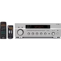
| Model | APU70 |
| Product type | Audio system with integrated amplifier |
| Output power | 20 W + 20 W (20 Hz-20 kHz, 6 Ω, 0.4% THD) |
| Maximum power | 26 W + 26 W (1 kHz, 6 Ω, 10% THD) |
| Input sensitivity | PC, AUX1, AUX2: 2.1 V or more (1 kHz) |
| Frequency response | 20 Hz – 20 kHz (±1.0 dB) |
| Total harmonic distortion | 0.06% or less (4 V/6 Ω) |
| Signal-to-noise ratio | 85 dB or more (USB to speaker output) |
| Power supply | AC 120 V, 60 Hz (USA/Canada) or AC 230 V, 50 Hz (Europe/UK) or AC 240 V, 50 Hz (Australia) |
| Power consumption | 60 W (USA/Canada) or 55 W (Europe/UK/Australia) |
| DSP functions | Near-Field Cinema DSP, 7 sound field programs (HALL, JAZZ, CHURCH, GAME, MOVIE, LIVE, VDD) |
| Virtual 3D | Yes, Yamaha Virtual 3D technology |
| Graphic equalizer | 7 bands, adjustable via software |
| Connectivity | USB, optical/coaxial digital inputs, analog inputs, headphone output |
| Compatible audio formats | PCM, Dolby Digital, DTS, multi-channel audio (2, 4, or 6 channels via USB) |
| Remote control | Yes, included with batteries |
| Maintenance and cleaning | Use a clean, dry cloth. Do not use chemical solvents. |
| Safety | Do not open the cabinet. Observe the indicated voltage. Ensure adequate ventilation (10 cm space around). |
Frequently Asked Questions - APU70 YAMAHA
User questions about APU70 YAMAHA
0 question about this device. Answer the ones you know or ask your own.
Ask a new question about this device
Download the instructions for your Audio System in PDF format for free! Find your manual APU70 - YAMAHA and take your electronic device back in hand. On this page are published all the documents necessary for the use of your device. APU70 by YAMAHA.
USER MANUAL APU70 YAMAHA
- This manual explains how to operate this unit. Refer to the separate "SET UP MANUAL" for how to connect this unit with other equipment, and to install the Application Software, etc. to your computer from the supplied CD-ROM.
- This manual mainly explains how to operate this unit using the front panel of this unit and the supplied remote control.
- When this unit and your computer is connected with the USB cable, and the supplied Application Software is installed on the computer, you can operate this unit from the computer using the Application Software. Refer to the online help of the Application Software for how to use the Application Software.
The Application Software extends the use of this unit with additional functions which cannot be used with the front panel keys or the remote control. This manual introduces those functions by the following style.
Example:

■ Adjusting USB MIX LEVEL
When an input other than the USB terminal is selected, you can listen to the mixed sound signals from the selected input and from the USB terminal. Also, the mixing ratio of the signals from the USB terminal can be adjusted.
* Refer to the online help of the Application Software for details.

This manual also offers brief explanations about the functions available with the Application Software on page 15–18. Refer to the online help of the Application Software for details of how to use the functions.
Features
- This unit brings high-quality audio to your computer.
- The USB interface allows remote control of this unit from your computer, using the supplied Application Software, plus various audio I/O options.
- Ideal for use with computer games, internet music, CD-ROM, DVD, multimedia software, and more.
- Yamaha's Near-Field Cinema DSP (Digital Sound field Processing) technology provides live music performance and movie theater surround sound. The sound effect of DSP is also available for headphone listening.
- Sophisticated Virtual 3D technology reproduces multichannel sources such as Dolby Digital* and DTS** providing a realistic surround effect with just two speakers.
- This unit is compatible with the following audio signals received via a USB connection: multi-channel (two, four and six channels) audio, high quality digital audio of 24 bits/48 kHz and Dolby Digital-encoded signals. (Some operating systems and software programs do not support this feature.)
\* VIATUAL DO DOLBY DIGITAL
Manufactured under license from Dolby Laboratories. "Dolby", "Pro Logic" and the double-D symbol are trademarks of Dolby Laboratories. Confidential Unpublished Works. ©1992–1997 Dolby Laboratories, Inc. All rights reserved.
\*\* dts VIRTUAL 5.1
Manufactured under license from Digital Theater Systems, Inc. US Pat. No. 5,451,942 and other world-wide patents issued and pending. "DTS", "DTS Digital Surround", are trademarks of Digital Theater Systems, Inc. Copyright 1996 Digital Theater Systems, Inc. All Rights Reserved.
CONTENTS
CAUTION.... 2
OUTLINE OF THIS UNIT
Main features of this unit...... 3
Virtual 3D......4
Digital Sound Field Processing
(DSP)......4
CONTROLS AND THEIR FUNCTIONS
Front panel & Remote control..... 5
About the display....7
BASIC OPERATION
Playing a source 8
Using sound field programs ..... 10
Recording.... 11
ADVANCED OPERATION
Adjusting surround effect ...... 13
Setting USB channel 14
Operating this unit with the
Application Software...... 15
APPENDIX
Troubleshooting 19
Specifications 20
CAUTION: Read this before operating this unit
- To assure the finest performance, please read this manual carefully. Keep it in a safe place for future reference.
- Install this unit in a cool, dry, clean place – away from windows, heat sources, sources of excessive vibration, dust, moisture and cold. Avoid sources of humming (transformers, motors). To prevent fire or electric shock, do not expose the unit to rain or water.
- Never open the cabinet. If something drops into the set, contact your dealer.
- Do not use force on switches, controls or connection wires. When moving the unit, first disconnect the power plug and the wires connected to other equipment. Never pull the wires themselves.
- The openings on the unit cover assure proper ventilation of the unit. If these openings are obstructed, the temperature inside the unit will rise rapidly; therefore, avoid placing objects against these openings. To prevent fire or damage, install the unit in a well-ventilated area.
To prevent fire or damage, be sure to allow a space of at least 10 cm behind, 10 cm on both sides and 10 cm above the top panel of the unit. - The voltage used must be the same as that specified on this unit. Using this unit with a higher voltage than specified is dangerous and may result in fire or other accidents. YAMAHA will not be held responsible for any damage resulting from use of this unit with a voltage other than that specified.
- Always set the volume to minimum before starting audio playback. Increase the volume gradually to an appropriate level after playback has been started.
- Do not attempt to clean the unit with chemical solvents as this might damage the finish. Use a clean, dry cloth.
- Be sure to read the "TROUBLESHOOTING" section regarding common operating errors before concluding that the unit is faulty.
- When not planning to use this unit for a long period (i.e., vacation, etc.), disconnect the AC power plug from the wall outlet.
- To prevent lightning damage, disconnect the AC power plug when there is an electric storm.
- Grounding or polarization – Precautions should be taken so that the grounding or polarization of appliances is not defeated.
For U.K. customers
If the socket outlets in the home are not suitable for the plug supplied with this appliance, it should be cut off and an appropriate 3 pin plug fitted. For details, refer to the instructions described below.
Note: The plug severed from the mains lead must be destroyed, as a plug with bared flexible cord is hazardous if engaged in a live socket outlet.
SPECIAL INSTRUCTIONS FOR U.K. MODEL
IMPORTANT:
THE WIRES IN MAINS LEAD ARE COLOURED IN ACCORDANCE WITH THE FOLLOWING CODE:
Blue: NEUTRAL
Brown: LIVE
As the colours of the wires in the mains lead of this apparatus may not correspond with the coloured markings identifying the terminals in your plug, proceed as follows: The wire which is coloured BLUE must be connected to the terminal which is marked with the letter N or coloured BLACK. The wire which is coloured BROWN must be connected to the terminal which is marked with the letter L or coloured RED. Making sure that neither core is connected to the earth terminal of the three pin plug.
For Canadian Customers
To prevent electric shock, match wide blade of plug to wide slot and fully insert.
This Class B digital apparatus complies with Canadian ICES-003.
When this unit is turned off by pressing the power switch on the front panel or the POWER key on the remote control, this unit turns into the standby mode. In this mode, this unit is designed to consume a small amount of power. This unit's power supply is completely cut off from the AC line only when the AC power cord is disconnected.
Main features of this unit
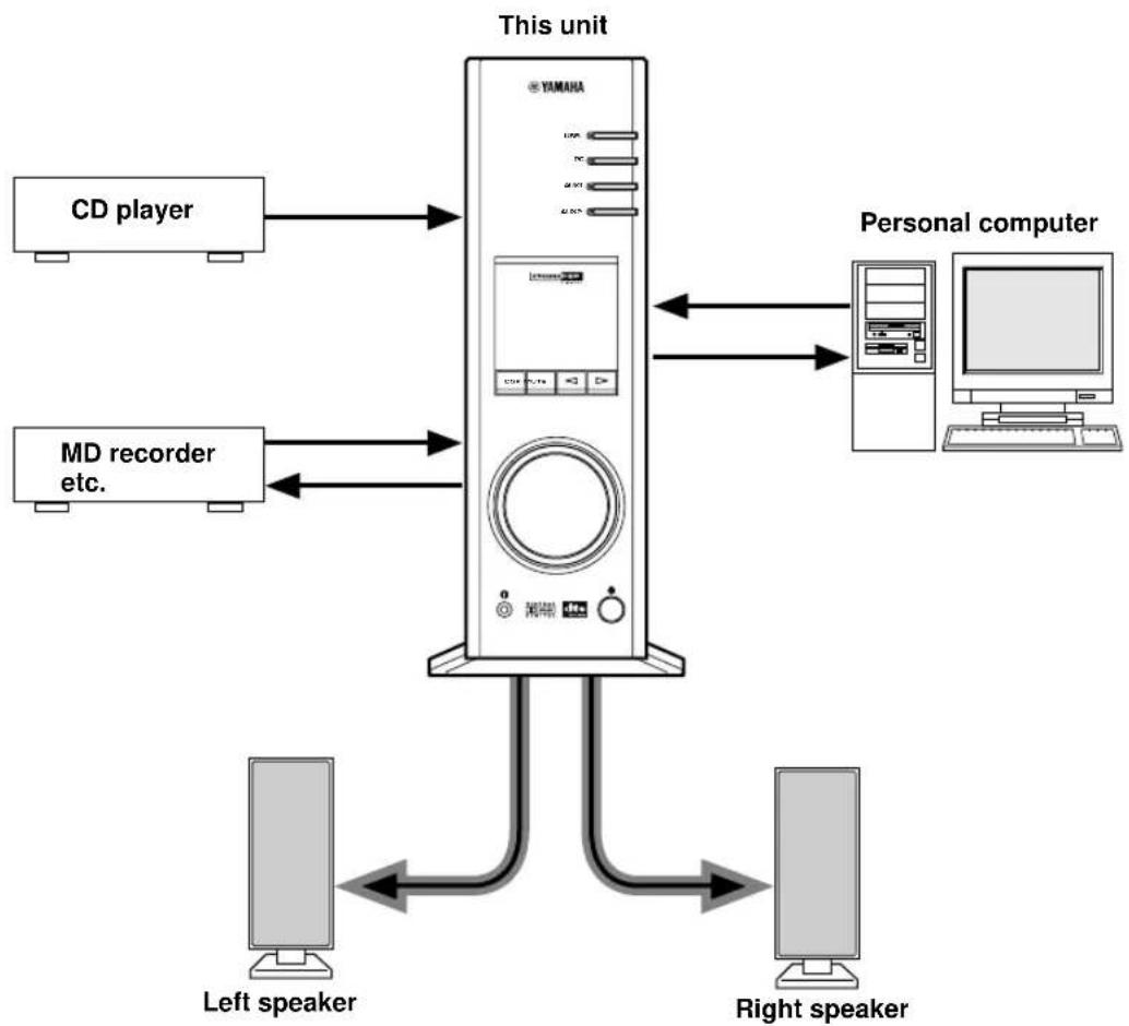
Using Yamaha's unique DSP technology, this unit can bring excitement and realism to any audio source by simulating the acoustic environments of concert halls, movie theaters, and so on with only two speakers. With its stylish, vertical design, this unit allows you to use various audio sources, including your computer, CD player, MD or tape deck, as shown below.
Although this unit can be used as part of a typical hi-fi system, connecting it to your computer via the USB terminal, and running the supplied Application Software, allows you to remotely control this unit from your computer and edit the sound field programs.


flowchart
graph TD
    A["CD player"] --> B["This unit"]
    C["MD recorder etc."] --> B
    D["Personal computer"] --> B
    B --> E["Left speaker"]
    B --> F["Right speaker"]
    E <--> F
[For DP-U50 only]
This unit cannot be connected with speakers directly. Connect this unit to speakers with a built-in amplifier, a mini-component system, etc., or connect this unit to speakers via a power amplifier.
* Refer to the separate "SET UP MANUAL" for connections.
Virtual 3D
Surround sound typically requires several speakers situated in front of and behind the listening position, which requires a substantial amount of space that may not always be available. This unit uses Yamaha's unique "Virtual 3D (three-dimensional)" technology to simulate a typical surround sound system using only two speakers. Virtual
3D, which is used by this unit's sound field programs, simulates the surround effect provided by rear and center speakers, creating "virtual" surround speakers, as shown, so even with only two front speakers, you can still enjoy surround sound.

Digital Sound Field Processing (DSP)
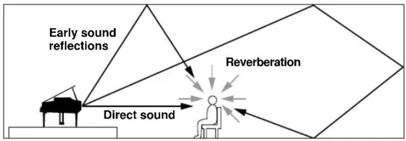
When you listen to a performance in a concert hall, jazz club, or other live music venue, you not only hear the direct sound coming from the musical instruments and singers, but also the “early reflections” and natural reverberation. Early reflections are the initial sound waves that bounce off the floor, ceiling, and walls. Natural reverberation is made up of sound waves that gradually attenuate as they bounce repeatedly off multiple surfaces.
Since the way you hear early reflections and reverberation depends on the shape and size of the building as well as the material and construction of the walls and ceiling, each venue has its own unique “sound,” called its “sound field.” At Yamaha, we have measured all the elements that make up a typical sound field—direction and level of the reflections, band-width characteristics, and delay times—at famous concert halls and opera houses around the world. The information gained in this process has been converted into programs that can be reproduced using Yamaha’s DSP technology. Using its on-board DSP, this unit can process any audio source and recreate the atmosphere of the original venue.
flowchart
graph TD
    A["Early sound reflections"] --> B["Reverberation"]
    C["Direct sound"] --> B
    B --> D["End"]
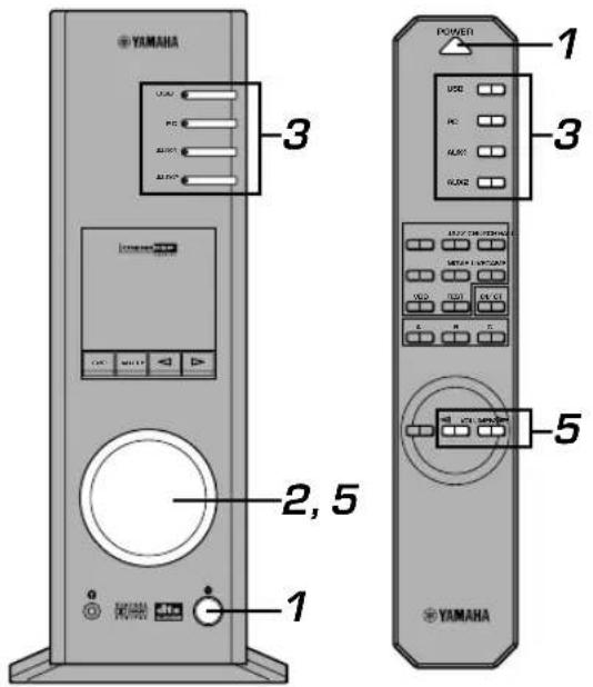
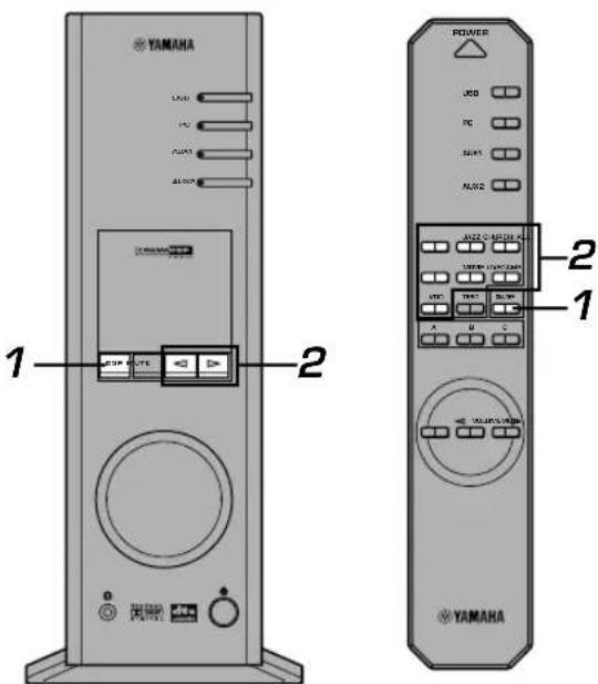
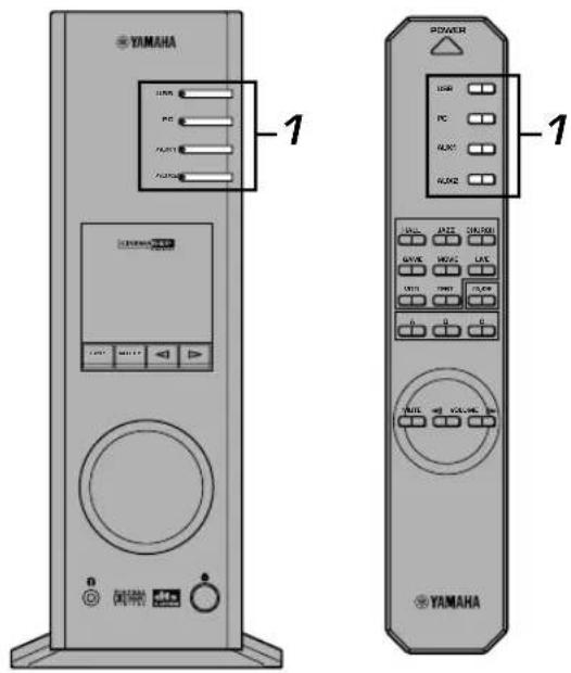
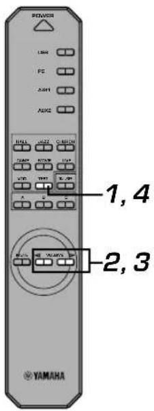
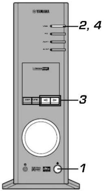
Front panel & Remote control
Front panel
Remote control
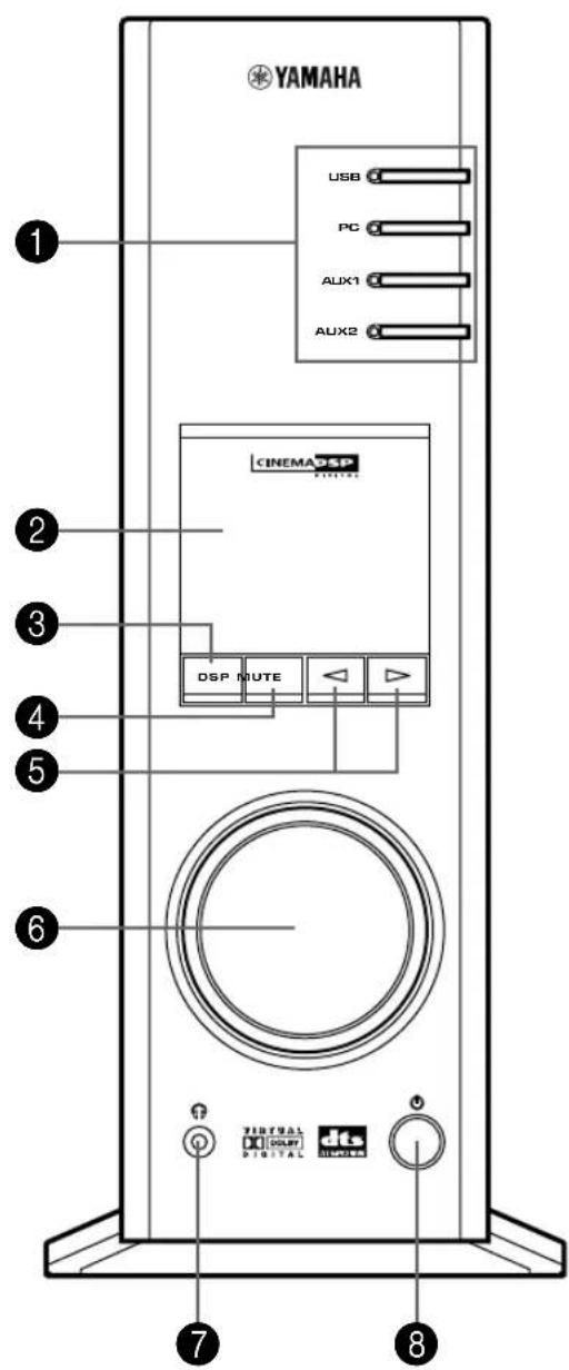
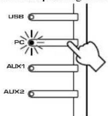
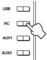
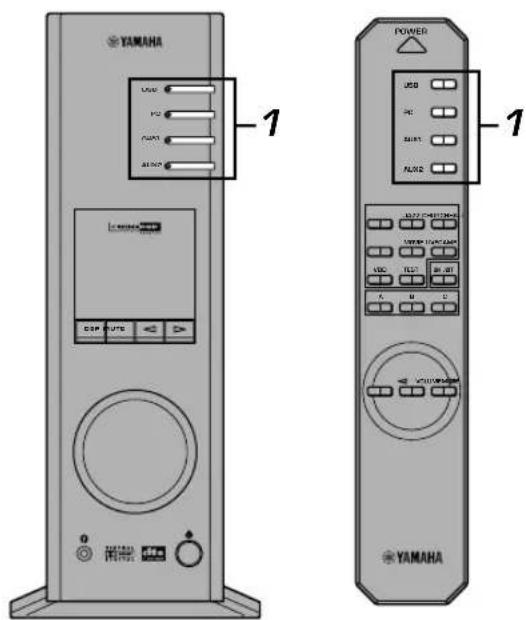
① Input selectors & indicators
These four keys, explained below, are used to select the input source. The indicator of the selected source lights up.
- USB key
This key selects input signals sent from your computer by way of the USB terminal.
- PC key
This key selects your computer as the input source. Pressing this key repeatedly selects the digital (DIGITAL PC COAX IN or DIGITAL PC OPT IN) or analog (ANALOG PC IN) input. The DIGITAL PC OPT IN has priority over the DIGITAL PC COAX IN, so if you connect to both inputs, the signal received at the DIGITAL PC OPT IN is used.
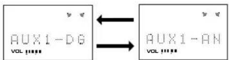
- AUX1 key
This key selects the equipment connected to the ANALOG AUX 1 IN or DIGITAL AUX 1 OPT IN connector as the input source. Pressing this key repeatedly selects the digital or analog input.
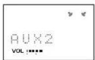
- AUX2 key
This key selects the equipment connected to the ANALOG AUX 2 IN connectors as the input source.
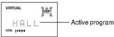
② Display
The display shows various settings, selected input source, sound field program and various other information.
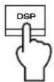
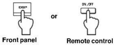
③ DSP key [front panel]
ON/OFF key [remote control]
This key activates the sound field programs produced by the internal DSP.
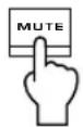
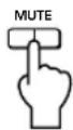
4 MUTE key
This key is used to cut off sound output temporarily. Turning the volume control on the front panel or pressing the VOLUME keys on the remote control restores sound output. Pressing this key again also restores sound output.
* Sound output will also be restored by changing the status of this unit between standby and power-on, changing the input source or the sound field program, and so on.
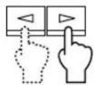
5 △ (Down/Up) keys
These keys are used to select sound field programs. These keys only work when the internal DSP is activated (when "DSP" is illuminated on the display).
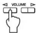
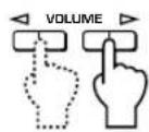
6 Volume control [front panel]
◀ VOLUME▶ (Down/Up) keys [remote control]
These control and keys adjust the speaker and headphone volume. The volume cannot be adjusted when this unit is in the standby mode.
7 Headphone jack
Stereo headphones can be connected to this mini-jack for private listening, with Virtual 3D effects specifically tailored for headphone listening.
8 Power switch( ) [front panel]
POWER key [remote control]
Each click of this switch changes the status of this unit between standby mode and power on.
* In the standby mode, this unit can be turned on remotely from your computer, using the supplied Application Software. Note that this unit uses a small amount of power in the standby mode.
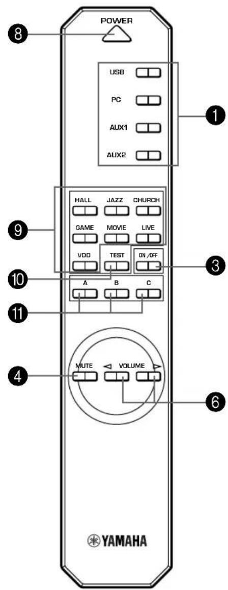
9 Sound field program selector keys
Each of these keys selects the corresponding sound field program.
10 TEST key
This key is used to output a test tone. The test tone is used when adjusting the volume balance between the left and right front speakers, or among all speakers in the system including the virtual rear speakers. (Refer to page 13 for details.)
11 Custom keys (A, B, C)

These keys are available when this unit and your computer are connected with the USB cable, and the supplied Application Software is installed on the computer.
Each of these keys can be programmed with a set of commands (input selector, sound field program, volume setting, etc.) by using the Application Software. After storing, simply pressing each key will execute the stored command.
* Refer to the online help of the Application Software for details.

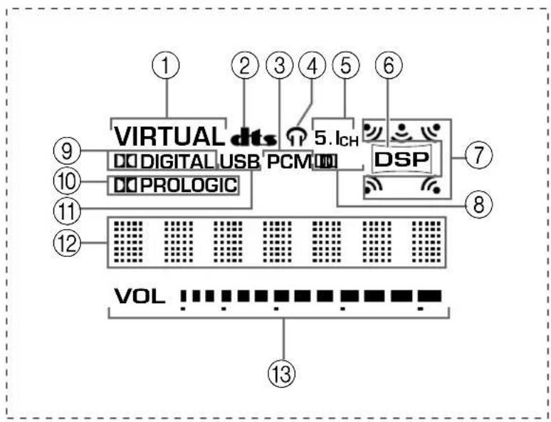
About the display
This section explains what the various display indicators mean.
flowchart
graph TD
    A["VIRTUAL dts"] --> B["Digital USB PCM"]
    B --> C["DSP"]
    C --> D["7"]
    C --> E["8"]
    C --> F["9"]
    C --> G["10"]
    C --> H["11"]
    C --> I["12"]
    C --> J["13"]
    style A fill:#f9f,stroke:#333
    style B fill:#ccf,stroke:#333
    style C fill:#cfc,stroke:#333
    style D fill:#fcc,stroke:#333
    style E fill:#cff,stroke:#333
    style F fill:#ffc,stroke:#333
    style G fill:#cfc,stroke:#333
    style H fill:#fcc,stroke:#333
    style I fill:#ffc,stroke:#333
    style J fill:#fcc,stroke:#333
① VIRTUAL
This indicator appears when this unit is using Virtual 3D.
② dt(BTS)
This indicator appears when an input signal is decoded with DTS.
③ PCM
This indicator appears when a PCM digital audio signal is selected as the input source.
④
This indicator appears when headphones are connected to the headphone jack of this unit.
⑤ 5.1CH
This indicator appears when a 5.1 channel digital audio signal is selected as the input source.
⑥ DSP
This indicator appears when the DSP is processing the input signal.
⑦ Sound output indicators
This indicator shows the currently used speakers (including virtual speakers).
⑧ D.
This indicator appears when an audio signal encoded with Dolby Digital is selected as the input source.
⑨ (DOLBY) DIGITAL
This indicator appears when an input signal is decoded with Dolby Digital.
⑩ (DOLBY) PROLOGIC
This indicator appears when an input signal is decoded with Dolby ProLogic.
⑪ USB
This indicator appears when audio signals are sent or received via the USB terminal.
⑫ Multi-information display
Various messages and information appear here.
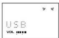
⑬ VOL (volume)
This indicator graphically displays the volume level setting.
Playing a source
This section explains how to turn on this unit and select input sources. If any external audio equipment is connected to this unit, turn it on first.
1 Turn on this unit.

Front panel
or

Remote control
The message “Hello” appears for a few seconds, and this unit returns to the state in which it was last used (e.g., the input source that was selected when this unit was turned off is selected).
2 Decrease the volume to minimum (MIN).

Front panel
or
Remote control
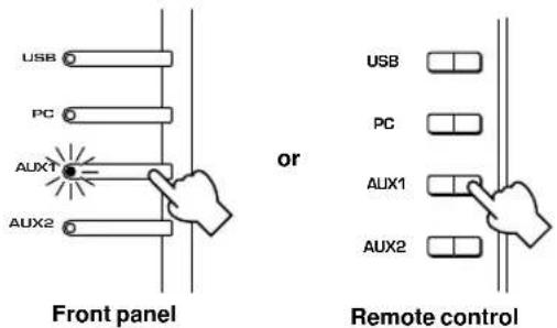
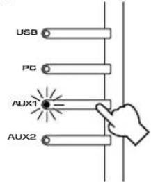
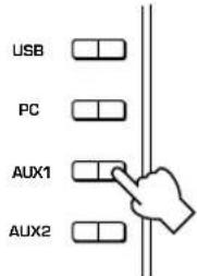
3 Select an input source by using the input selector keys.
The corresponding indicator on the front panel lights up.
Front panel
or
Remote control
Refer to the explanation on the right side for details about using the input selector keys.
4 Start the selected input source.
5 Adjust the volume to the desired level.

Front panel
or
Remote control
6 As you prefer, use a sound field program.
Refer to page 10 for details about the sound field programs.
About the input selector keys
Each of the input selector keys selects the following input signals.
USB: Press the USB key to select input signals at the USB terminal.
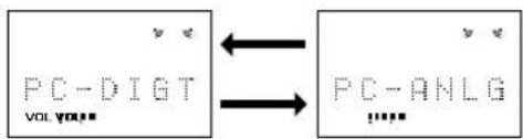
PC: Press the PC key repeatedly to select the PC inputs:
"PC_DIGT" and "PC_ANLG". PC_DIGT selects the DIGITAL PC COAX IN or DIGITAL PC OPT IN, and PC_ANLG selects the ANALOG PC IN.
Note: The DIGITAL PC OPT IN has priority over the DIGITAL PC COAX IN, so if you connect to both inputs, the signal received at the DIGITAL PC OPT IN is used.
AUX1: Press the AUX1 key repeatedly to select the inputs:
"AUX1_DG" and "AUX1_AN". AUX1_DG selects the equipment connected to the DIGITAL AUX 1 OPT IN, and AUX1_AN selects the equipment connected to the ANALOG AUX 1 IN connector as the input source.
AUX2: Press the AUX2 key to select the equipment connected to the ANALOG AUX 2 IN connectors as the input source.
Note
When an input selector key is pressed, the display shows the name of the selected input source for a short while, and then shows the currently selected sound field program.
When no sound field program is selected, "THROUGH" is shown on the display.

The names of input sources shown on the display can be changed with the Application Software. Refer to the Online Help of the Application Software for details.

■ To cut off sound output temporarily
Press the MUTE key. To restore sound output, turn the volume control on the front panel or press the VOLUME keys on the remote control. Pressing the MUTE key again also restores sound output.
Front panel
or
Remote control
Note
Sound output will also be restored by changing the status of this unit between standby and power-on modes, changing the input source or the sound field program, using the test tone, or using the A, B, C keys on the remote control.
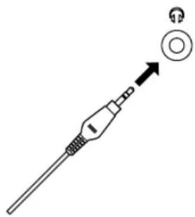
■ When you listen with headphones
Connect the headphones to the headphone jack. No sound will be outputted from the speakers.
natural_image
Diagram of a medical or laboratory probe with a circular component and an arrow pointing to it (no text or symbols present)Note
[DP-U50 only]
The PRE OUT terminals on the rear panel will output signals even if headphones are used.
■ When you have finished using this unit
Set this unit to the standby mode by pressing the power switch on the front panel or the POWER key on the remote control.

Front panel
or

Remote control
Note
When not planning to use this unit for a long period (i.e., vacation, etc.), disconnect the AC power plug from the wall outlet.

Setting USB MIX
When an input other than the USB terminal is selected, you can listen to the mixed signals from the selected input and from the USB terminal. Also, the mixing ratio of the signals from the USB terminal can be adjusted.
* Refer to the online help of the Application Software for details.
■ Setting graphic equalizer
You can adjust the frequency characteristics as you prefer by using the 7-band graphic equalizer.
* Refer to the online help of the Application Software for details.

Notes
- Some setting changes may be needed on the computer to reproduce signals sent from the computer to this unit via the USB connection. Refer to the separate “SET UP MANUAL” for details.
- Some setting changes may be needed on the computer to reproduce signals sent from the computer to this unit via a sound card, etc.
Automatic power saving function
If there is no operation on this unit's front panel, the remote control or the Application Software for about 24 hours with the power of this unit on, this unit will automatically be set to the standby mode.
Using sound field programs
This unit's built-in DSP (Digital Sound field Processor) can simulate various acoustic environments, including a concert hall and movie theater, with its seven sound field programs. For best results, choose a program appropriate for the selected audio source.
First follow steps 1–5 of "Playing a source" on page 8.
1 Turn on the DSP.
Front panel
or

Remote control
The name of the selected sound field program appears on the display.
2 Select the desired sound field program.
Front panel
or
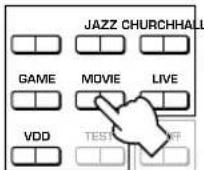
Remote control
Front panel: Pressing or repeatedly changes the program.
Remote control: Press the key of the desired program.
The following programs are available.
| Program | Feature | Note | |
| Hi-Fi DSP (for music sources) | HALL (CONCERT HALL EUROPE) | This program simulates the sound field of a medium-sized hall, with a beautiful and rich reverberation. | These programs create a sound field that feels real, just as if you were actually there. |
| JAZZ (JAZZ CLUB VILLAGE GATE) | This program simulates the sound field of a famous New York jazz club. | ||
| CHURCH (CHURCH ROYAUMONT) | This program simulates the sound field of a Gothic church, with the unique effect of sound reverberating back and forth in a domed ceiling. | ||
| CINEMA DSP (for video sources) | GAME (GAME AMUSEMENT) | This program adds depth and surround effects to computer games, enhancing the gaming experience. | For these sound field programs, a Yamaha DSP effect is applied to Dolby Pro Logic, Dolby Digital, DTS, and other surround sounds for motion-picture audio.*: HP3DWhen headphones are connected, this program changes to a simulation program called HP3D, which is specifically tailored for headphone listening. |
| MOVIE (MOVIE THEATER) | The realism provided by this program gives the impression that you're actually in the scene. | ||
| LIVE (LIVE CONCERT) | This program produces an enthusiastic atmosphere and lets you feel that you are in the midst of the action, as if attending an actual jazz or rock concert. | ||
| VDD [HP3D*](VIRTUAL DOLBY DIGITAL)DTS [HP3D*](DTS VIRTUAL 5.1) | This program simulates the effect of Dolby Digital and DTS and is ideal for DVD software encoded using Dolby Digital or DTS. |
Note
Just after selecting a program, the program name scrolls from right to left on the display, and then its short-version name lights up.
■ To turn off the DSP
Press the DSP key on the front panel or the ON/OFF key on the remote control. "THROUGH" appears on the display.

■ Adjusting DSP sound field parameters
The surround effect of each program or the Virtual 3D effect can be adjusted to the desired taste by using the Application Software. Refer to the online help of the Application Software for details.

Recording
Input sources (e.g., a computer or CD player) selected on this unit can be recorded by an MD recorder, tape deck, etc. connected to this unit. Also, input signals can be fed to your computer via the USB connection.
* When a source is recorded using a sound field program, sound field effects are recorded with the source.
■ Recording on an external recording unit
First turn on the external unit to be used, and then this unit.
1 Select the source to be recorded by using the input selector keys.
2 Start recording on a recording unit (an MD recorder, tape deck, etc.).
3 Start playing the input source.
■ Playing the recorded result via this unit
Select the input signals sent from the recording unit with the input selector keys.
Notes
- If input signals received at any digital input terminal other than the USB terminal is outputted at the digital output terminal, the sampling frequency for the output signals is the same as that for input signals.
- The sampling frequency for digital signals converted from analog signals on this unit is 44.1 kHz or 48 kHz.
- When digital input signals are outputted at the digital output terminal, track information (CD-text data, automatic track renewal when recording is made on an MD, etc.) is invalid if any sound field program (including the graphic equalizer effect) is used.
■ Recording on a computer (via the USB connection)
When recording or processing signals inputted to your computer via the USB connection, the following setting is needed on the computer.
○ Selecting Recording Device
When using Windows
- Click the Windows "Start" button and select "Settings", and then "Control Panel".
- Double-click the "Multimedia" icon (or the "Sounds and Multimedia" icon).
- Click the "Audio" tab and select "USB Audio Device" at "Preferred device" of "Recording" (or "Sound Recording").
When using a Macintosh
Select "USB Audio" as the input device at "Sound" on the Control Panel.
○ Setting of Recording Software
Select a sampling frequency from 44.1 kHz and 48 kHz. Select a resolution from 16 bits and 24 bits. The sampling frequency of 44.1 kHz with the resolution of 16 bits produces a sound quality comparable to the compact disc (CD).
1 Select the source to be recorded by using the input selector keys.
Front panel
or
Remote control
2 Start recording with the recording software on the computer.
3 Start playing the input source.
■ Playing the recorded result via this unit
Press the USB input selector key, and play the recorded result on the computer.
Notes
- If the number of USB channels is set to six, recording cannot be made via the USB connection. Reset the number of USB channels to two or four.
- To record digital input signals with a 48 kHz sampling frequency, the frequency of the input signals must be 48 kHz.
- To record sound signals received at an analog or digital input of the sound card etc., and not via the USB connection, select the corresponding device, such as "Sound Card", from "Preferred device" of "Recording" (or "Sound Recording") on the computer.
- The sampling frequency and resolution of signals recordable on the computer differ from operating systems. You can refer to the following Yamaha website for details about the related information.
- Please check the copyright laws in your country before recording, compact discs, radio, etc. Recording of copyright material may infringe copyright laws.
- You cannot make a recording from a CD-R, MD, etc. which is a copy of an audio CD, to another CD-R, MD, etc. via the USB connection or the digital terminal connection. Also, you cannot make a recording from an MD which is recorded with digital signals received via the USB connection, to another MD.
Adjusting surround effect
This unit features YAMAHA's unique "Virtual 3D" technology, which provides a virtual surround sound effect with only two speakers. In the sound field of the "Virtual 3D" mode, two virtual rear speakers are provided as well as two front speakers (L, R) to achieve the surround-sound effect.
To optimize the surround-sound effect, adjust the volume of each speaker in the sound field by listening to a series of test tones.
1 Press the TEST key on the remote control.
A test tone is outputted from the following speakers in turn.

Remote control

Front speaker (L) Virtual rear speaker (L) Front speaker (R) Virtual rear speaker (R)

2 When the test tone is outputted from the left (L ch) or right (R ch) front speaker:
Using the VOLUME keys on the remote control adjusts the volume balance between the left and right front speakers.
(Adjustable range: -12 to +12)
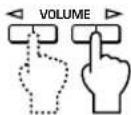
Remote control
3 When the test tone is outputted from the left (Ls ch) or right (Rs ch) virtual rear speaker: Using the VOLUME keys on the remote control adjusts the surround effect level.
(Adjustable range: -6 to +6)
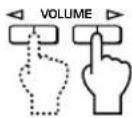
Remote control
4 When adjustments are finished, press the TEST key.

Remote control
Test tone stops.
Setting USB channel
Typical USB audio features multi-channel modes, such as four-channel and six-channel modes, in addition to a normal two-channel (stereo) mode. This unit is compatible with each of these modes. When a multi-channel mode is selected, you can receive surround sound of computer games compatible with the 4ch Direct Sound 3D and the surround sound (5.1 channels) of DVD video on this unit via the USB connection and enjoy it as virtual surround sound.
Note that some operating systems and software programs are not multi-channel compatible. Yamaha websites list the names of multi-channel compatible operating systems and software.
Notes
- MacOS9 does not support this feature. Only the two-channel mode can be used. Some versions of Windows also do not support the six and/or four-channel modes. You can refer to the following Yamaha website for details and related information.
- When the six channel mode is selected, recording cannot be made to the computer. To record, select the two- or four-channel mode.
How to set
* When playback or recording is performed on the computer via the USB connection, terminate the playback or recording software used on the computer.
1 Turn on this unit.

or

Front panel
Remote control
2 Hold down the USB input selector key until the current channel setting is shown (for about two
seconds).
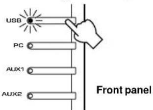
* When the display of this unit shows "USB" in red, the USB connection is currently used, disabling this USB channel setting function. Terminate the software used on the computer.
3 Press or repeatedly until the desired number of channels is shown on the display.
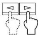
Front panel
The display changes as follows.
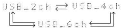
flowchart
graph TD
    A["USB_2ch"] <--> B["USB_4ch"]
    C["USB_6ch"] <--> D["USB_6ch"]
4 Hold down the USB input selector key until the selected number of channels disappears (for about two seconds).
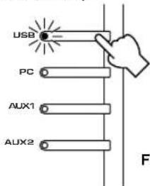
Front panel
Although no further operation is required, wait a short time until the computer completes the changes in the setting.
Notes
- When the number of channels is changed for the first time, the device driver for the USB audio is installed in the computer. Wait a short time until the computer completes the changes in the setting.
- Do not change the USB channel setting under any circumstance during playback or recording via the USB connection on the computer. If changed, the computer may hang.
Operating this unit with the Application Software
If this unit is connected to your computer via the USB connection and the Application Software is installed in your computer from the supplied CD-ROM, you can operate this unit with the Application Software from your computer. Moreover, the Application Software, once installed on your computer, offers various settings unavailable from this unit or the remote control. (For instructions on how to install the Application Software, see the separate "SET UP MANUAL".)
This section briefly explains how to use the Application Software, the setting screens, and the available functions. For further details, refer to the Online Help of the Application Software.
Notes
- The screen images shown in this section are of the basic screens for the Windows version. The Macintosh version slightly differs in button arrangement, etc.
- The screen design, functions, etc., are subject to change due to version upgrades.
About the Main Panel
The Main Panel allows you to perform the following basic operations.
Tabs are shown at the bottom of the detailed-setting screen. To make detailed settings of the desired function available from any detailed-setting screen, click on the tab for the function.
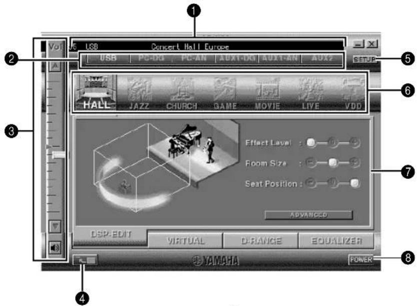
1 Display
This section shows the current status of the volume, input selectors, sound field programs, etc. by characters.
② Input selector
The input selector allows you to directly change the input source.
③ Volume control
You can adjust the volume by dragging the indicator or by clicking the up (▲and down ( ) ▼rows.
You can also alternately turn on and off the speakers by clicking the speaker icon below.
4 Changing the panel size
You can minimize the size of the Main Panel.
5 SETUP
Open this panel to change available settings in the Setup panel. (See page 18 for details on the Setup panel.)
6 DSP selector
You can directly select a DSP sound field program.
7 Detailed-setting screens
Select one of the detailed-setting screen tabs at the bottom of the current detailed-setting screen. The new detailed-setting screen will be displayed, where you can make detailed settings of the function.
DSP-EDIT: For adjusting the DSP sound field parameters (See page 16.)
VIRTUAL: For adjusting the virtual 3D (See page 17.)
D-RANGE: For adjusting the dynamic range (See page 17.)
EQUALIZER: For operating the graphic equalizer (See page 17.)
8 POWER
Each click changes the status of the main unit between standby and power-on.
Adjusting DSP sound field parameters
You can adjust various parameters of the DSP sound field programs.
The default parameters of the sound field programs provide great sound, but it is also possible to fine-tune the parameters to suit the acoustics of the room, individual preferences, and program source. Parameter adjustment is required for each selected sound field program.
How to adjust parameters
- Select the program whose parameters you wish to adjust. (Parameter adjustment is effective for the currently selected program only.)
- Select the DSP-EDIT tab at the bottom of the Main Panel. The basic parameter screen appears.
- This screen allows you to adjust the basic parameters. Open the "ADVANCED SETTING" panel for adjusting the detailed parameters.
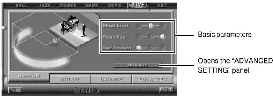
Basic parameters
| Effect Level Selects the level of effect sound from the three levels. | |
| Room Size Selects the apparent size of the listening space from the three levels. | |
| Seat Position Selects the simulated listening position from the three positions. |
Select a parameter by clicking its name, and adjust the parameter by sliding the indicator at the bottom of the panel.
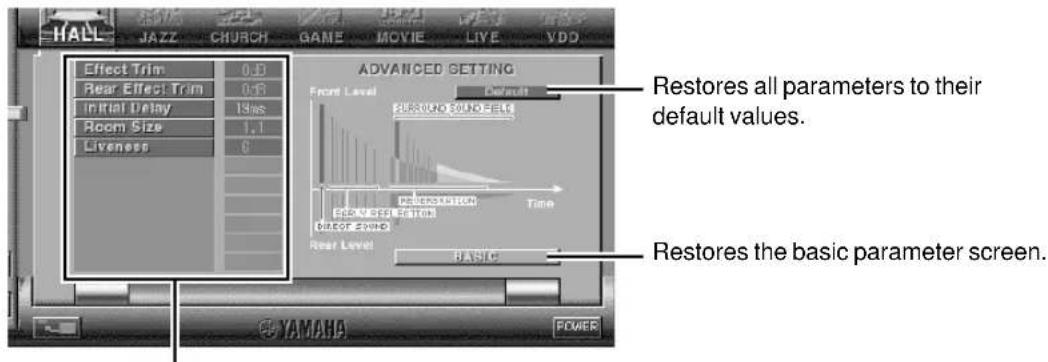
Detailed parameters
The following parameters are available on the "ADVANCED SETTING" panel. Depending on the selected program and input signals, not all of the parameters can be adjusted.
| Effect Trim Makes fine adjustment of the level of the overall effect sound. | |
| Rear Effect Trim Makes fine adjustment of the level of the rear effect sound. | |
| Initial Delay Adjusts the apparent distance from the sound source to the walls. | |
| Room Size Adjusts the apparent size of the listening space. | |
| Liveness Adjusts the apparent reflectivity of the walls. | |
| Surround Delay Adjusts the delay time of the surround sound field. | |
| S. Initial Delay (Surround Initial Delay) | Adjusts the initial delay time of the surround sound field. |
| S. Room Size (Surround Room Size) Adjusts the apparent size of the surround sound field. | |
| Reverb Time Adjusts the duration of reverberations. | |
| Reverb Level Adjusts the level of reverberations. | |
| Reverb Delay | Adjusts the delay time of reverberations. |
Adjusting the virtual 3D effect
The surround sound effect of the virtual 3D sound field is affected by the room configuration and the position of the listener, resulting in sound unique to each environment. The procedure below shows you how to adjust the effect of the virtual 3D to suit your preferences and environment.
Select the VIRTUAL tab at the bottom of the Main Panel. The following screen appears.
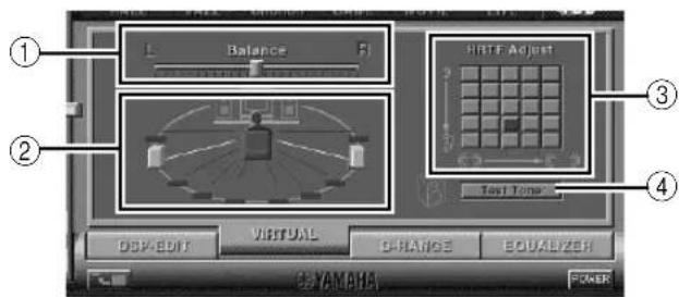
① Balance adjustment
You can adjust the volume balance between the right and left speakers.
② Virtual rear speaker position setting
You can set the position of the virtual rear speakers (the speakers are positioned symmetrically.)
③ HRTF (Head-related Transfer Function) adjustment
You can make an adjustment to personal characteristics.
④ Test tone
You can output a test tone successively from the speakers at their current positions, allowing setting and adjustment while listening to the tone.
Adjusting the dynamic range
You can set the dynamic range for playing a source with Dolby Digital decoded. This is especially effective for low-volume listening. Select the D-RANGE tab at the bottom of the Main Panel. The following screen appears.
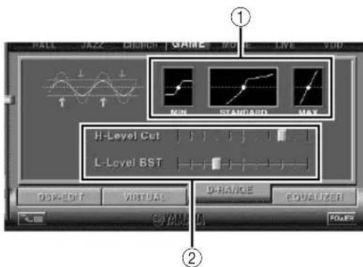
① Dynamic range setting
Select the dynamic range for playing a source with Dolby Digital decoded from MIN, STANDARD, and MAX. The MAX setting provides a dynamic range of a movie theater while MIN provides a dynamic range suitable for late night, low-volume listening.
② Dynamic range adjustment
This setting becomes available when you choose STANDARD for the dynamic range. This adjusts high-level cut scale (H-LEVELCut) and low-level boost scale (L-LEVELBST), allowing you to freely adjust the dynamic range between MAX and MIN.
Operating the graphic equalizer
The 7-band graphic equalizer allows you to set the frequency characteristics according to the type of the music that is played and to compensate for the room characteristics and the speakers' frequency characteristics.
This panel is always shown when no DSP sound field program is selected. When a DSP sound field program is selected, selecting the EQUALIZER tab at the bottom of the Main Panel will show this panel.
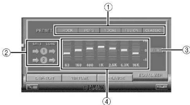
① Preset patterns
Five patterns of frequency characteristics have been preset for different types of music, such as "ROCK" and "POPS". Click a button to select the effect that suits the music type.
② Storing and calling user's patterns
You can store and call up to two patterns of frequency characteristics you specify.
③ FLAT
This makes the frequency response curves flat.
④ Graphic equalizer
The 7-band equalizer allows you to set your desired frequency response curves. By dragging the indicator for each frequency band, you can adjust the frequencies within the range of +6 to -6 dB.
Setting adjustment on the Setup panel
When you click SETUP of the Main Panel, the Setup panel appears, allowing you to perform the following settings.
Edit Names of Input Sources
You can assign a name consisting up to seven characters to each input source. For example, if a tape deck is connected to the AUX 1 terminals, you can change the name, AUX 1, to TAPE. As this name change information is sent to the main unit, the display on the main unit changes accordingly.
Volume Settings
USB Mix
When USB Mix is on, even if signals received at input terminal(s) other than the USB terminal when it is selected, you can mix the input signals from that selection with the signals from the computer via the USB connection and play the mixed signals. For example, while you are listening to music from the tape deck connected to AUX 1, mail arrival beeps and warning beeps are also available.
Clicking the check box to enter the check mark in the box will turn on the USB Mix. This status allows you to adjust the volume level of the signals from the USB connection. (As this adjusts the volume balance between the selected input signals and the input signals from the USB connection, it does not affect the volume when USB is selected by the input selector keys.)
Clicking the check box to delete the check mark will turn off the USB Mix. In this status, the signals from the USB connection can be played only when USB is selected by the input selector keys.
■ Maximum Volume Setting
When adjusting the volume on the Application Software, you may inadvertently turn up the volume too high. To avoid this, you can use this function to set a maximum volume for the Application Software.
■ Digital Volume Setting
This allows you to digitally turn up and down the volume in the DSP. Take care not to turn up the volume when the level of the digital input signal is high as it may cause sound distortion due to digital processing. If sound distortion occurs, turn down the volume.
USB Setting
■ USB Multi-Channel Setting (for Windows only)
This allows you to select the number of channels for sending playback signals via the USB connection from two, four, and six channels. (Note that you cannot record signals from the USB connection on the computer when six channels are selected.)
Custom Keys
■ Skin Selection
This allows you to select the skin (the design of the background picture of the Application Software) from several preset patterns.
■ Setting Remote Control Custom keys
This allows you to store a set of commands (input selector, sound field program, volume setting, etc.) to each of the A, B and C keys on the remote control. After storing, simply pressing each key will execute the stored command.
Note
The screen design, functions, etc. are subject to change due to software upgrades. For details, refer to the Online Help of the Application Software.
Troubleshooting
Refer to the chart below if this unit does not function properly. If the problem you are experiencing is not listed below or if the instructions given below do not help, disconnect the power cord and contact your authorized YAMAHA dealer or service center.
| Problem | Cause | Remedy |
| The unit cannot be turned on though the power switch is pressed. | The power cord is not plugged in or is not completely inserted. | Firmly plug in the power cord. |
| No sound. | This unit is in the standby mode. | Turn on this unit by pressing the power switch on the front panel or the POWER key on the remote control. |
| Incorrect output cord connections. | Connect the cords properly. If the problem persists, the cords may be defective. | |
| The muting function of this unit is on. | Turn off the muting by pressing the MUTE key. | |
| Headphones are connected to the headphone jack of this unit. | Disconnect the headphones from the headphone jack to output sound from the speakers. | |
| The volume is set to minimum. | Increase the volume. | |
| The playback source is not selected by the input selector keys. | Select the playback source using the input selector keys. | |
| When PC is selected as the input source, check that the digital or analog input is correctly selected. | ||
| The power of the equipment selected as the input source is off. | Turn on the equipment. | |
| No surround effect. | The DSP is off. | Turn on the DSP. |
| When making a recording from an audio CD to an MD, CD-R, etc., all tracks are recorded as one track. | A DSP sound field program is selected or the built-in graphic equalizer is used. | Turn off the DSP and the graphic equalizer. |
| Program sources on an MD, CD-R, etc. which is a copy of an audio CD, cannot be recorded on the computer via the USB connection. | You cannot make a recording from a CD-R, MD, etc. which is a copy of an audio CD, to another CD-R, MD, etc. via the USB connection or the digital terminal connection. | Record the signals of such an MD, CD-R, etc. on the computer by sending the signals via an analog connection. |
| Signals inputted to your computer via the USB connection cannot be recorded on the computer. | Incorrect setting of the recording device on the computer. | Correctly set the recording device on the computer. [Refer to “Recording on computer (via the USB connection”) on page 12.] |
| No effect of Dolby Digital or DTS though the sound field program “VDD” is selected. | The playback source is encoded with neither Dolby Digital nor DTS. | Use a source encoded with Dolby Digital or DTS. |
| Different sounds are heard together. | Sound from the computer via the USB connection may be mixed with sound from other sources because the “USB Mix” setting is set to “ON” with the Application Software. | Set the “USB Mix” setting to “OFF” if you do not want to hear mixed sounds. |
| Left and right volume levels are different. | The level balance is not set to center on the “Balance” setting on the VIRTUAL panel in the Application Software. | Set the level balance to center. |
| Problem | Cause | What to Do |
| The remote control does not work. | The batteries of the remote control are weak. | Replace the batteries with new ones. |
| The remote control does not function properly. | Wrong distance or angle. | The remote control will function from a maximum range of 6 meters and no more than 30 degrees off-axis from the front panel. |
| Direct sunlight or strong light (of an inverter type fluorescent lamp etc.) is striking the remote control sensor of the main unit. | Reposition the main unit. |
Specifications
[AP-U70]
Minimum RMS Output Power per Channel
20W + 20W (20 Hz–20 kHz, 6Ω, 0.4% THD)
Maximum Power 26W + 26W (1 kHz, 6Ω, 10% THD)
Input Sensitivity/Input Impedance
PC IN, AUX1 IN, AUX2 IN (ANALOG) 150 mV/35 kΩ
Maximum Input Signal
PC, AUX1, AUX2 2.1V or more (1 kHz)
Output Level/Output Impedance
REC OUT 150 mV/2.0 kΩ
SUBWOOFER OUTPUT 2.0V/1.7 kΩ (50 Hz)
Headphone Jack Output Level/Output Impedance
ANALOG PC IN, etc. 320 mV/61Ω (1 kHz, 150 mV)
Frequency Response
USB, DIGITAL IN (PC, AUX1) to SP Output
20 Hz–20 kHz (±1.0 dB)
Total Harmonic Distortion (1 kHz, 20 kLPF)
USB, DIGITAL IN (PC, AUX1) to SP Output
0.06% or less (4V/6Ω)
Signal-to-Noise Ratio
USB to SP Output 85 dB or more (11V/6Ω)
PC IN, AUX1 IN (DIGITAL) to SP Output
90 dB or more (11V/6Ω)
Residual Noise (IHF-A Network)
-68 dB or less (SP Output, L/R)
Power Supply
[U.S.A. and Canada models] AC 120V, 60 Hz
[Europe and U.K. models] AC 230V, 50 Hz
[Australia model] AC 240V, 50 Hz
Power Consumption
[U.S.A. and Canada models] 60W
[Europe, U.K. and Australia models] 55W
Dimensions (W × H × D)
120 × 294 × 355 mm
(4-3/4" × 11-9/16" × 14")
Weight 5.5 kg (12 lbs. 2 oz.)
Accessories
CD-ROM (Windows/Macintosh-hybrid)
USB cable
Remote control
Battery × 2
Specifications are subject to change without notice.
[DP-U50]
Output Level/Output Impedance
PRE OUT 2.0V/2.0 kΩ
SUBWOOFER OUTPUT 2.0V/1.7 kΩ (50 Hz)
Input Sensitivity/Input Impedance
PC IN, AUX1 IN, AUX2 IN (ANALOG) 150 mV/35 kΩ
Maximum Input Signal
PC, AUX1, AUX2 2.1V or more (1 kHz)
Headphone Jack Output Level/Output Impedance
ANALOG PC IN, etc. 320 mV/61Ω (1 kHz, 150 mV)
Frequency Response
USB, DIGITAL IN (PC, AUX1) to PRE OUT
20 Hz–20 kHz (±1.0 dB)
Total Harmonic Distortion (1 kHz, 20 kLPF)
USB, DIGITAL IN (PC, AUX1) to PRE OUT
0.01% or less
Signal-to-Noise Ratio
USB to PRE OUT 100 dB or more
PC IN, AUX1 IN (DIGITAL) to PRE OUT
110 dB or more
Residual Noise (IHF-A Network)
20×V or less (PRE OUT, L/R)
Power Supply
[U.S.A. and Canada models] AC 120V, 60 Hz
[Europe and U.K. models] AC 230V, 50 Hz
[Australia model] AC 240V, 50 Hz
Power Consumption 20W
Dimensions (W × H × D)
120 × 294 × 355 mm
(4-3/4" × 11-9/16" × 14")
Weight 5.0 kg (11 lbs.)
Accessories CD-ROM (Windows/Macintosh-hybrid)
USB cable
Remote control
Battery × 2
Specifications are subject to change without notice.
natural_image
Diagram of a medical or laboratory device with a needle inserted, showing a circular component and an arrow pointing to it (no text or symbols present)Remarque
[DP-U50 uniquement]
PC IN, AUX1 IN, AUX2 IN (ANALOG) 150 mV/35 kΩ
REC OUT 150 mV/2.0 kΩ
SUBWOOFER OUTPUT 2,0 V/1,7 kΩ (50 Hz)
Dimensions (L × H × P)
120 × 294 × 355 mm
Poids
5,5 kg
Accessoires
CD-ROM (Hybride Windows/Macintosh)
Câble USB
Télécommande
Piles × 2
PRE OUT 2,0 V/2,0 kΩ
SUBWOOFER OUTPUT 2,0 V/1,7 kΩ (50 Hz)
PC IN, AUX1 IN, AUX2 IN (ANALOG) 150 mV/35 kΩ
Digital Sound Field Processing
(DSP)......4
BEDIENUNGSELEMENTE UND IHRE FUNKTIONEN
Digital Sound Field Processing (DSP)
natural_image
Diagram of a medical or laboratory probe with a circular connector and an arrow indicating direction (no text or symbols)Hinweis
PC IN, AUX1 IN, AUX2 IN (ANALOG) 150 mV/35 kΩ
Maximaleingangssignal
PC IN, AUX1 IN (DIGITAL) an – SP-Ausgang
PRE OUT 2,0 V/2,0 kΩ
SUBWOOFER OUTPUT 2,0 V/1,7 kΩ (50 Hz)
PC IN, AUX1 IN, AUX2 IN (ANALOG) 150 mV/35 kΩ
Maximaleingangssignal
USB, DIGITAL IN (PC, AUX1) an PRE OUT
20 Hz–20 kHz (±1,0 dB)
Klirrfaktor (1 kHz, 20 kLPF)
USB, DIGITAL IN (PC, AUX1) an PRE OUT
0,01% oder weniger
Rauschabstand
PC IN, AUX1 IN (DIGITAL) an PRE OUT
110 dB oder mehr
Digital Sound Field Processing
(DSP)......4
REGLAGE OCH DERAS FUNKTIONER
Frontpanelen & fjärrkontrollen .... 5
Displayen 7
GRUNDBRUK
Digital Sound Field Processing (DSP)
natural_image
Simple line drawing of a medical or laboratory probe with a circular component and an arrow pointing to it (no text or symbols)Anmärkning
[Endast DP-U50]
PC IN, AUX1 IN, AUX2 IN (ANALOG) 150 mV/35 kΩ
Max insignalnivå
PC, AUX1, AUX2 2,1 V eller mer (1 kHz)
Utnivå/utimpedans
REC OUT 150 mV/2,0 kΩ
SUBWOOFER OUTPUT 2,0 V/1,7 kΩ (50 Hz)
Hörlurar, utnivå/utimpedans
ANALOG PC IN osv. 320 mV/61 Ω (1 kHz, 150 mV)
Frekvensåtergivning
USB, DIGITAL IN (PC, AUX1) till
Total harmonisk distorsion (1 kHz, 20 kLPF)
USB, DIGITAL IN (PC, AUX1) till
PRE OUT 2,0 V/2,0 kΩ
SUBWOOFER OUTPUT 2,0 V/1,7 kΩ (50 Hz)
PC IN, AUX1 IN, AUX2 IN (ANALOG) 150 mV/35 kΩ
Max insignalnivå
PC, AUX1, AUX2 2,1 V eller mer (1 kHz)
Hörlurar, utnivå/utimpedans
ANALOG PC IN osv. 320 mV/61 Ω (1 kHz, 150 mV)
Frekvensåtergivning
USB, DIGITAL IN (PC, AUX1) till PRE OUT
20 Hz–20 kHz (±1,0 dB)
Total harmonisk distorsion (1 kHz, 20 kLPF)
USB, DIGITAL IN (PC, AUX1) till PRE OUT
0,01% eller mindre
natural_image
Diagram of a medical or laboratory probe with an arrow pointing to a circular component (no text or symbols present)Nota
③ Regolazione HRTF (Head-related Transfer Function)
PRE OUT 2,0 V/2,0 kΩ
USCITA DEL SUBWOOFER 2,0 V/1,7 kΩ (50 Hz)
PC IN, AUX1 IN, AUX2 IN (ANALOG) 150 mV/35 kΩ
ANALOG PC IN, ecc. 320 mV/61 Ω (1 kHz, 150 mV)
USB, DIGITAL IN (PC, AUX1) a PRE OUT
0,01% o meno
PC IN, AUX1 IN (DIGITAL) a PRE OUT
110 dB o più
Rumore residuo (rete IHF-A)
20 ∝ V o meno (PRE OUT, L/R)
Dimensioni (W × H × D)
120 × 294 × 355 mm
Peso 5,0 kg
Accessori CD-ROM (Windows/Macintosh-ibrido)
Cavo USB
Telecomando
Batteria × 2
natural_image
Diagram of a medical or laboratory probe with a circular connector and an arrow indicating direction (no text or symbols)Nota
[Solo DP-U50]
PC IN, AUX1 IN, AUX2 IN (ANALÓGICO) 150 mV/35 kΩ
ANALÓGICO PC IN, etc. 320 mV/61 Ω (1 kHz, 150 mV)
PC IN, AUX1 IN (DIGITAL) a salida SP
PRE OUT 2,0 V/2,0 kΩ
SALIDA DE SUBWOOFER 2,0 V/1,7 kΩ (50 Hz)
PC IN, AUX1 IN, AUX2 IN (ANALÓGICO) 150 mV/35 kΩ
ANALÓGICO PC IN, etc. 320 mV/61 Ω (1 kHz, 150 mV)
USB, DIGITAL IN (PC, AUX1) a PRE OUT
20 Hz–20 kHz (±1,0 dB)
USB, DIGITAL IN (PC, AUX1) a PRE OUT
0,01% o menos
PC IN, AUX1 IN (DIGITAL) a PRE OUT
110 dB o más
Ruido residual (Red IHF-A)
20 ∝ V o menos (PRE OUT, L/R)
Alimentación
natural_image
Diagram of a medical or laboratory probe with a circular connector and an arrow indicating direction (no text or symbols)Opmerking
PC IN, AUX1 IN, AUX2 IN (ANALOG) 150 mV/35 kΩ
Maximaal ingangssignaal
PC, AUX1, AUX2 2,1 V of meer (1 kHz)
90 dB of meer (11 V/6Ω)
Eigenruis (IHF-A-netwerk)
-68 dB of minder (SP-uitgang, L/R)
Voedingsvereisten
PRE OUT 2,0 V/2,0 kΩ
SUBWOOFER OUTPUT 2,0 V/1,7 kΩ (50 Hz)
PC IN, AUX1 IN, AUX2 IN (ANALOG) 150 mV/35 kΩ
Maximaal ingangssignaal
PC, AUX1, AUX2 2,1 V of meer (1 kHz)
- ■ Adjusting USB MIX LEVEL
- Features
- \* VIATUAL DO DOLBY DIGITAL
- \*\* dts VIRTUAL 5.1
- CONTENTS
- OUTLINE OF THIS UNIT
- CONTROLS AND THEIR FUNCTIONS
- BASIC OPERATION
- ADVANCED OPERATION
- APPENDIX
- CAUTION: Read this before operating this unit
- For U.K. customers
- SPECIAL INSTRUCTIONS FOR U.K. MODEL
- IMPORTANT:
- For Canadian Customers
- Main features of this unit
- [For DP-U50 only]
- Virtual 3D
- Digital Sound Field Processing (DSP)
- Front panel & Remote control
- ① Input selectors & indicators
- - USB key
- - PC key
- - AUX1 key
- - AUX2 key
- ② Display
- ③ DSP key [front panel]
- ON/OFF key [remote control]
- MUTE key
- △ (Down/Up) keys
- Volume control [front panel]
- Headphone jack
- Power switch( ) [front panel]
- POWER key [remote control]
- Sound field program selector keys
- TEST key
- Custom keys (A, B, C)
- About the display
- Playing a source
- About the input selector keys
- Note
- ■ To cut off sound output temporarily
- ■ When you listen with headphones
- [DP-U50 only]
- ■ When you have finished using this unit
- Setting USB MIX
- ■ Setting graphic equalizer
- Notes
- Automatic power saving function
- Using sound field programs
- ■ To turn off the DSP
- ■ Adjusting DSP sound field parameters
- Recording
- ■ Recording on an external recording unit
- ■ Playing the recorded result via this unit
- ■ Recording on a computer (via the USB connection)
- ○ Selecting Recording Device
- When using Windows
- When using a Macintosh
- ○ Setting of Recording Software
- Select the source to be recorded by using the input selector keys.
- Start recording with the recording software on the computer.
- Start playing the input source.
- Adjusting surround effect
- Press the TEST key on the remote control.
- When the test tone is outputted from the left (L ch) or right (R ch) front speaker:
- When the test tone is outputted from the left (Ls ch) or right (Rs ch) virtual rear speaker: Using the VOLUME keys on the remote control adjusts the surround effect level.
- When adjustments are finished, press the TEST key.
- Setting USB channel
- How to set
- Turn on this unit.
- Hold down the USB input selector key until the current channel setting is shown (for about two
- Press or repeatedly until the desired number of channels is shown on the display.
- Hold down the USB input selector key until the selected number of channels disappears (for about two seconds).
- Operating this unit with the Application Software
- About the Main Panel
- Display
- ② Input selector
- ③ Volume control
- Changing the panel size
- SETUP
- DSP selector
- Detailed-setting screens
- POWER
- Adjusting DSP sound field parameters
- How to adjust parameters
- Detailed parameters
- Adjusting the virtual 3D effect
- Adjusting the dynamic range
- Operating the graphic equalizer
- Setting adjustment on the Setup panel
- Edit Names of Input Sources
- Volume Settings
- USB Mix
- ■ Maximum Volume Setting
- ■ Digital Volume Setting
- USB Setting
- ■ USB Multi-Channel Setting (for Windows only)
- Custom Keys
- ■ Skin Selection
- ■ Setting Remote Control Custom keys
- Troubleshooting
- Specifications
- [AP-U70]
- [DP-U50]
- Remarque
- [DP-U50 uniquement]
- BEDIENUNGSELEMENTE UND IHRE FUNKTIONEN
- Hinweis
- REGLAGE OCH DERAS FUNKTIONER
- GRUNDBRUK
- Anmärkning
- [Endast DP-U50]
- Nota
- [Solo DP-U50]
- Opmerking
Brand : YAMAHA
Model : APU70
Category : Audio System