USER MANUAL VSX819HK PIONEER
Register your product at:
www.pioneerelectronics.com (US)
www.pioneerelectronics.ca (Canada)
- Protect your new investment
The details of your purchase will be on file for reference in the event of an insurance claim such as loss or theft.
- Receive free tips, updates and service bulletins on your new product
- Improve product development
Your input helps us continue to design products that meet your needs.
- Receive a free Pioneer newsletter
Registered customers can opt in to receive a monthly newsletter.
www.pioneerelectronics.com (US)
www.pioneerelectronics.ca (Canada)
This equipment is not waterproof. To prevent a fire or shock hazard, do not place any container filled with liquid near this equipment (such as a vase or flower pot) or expose it to dripping, splashing, rain or moisture.
D3-4-2-1-3. B. En
WARNING
Before plugging in for the first time, read the following section carefully.
The voltage of the available power supply differs according to country or region. Be sure that the power supply voltage of the area where this unit will be used meets the required voltage (e.g., 230 V or 120 V) written on the rear panel. D3-4-2-1-4_A_En
This product is for general household purposes. Any failure due to use for other than household purposes (such as long-term use for business purposes in a restaurant or use in a car or ship) and which requires repair will be charged for even during the warranty period.
K041_En
If the AC plug of this unit does not match the AC outlet you want to use, the plug must be removed and appropriate one fitted. Replacement and mounting of an AC plug on the power supply cord of this unit should be performed only by qualified service personnel. If connected to an AC outlet, the cut-off plug can cause severe electrical shock. Make sure it is properly disposed of after removal. The equipment should be disconnected by removing the mains plug from the wall socket when left unused for a long period of time (for example, when on vacation). D3-4-2-2-1a_A_En
WARNING: Handling the cord on this product or cords associated with accessories sold with the product will expose you to chemicals listed on proposition 65 known to the State of California and other governmental entities to cause cancer and birth defect or other reproductive harm.
Wash hands after handling
D36-P4_A_En
IMPORTANT NOTICE - THE SERIAL NUMBER FOR THIS EQUIPMENT IS LOCATED IN THE REAR. PLEASE WRITE THIS SERIAL NUMBER ON YOUR ENCLOSED WARRANTY CARD AND KEEP IN A SECURE AREA. THIS IS FOR YOUR SECURITY. D1-4-2-6-1_En
NOTE: This equipment has been tested and found to comply with the limits for a Class B digital device, pursuant to Part 15 of the FCC Rules. These limits are designed to provide reasonable protection against harmful interference in a residential installation. This equipment generates, uses, and can radiate radio frequency energy and, if not installed and used in accordance with the instructions, may cause harmful interference to radio communications. However, there is no guarantee that interference will not occur in a particular installation. If this equipment does cause harmful interference to radio or television reception, which can be determined by turning the equipment off and on, the user is encouraged to try to correct the interference by one or more of the following measures:
- Reorient or relocate the receiving antenna.
– Increase the separation between the equipment and receiver.
- Connect the equipment into an outlet on a circuit different from that to which the receiver is connected.
- Consult the dealer or an experienced radio/TV technician for help.
D8-10-1-2_En
This Class B digital apparatus complies with Canadian ICES-003.
Alterations or modifications carried out without appropriate authorization may invalidate the user's right to operate the equipment. D8-10-2_En
CAUTION: This product satisfies FCC regulations when shielded cables and connectors are used to connect the unit to other equipment. To prevent electromagnetic interference with electric appliances such as radios and televisions, use shielded cables and connectors for connections. D8-10-3
This device complies with part 15 of the FCC Rules. Operation is subject to the following two conditions: (1) This device may not cause harmful interference, and (2) this device must accept any interference received, including interference that may cause undesired operation.
Product Name: AUDIO/VIDEO MULTI-CHANNEL RECEIVER
Model Number: VSX-819H-K
Responsible Party Name: PIONEER ELECTRONICS SERVICE, INC.
Address: 1925 E. DOMINGUEZ ST. LONG BEACH, CA 90801-1760, U.S.A.
Phone: 1-800-421-1404
IMPORTANT

The lightning flash with arrowhead symbol, within an equilateral triangle, is intended to alert the user to the presence of uninsulated "dangerous voltage" within the product's enclosure that may be of sufficient magnitude to constitute a risk of electric shock to persons.
CAUTION
RISK OF ELECTRIC SHOCK DO NOT OPEN
CAUTION:
TO PREVENT THE RISK OF ELECTRIC SHOCK, DO NOT REMOVE COVER (OR BACK). NO USER-SERVICEABLE PARTS INSIDE. REFER SERVICING TO QUALIFIED SERVICE PERSONNEL.

The exclamation point within an equilateral triangle is intended to alert the user to the presence of important operating and maintenance (servicing) instructions in the literature accompanying the appliance.
D3-4-2-1-1_En-A
IMPORTANT SAFETY INSTRUCTIONS
1) Read these instructions.
2) Keep these instructions.
3) Heed all warnings.
4) Follow all instructions.
5) Do not use this apparatus near water.
6) Clean only with dry cloth.
7) Do not block any ventilation openings. Install in accordance with the manufacturer's instructions.
8) Do not install near any heat sources such as radiators, heat registers, stoves, or other apparatus (including amplifiers) that produce heat.
9) Do not defeat the safety purpose of the polarized or grounding-type plug. A polarized plug has two blades with one wider than the other. A grounding type plug has two blades and a third grounding prong. The wide blade or the third prong are provided for your safety. If the provided plug does not fit into your outlet, consult an electrician for replacement of the obsolete outlet.
10) Protect the power cord from being walked on or pinched particularly at plugs, convenience receptacles, and the point where they exit from the apparatus.
11) Only use attachments/accessories specified by the manufacturer.
12) Use only with the cart, stand, tripod, bracket, or table specified by the manufacturer, or sold with the apparatus. When a cart is used, use caution when moving the cart/apparatus combination to avoid injury from tip-over.

13) Unplug this apparatus during lightning storms or when unused for long periods of time.
14) Refer all servicing to qualified service personnel. Servicing is required when the apparatus has been damaged in any way, such as power-supply cord or plug is damaged, liquid has been spilled or objects have fallen into the apparatus, the apparatus has been exposed to rain or moisture, does not operate normally, or has been dropped. P1-4-2-2. En
WARNING
To prevent a fire hazard, do not place any naked flame sources (such as a lighted candle) on the equipment.
D3-4-2-1-7a_A_En
VENTILATION CAUTION
When installing this unit, make sure to leave space around the unit for ventilation to improve heat radiation (at least 60 cm at top, 10 cm at rear, and 30 cm at each side).
WARNING
Slots and openings in the cabinet are provided for ventilation to ensure reliable operation of the product, and to protect it from overheating. To prevent fire hazard, the openings should never be blocked or covered with items (such as newspapers, table-cloths, curtains) or by operating the equipment on thick carpet or a bed. D3-4-2-1-7b_A_En
Operating Environment
Operating environment temperature and humidity: +5 °C to +35 °C (+41 °F to +95 °F); less than 85 %RH (cooling vents not blocked)
Do not install this unit in a poorly ventilated area, or in locations exposed to high humidity or direct sunlight (or strong artificial light) D3-4-2-1-7c_A_En
CAUTION
The STANDBY/ON switch on this unit will not completely shut off all power from the AC outlet. Since the power cord serves as the main disconnect device for the unit, you will need to unplug it from the AC outlet to shut down all power. Therefore, make sure the unit has been installed so that the power cord can be easily unplugged from the AC outlet in case of an accident. To avoid fire hazard, the power cord should also be unplugged from the AC outlet when left unused for a long period of time (for example, when on vacation). D3-4-2-2-2a_A_En
CAUTION
To prevent fire hazard, the Class 2 Wiring Cable should be used for connection with speaker, and should be routed away from hazards to avoid damage to the insulation of the cable.
For U.S. and Australia Model

ENERGY STAR
Thank you for buying this Pioneer product. Please read through these operating instructions so you will know how to operate your model properly. After you have finished reading the instructions, put them away in a safe place for future reference.
Contents
01 Before you start
Checking what's in the box 6
Loading the batteries 6
Installing the receiver 6
Ventilation 6
02 5 minute guide
Introduction to home theater 8
Listening to Surround Sound 8
Automatically setting up for surround
sound (MCACC) 9
Other problems when using the
Auto MCACC Setup 11
Better sound using Phase Control ..... 11
03 Connecting up
Making cable connections 12
HDMI cables 12
About HDMI 12
Analog audio cables....13
Digital audio cables 13
Video cables 13
About video outputs connection ..... 13
Connecting a TV and Blu-ray Disc player or DVD player 14
Connecting the multichannel analog outputs....15
Connecting a satellite receiver or other digital set-top box 16
Connecting other audio components ..... 17
Connecting an HDD/DVD recorder, VCR and other video sources .... 18
Using the component video jacks ..... 19
Connecting to the front panel video terminal 20
Connecting antennas 20
Using external antennas.... 21
Connecting the speakers 22
Use the PRE OUT outputs to connect the surround back speakers....23
Placing the speakers 24
Switching the speaker system ..... 25
04 Controls and displays
Front panel 26
Operating range of remote control ..... 27
Display 28
Remote control 30
05 Listening to your system
Auto playback 33
Listening in surround sound 33
Using the Advanced surround effects.....34
Listening in stereo....35
Using Front Stage Surround Advance ..... 35
Using Stream Direct 36
Using the Sound Retriever....36
Listening with Acoustic Calibration EQ ..... 36
Using surround back channel processing ... 37
Setting the Up Mix function....37
Setting the Audio options 38
Playing other sources 40
Choosing the input signal 40
Selecting the multichannel analog inputs....40
Using the headphone 40
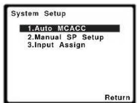
Using the System Setup menu .....41
Manual speaker setup....41
Speaker Setting 42
Crossover Network 43
Channel Level 43
Speaker Distance 44
The Input Assign menu 44
07 Using the MULTI-ZONE feature
MULTI-ZONE listening 46
Making MULTI-ZONE connections ..... 46
Using the MULTI-ZONE controls ..... 47
08 Using the tuner
Listening to the radio....48
Improving FM stereo sound 48
Saving station presets 48
Listening to station presets. 49
Naming preset stations....49
09 Making recordings
Making an audio or a video recording ..... 50
10 Controlling the rest of your system
Setting the remote to control other components 51
Selecting preset codes directly ..... 51
Clearing all the remote control settings.....51
Controls for TVs. 52
Controls for other components ..... 53
Preset Code List 55
11 Other connections
Connecting an iPod....58
Connecting your iPod to the receiver ..... 58
iPod playback 59
Watching photos and video content ..... 60
About iPod 60
Connecting a USB device 60
Connecting your USB device to the receiver....61
Basic playback controls 61
Compressed audio compatibility. 62
Using SIRIUS Radio 62
Connecting your SiriusConnect™ Tuner 63
Listening to SIRIUS Radio....63
Saving channel presets....64
Using the SIRIUS Menu 64
Connecting an IR receiver 64
Troubleshooting 65
HDMI 67
Important information regarding the
HDMI connection 67
iPod messages 68
USB messages 68
SIRIUS radio messages 68
Resetting the main unit....69
Specifications 69
Power cord caution 70
Cleaning the unit....70
Manufactured under license from Dolby Laboratories. Dolby, Pro Logic, Surround EX and the double-D symbol are trademarks of Dolby Laboratories.
Manufactured under license under U.S. Patent #'s: 5,451,942; 5,956,674; 5,974,380; 5,978,762; 6,226,616; 6,487,535 & other U.S. and worldwide patents issued & pending. DTS is a registered trademark and the DTS logos, Symbol, DTS-HD and DTS-HD Master Audio are trademarks of DTS, Inc. © 1996-2007 DTS, Inc. All Rights Reserved.
Chapter 1:
Before you start
Checking what's in the box
Please check that you've received the following supplied accessories:
- Setup microphone
- Remote control
• Dry cell batteries (AAA size IEC R03) x2
- AM loop antenna
• FM wire antenna
- iPod cable
• These operating instructions
Loading the batteries
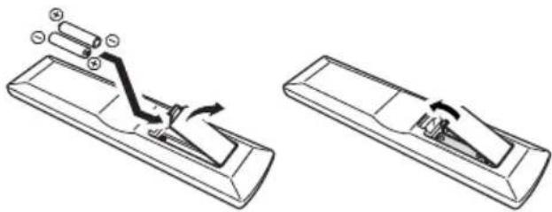
natural_image
Diagram showing two views of a remote control device with arrows indicating motion (no text or symbols)

Caution
Incorrect use of batteries may result in such hazards as leakage and bursting. Observe the following precautions:
- Never use new and old batteries together.
- Insert the plus and minus sides of the batteries properly according to the marks in the battery case.
- Batteries with the same shape may have different voltages. Do not use different batteries together.
- When disposing of used batteries, please comply with governmental regulations or environmental public instruction's rules that apply in your country or area.
- Do not use or store batteries in direct sunlight or other excessively hot place, such as inside a car or near a heater. This can cause batteries to leak, overheat, explode or catch fire. It can also reduce the life or performance of batteries.
(Symbol examples for batteries)
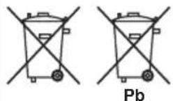
These symbols are only valid in the European Union.
K058c_A1_En
Installing the receiver
- When installing this unit, make sure to put it on a level and stable surface.
Don't install it on the following places:
-on a color TV (the screen may distort)
- near a cassette deck (or close to a device that gives off a magnetic field). This may interfere with the sound.
- in direct sunlight
- in damp or wet areas
- in extremely hot or cold areas
– in places where there is vibration or other movement
- in places that are very dusty
– in places that have hot fumes or oils (such as a kitchen)
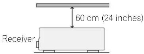
Ventilation
When installing this unit, make sure to leave space around the unit for ventilation to improve heat dispersal (at least 60 cm (24 in.) at the top). If not enough space is provided between the unit and walls or other equipment, heat will build up inside, interfering with performance and/or causing malfunctions.
Before you start
Slot and openings in the cabinet are provided for ventilation and to protect the equipment from overheating. To prevent fire hazard, do not place anything directly on top of the unit, make sure the openings are never blocked or covered with items (such as newspapers, table-cloths and curtains), and do not operate the equipment on thick carpet or a bed.
Chapter 2:
5 minute guide
Introduction to home theater
Home theater refers to the use of multiple audio tracks to create a surround sound effect, making you feel like you're in the middle of the action or concert. The surround sound you get from a home theater system depends not only on your speaker setup, but also on the source and the sound settings of the receiver.
This receiver will automatically decode multichannel Dolby Digital, DTS, or Dolby Surround sources according to your speaker setup. In most cases, you won't have to make changes for realistic surround sound, but other possibilities (like listening to a CD with multichannel surround sound) are explained in Listening to your system on page 33.
Listening to Surround Sound
With the following quick setup guide, you should have your system hooked up for surround sound in no time at all. In most cases, you can simply leave the receiver in the default settings.
- Be sure to complete all connections before connecting to an AC power source.
1 Connect your TV and Blu-ray Disc player or DVD player.
See Connecting a TV and Blu-ray Disc player or DVD player on page 14 to do this. For surround sound, you'll want to hook up using a digital connection from the BD/DVD player to the receiver.
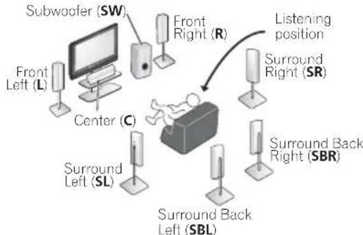
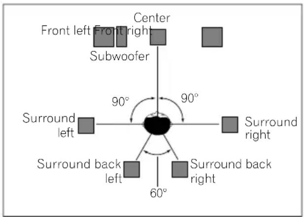
2 Connect your speakers and place them for optimal surround sound.
See Connecting the speakers on page 22.
Where you place the speakers will have a big effect on the sound. Place your speakers as shown below for the best surround sound effect. Also see Placing the speakers on page 24 for more on this.
flowchart
graph TD
    A["Subwoofer (SW)"] --> B["Central Display"]
    C["Front Left (L)"] --> B
    D["Center (C)"] --> B
    E["Surround Left (SL)"] --> F["Surround Back Left (SBL)"]
    G["Front Right (R)"] --> H["Surround Right (SR)"]
    I["Surround Back Right (SBR)"] --> H
    J["Listening position"] --> H

Important
- To connect the surround back speakers, an additional amplifier is required. Connect the additional amplifier to the PRE OUT SURROUND BACK outputs of this unit and connect the surround back speakers to the additional amplifier. For details, see Use the PRE OUT outputs to connect the surround back speakers on page 23.
3 Plug in and switch on the receiver, followed by your BD/DVD player, subwoofer and TV.
Make sure you've set the video input on your TV to this receiver. Check the manual that came with the TV if you don't know how to do this.
4 Use the on-screen automatic MCACC setup to set up your system.
See Automatically setting up for surround sound (MCACC) on page 9 for more on this.
5 Play a BD/DVD, and adjust the volume. Make sure that BD/DVD is showing in the receiver's display. If it isn't, press BD on the remote to set the receiver to the BD/DVD input. ^1 There are several other sound options you can select. See Listening to your system on page 33 for more on this. ^2
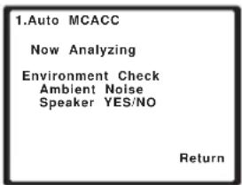
Automatically setting up for surround sound (MCACC)
The Auto Multi-Channel Acoustic Calibration (MCACC) setup measures the acoustic characteristics of your listening area, taking into account ambient noise, speaker size and distance, and tests for both channel delay and channel level. After you have set up the microphone provided with your system, the receiver uses the information from a series of test tones to optimize the speaker settings and equalization for your particular room.

Important
- The Auto MCACC Setup will overwrite any existing speaker settings you've made.
- Before using the Auto MCACC Setup, the iPod USB function should not be selected as an input source.

Caution
- The test tones used in the Auto MCACC Setup are output at high volume.
1 Switch on the receiver and your TV.
2 Connect the microphone to the MCACC SETUP MIC jack on the front panel.
Make sure there are no obstacles between the speakers and the microphone.
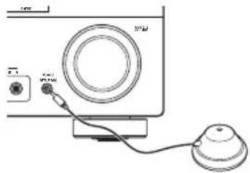
If you have a tripod, use it to place the microphone so that it's about ear level at your normal listening position. Otherwise, place the microphone at ear level using a table or a chair.
An on-screen display (OSD) appears on your TV. Use ↑/↓/←/→ and ENTER on the remote control to navigate through the screens and select menu items. Press RETURN to exit the current menu.
- Press SETUP at any time to exit the System Setup menu. ^3
Try to be as quiet as possible after pressing ENTER. The system outputs a series of test tones to establish the ambient noise level.

Note
1 You may need to set your BD/DVD player to output Dolby Digital, DTS and 88.2 kHz/96 kHz PCM (2 channel) audio (see your BD/DVD player's manual for more on this).
2 Depending on your BD/DVD player or source disc, you may only get 2 channel sound. In this case, the listening mode must be set to STANDARD (see Listening in surround sound on page 33 if you need to do this) if you want multichannel surround sound.
3 • The screensaver automatically starts after three minutes of inactivity. If you cancel the Auto MCACC Setup at any time, the receiver automatically exits and no settings will be made.
- The OSD will not appear if you have connected using the HDMI output to your TV. Use component or composite connections for system setup.
4 MIC IN blinks when the microphone is not connected to MCACC SETUP MIC.
5 minute guide
5 Follow the instructions on-screen.
- Make sure the microphone is connected.
- Make sure the subwoofer is on and the volume is turned up.
• See below for notes regarding background noise and other possible interference.
6 Wait for the test tones to finish.
A progress report is displayed on-screen while the receiver outputs test tones to determine the speakers present in your setup. Try to be as quiet as possible while it's doing this.
- For correct speaker settings, do not adjust the volume during the test tones.
7 Confirm the speaker configuration.
The configuration shown on-screen should reflect the actual speakers you have.
- With error messages (such as Too much ambient noise) select RETRY after checking for ambient noise (see Other problems when using the Auto MCACC Setup on page 11).
![1.Auto MCACC Check! Front [ YES ] Center [ YES ] Surr [ YES ] Surr. Back [ YESx2 ] Subwoofer [ YES ] 10:Next OK Return](/content/2026/02/379021/images/4ad1aceaaabf2920becda71a867b1f0b4f5fbe04673558551bc11826f2837a23.jpg)
If the speaker configuration displayed isn't correct, use / to select the speaker and / to change the setting. When you're finished, go to the next step.
If you see an error message (ERR) in the right side column, there may be a problem with the speaker connection. If selecting RETRY doesn't fix the problem, turn off the power and check the speaker connections.
8 Make sure 'OK' is selected, then press ENTER.
If the screen in step 7 is left untouched for 10 seconds and the ENTER button is not pressed in step 8, the Auto MCACC setup will start automatically as shown below.
A progress report is displayed on-screen while the receiver outputs more test tones to determine the optimum receiver settings for channel level, speaker distance, and Acoustic Calibration EQ.
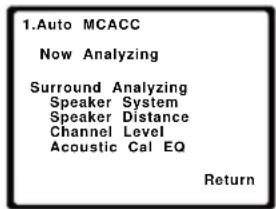
Again, try to be as quiet as possible while this is happening. It may take 1 to 3 minutes.
The settings made in the Auto MCACC Setup should give you excellent surround sound from your system, but it is also possible to adjust these settings manually using the System Setup menu (starting on page 41). ^1

Note
- Depending on the characteristics of your room, sometimes identical speakers with cone sizes of around 12 cm (5 inches) will end up with different size settings. You can correct the setting manually using the Speaker Setting on page 42.
- The subwoofer distance setting may be farther than the actual distance from the listening position. This setting should be accurate (taking delay and room characteristics into account) and generally does not need to be changed.
Other problems when using the Auto MCACC Setup
If the room environment is not optimal for the Auto MCACC Setup (too much background noise, echo off the walls, obstacles blocking the speakers from the microphone) the final settings may be incorrect. Check for household appliances (air conditioner, fridge, fan, etc.), that may be affecting the environment and switch them off if necessary. If there are any instructions showing in the front panel display, please follow them.
- Some older TVs may interfere with the operation of the microphone. If this seems to be happening, switch off the TV when doing the Auto MCACC Setup.
Better sound using Phase Control
This receiver's Phase Control feature uses phase correction measures to make sure your sound source arrives at the listening position in phase, preventing unwanted distortion and/or coloring of the sound (see illustration below).
During multichannel playback, LFE (Low-Frequency Effects) signals as well as low-frequency signals in each channel are assigned to the subwoofer or other the subwoofer and the most appropriate speaker. At least in theory, however, this type of processing involves a group delay that varies with frequency, resulting in phase distortion where the low-frequency sound is delayed or muffled by the conflict with other channels.
With the Phase Control mode switched on, this receiver can reproduce powerful bass sound without deteriorating the quality of the original sound (see illustration below).
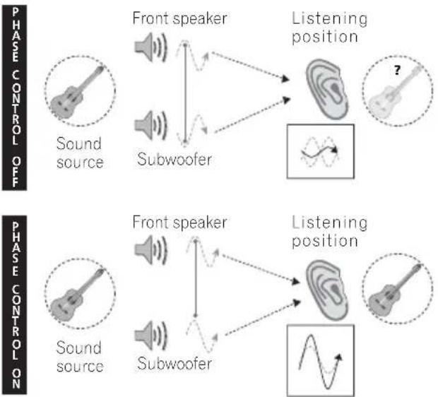
Phase Control technology provides coherent sound reproduction through the use of phase matching ^1 for an optimal sound image at your listening position. The default setting is on and we recommend leaving Phase Control switched on for all sound sources.
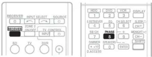
- Press RECEIVER, then press PHASE to switch on phase correction.

Note
1 Phase matching is a very important factor in achieving proper sound reproduction. If two waveforms are 'in phase', they crest and trough together, resulting in increased amplitude, clarity and presence of the sound signal. If a crest of a wave meets a trough (as shown in the upper section of the diagram above) then the sound will be 'out of phase' and an unreliable sound image will be produced.
- If your subwoofer has a phase control switch, set it to the plus (+) sign (or 0^ ). However, the effect you can actually feel when PHASE CONTROL is set to ON on this receiver depends on the type of your subwoofer. Set your subwoofer to maximize the effect. It is also recommended you try changing the orientation or the place of your subwoofer.
- Set the built-in lowpass filter switch of your subwoofer to OFF. If this cannot be done on your subwoofer, set the cutoff frequency to a higher value.
- If the speaker distance is not properly set, you may not have a maximized PHASE CONTROL effect.
- The PHASE CONTROL mode cannot be set to ON in the following cases:
- When the PURE DIRECT mode is switched on.
- When the MULTI IN input is selected.
Chapter 3:
Connecting up
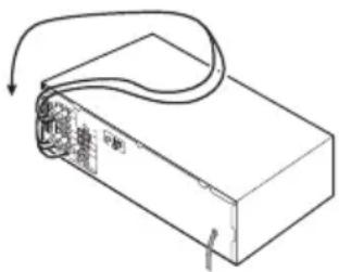
Making cable connections
Make sure not to bend the cables over the top of this unit (as shown in the illustration). If this happens, the magnetic field produced by the transformers in this unit may cause a humming noise from the speakers.
natural_image
Line drawing of a rectangular electronic device with a curved cable and internal components, no text or symbols present.

Important
- Before making or changing connections, switch off the power and disconnect the power cord from the AC outlet.
- Before unplugging the power cord, switch the power into standby.
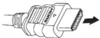
HDMI cables
The HDMI cables transfers uncompressed digital video, as well as almost every kind of digital audio that the connected component is compatible with, including DVD-Video, DVD-Audio, Dolby Digital Plus, Dolby TrueHD, DTS-HD Master Audio (see below for limitations), Video CD/Super VCD, CD, SACD (DSD 2 ch only) and 192 kHz/8 ch (Max. number of channel inputs) PCM. ^1
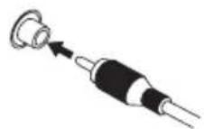
Be careful to connect the terminal in the proper direction.
About HDMI
HDMI (High Definition Multimedia Interface) supports both video and audio on a single digital connection for use with DVD players, DTV, set-top boxes, and other AV devices. HDMI was developed to provide the technologies of High Bandwidth Digital Content Protection (HDCP) as well as Digital Visual Interface (DVI) in one specification. HDCP is used to protect digital content transmitted and received by DVI-compliant displays.
HDMI has the capability to support standard, enhanced, or high-definition video plus standard to multi-channel surround-sound audio. HDMI features include uncompressed digital video, a bandwidth of up to 2.2 gigabytes per second (with HDTV signals), one connector (instead of several cables and connectors), and communication between the AV source and AV devices such as DTVs.
This receiver is also compatible with the DeepColor and x.v.Color feature (x.v.Color is trademarks of Sony Corporation).
HDMI, the HDMI logo and High-Definition Multimedia Interface are trademarks or registered trademarks of HDMI Licensing, LLC.
natural_image
Technical line drawing of a mechanical connector with threaded end and arrow indicating direction (no text or symbols)
HDMI cable

Note
1 • Set the HDMI parameter in Setting the Audio options on page 38 to THRU (THROUGH) and set the input signal in Choosing the input signal on page 40 to HDMI, if you want to hear HDMI audio output from your TV or flat panel TV (no sound will be heard from this receiver).
- If the video signal does not appear on your TV or flat panel TV, try adjusting the resolution settings on your component or display. Note that some components (such as video game units) have resolutions that may not be displayed. In this case, use a (analog) composite connection.
- The signals input from the analog (composite and component) video inputs of this unit will not be output from the HDMI OUT.
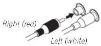
Analog audio cables
Use stereo RCA phono cables to connect analog audio components. These cables are typically red and white, and you should connect the red plugs to R (right) terminals and white plugs to L (left) terminals.
Analog audio cables
Digital audio cables
Commercially available coaxial digital audio cables or optical cables should be used to connect digital components to this receiver. ^1
Coaxial digital audio cable
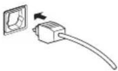
Optical cable
Video cables
Standard RCA video cables
These cables are the most common type of video connection and are used to connect to the composite video terminals. The yellow plugs distinguish them from cables for audio.
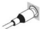
Standard RCA video cable
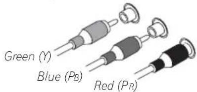
Component video cables
Use component video cables to get the best possible color reproduction of your video source. The color signal of the TV is divided into the luminance (Y) signal and the color (PB and PR) signals and then output. In this way, interference between the signals is avoided.
Component video cables
About video outputs connection
This receiver is not loaded with a video converter. When you use component video cables or HDMI cables for connecting to the input device, the same cables should be used for connecting to the TV.

Note
1 • When connecting optical cables, be careful when inserting the plug not to damage the shutter protecting the optical socket.
- When storing optical cable, coil loosely. The cable may be damaged if bent around sharp corners.
- You can also use a standard RCA video cable for coaxial digital connections.
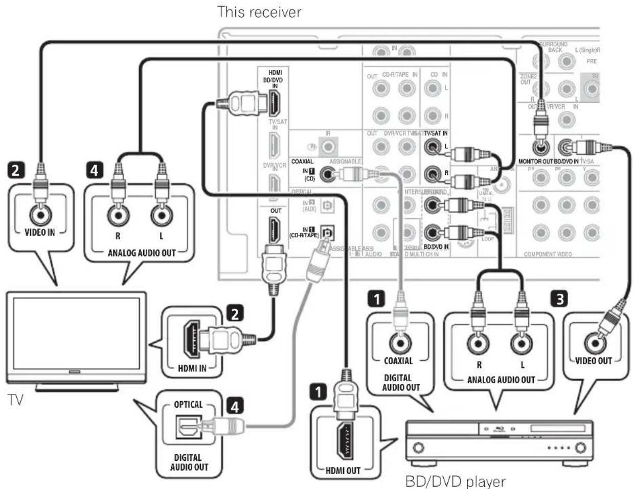
Connecting a TV and Blu-ray Disc player or DVD player
This page shows you how to connect your BD/DVD player and TV to the receiver.
flowchart
graph TD
    A["TV"] --> B["2: VIDEO IN"]
    A --> C["4: R L ANALOG AUDIO OUT"]
    C --> D["2: HDMI IN"]
    C --> E["4: DIGITAL AUDIO OUT"]
    D --> F["1: HDMI OUT"]
    D --> G["1: COAXIAL DIGITAL AUDIO OUT"]
    G --> H["3: R L ANALOG AUDIO OUT"]
    H --> I["3: VIDEO OUT"]
    I --> J["1: BD/DVD player"]
    style A fill:#f9f,stroke:#333
    style J fill:#ccf,stroke:#333
Use an HDMI cable for the connection. If an HDMI output is not on your DVD player, use a digital audio cable to connect the coaxial or optional output and this unit. ^1
If an HDMI input is not on your TV, connect the MONITOR OUT video jack on this receiver to a video input on your TV.
Use a standard RCA video cable to connect to the composite video jack. ^3

Note
1 In this case, you'll need to tell the receiver which digital input you connected the player to (see Choosing the input signal on page 40).
2 • When you use an HDMI cable for connection in steps 1 and 2, you can enjoy the home theater in multichannel playback without following steps 3 and 4.
- The OSD will not appear if you have connected using the HDMI output to your TV. Use component or composite connections for system setup.
3 See Using the component video jacks on page 19 if you want to use the component video outputs to connect this receiver to your TV.
Use a standard RCA video cable ^2 and a stereo RCA phono cable for the connection.
- If your BD/DVD player has multichannel analog outputs, see Connecting the multichannel analog outputs below for how to connect it.
This will allow you to play the sound from the TV's built-in tuner. Use a stereo RCA phono cable to do this.
- If your TV has a built-in digital decoder, you can also connect an optical digital audio output from your TV to the DIGITAL OPTICAL IN 2 (AUX) input on this receiver. Use an optical cable for the connection. ^3
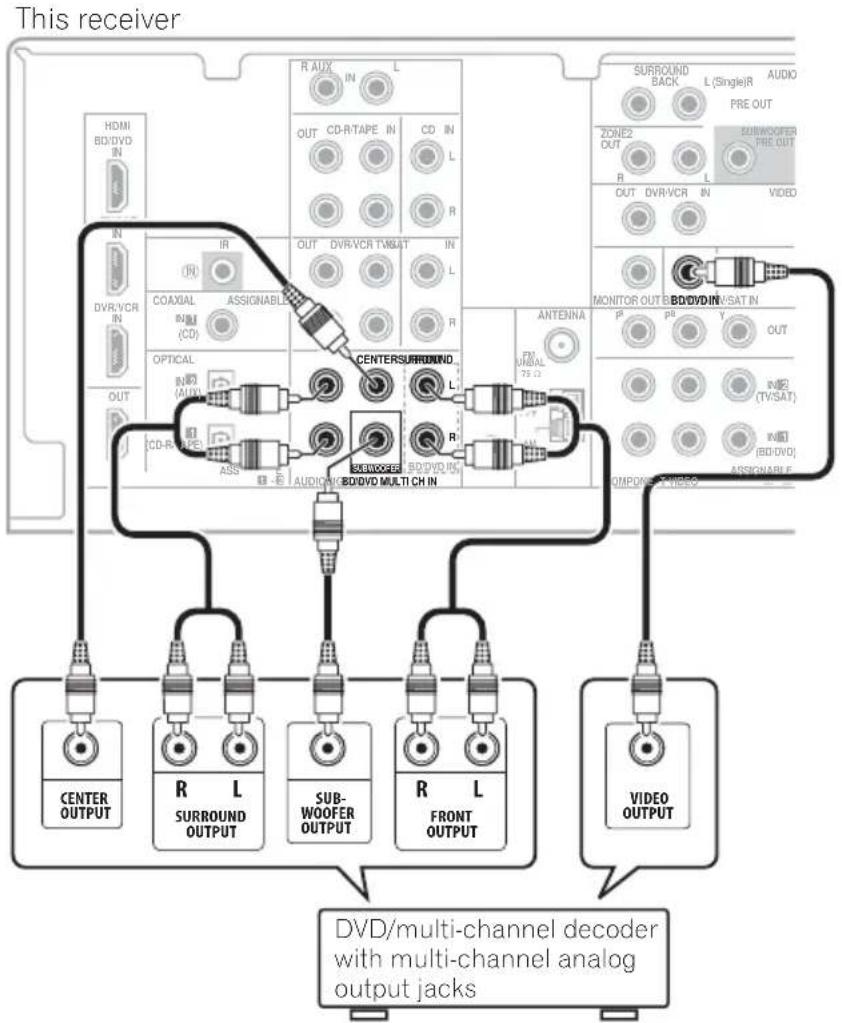
Connecting the multichannel analog outputs
For DVD Audio and SACD playback, your BD/DVD player may have 5.1 channel analog outputs. In this case, you can connect them to the multichannel analog outputs to the multichannel inputs of this receiver as shown below. ^4
flowchart
graph TD
    A["This receiver"] --> B["HD/BI/DVD IN"]
    A --> C["IN"]
    A --> D["DVR/VCR IN"]
    A --> E["OUT"]
    A --> F["CD-R/TAPE IN"]
    A --> G["ASSIGNABLE"]
    A --> H["COAXIAL IN (CD)"]
    A --> I["OPTICAL IN (AUX)"]
    A --> J["CD-R/TAPE"]
    A --> K["AUDI/OFFR/BD/DVD MULTI CH IN"]
    A --> L["R AUX IN"]
    A --> M["L"]
    A --> N["OUT"]
    A --> O["CD/R/TAPE IN"]
    A --> P["L"]
    A --> Q["R"]
    A --> R["OUT"]
    A --> S["DVR/VCR TV/SAT IN"]
    A --> T["IN"]
    A --> U["L"]
    A --> V["R"]
    A --> W["L"]
    A --> X["ANTENNA FM VIN BAL PS 12"]
    A --> Y["MEMOR OUT B/BO/DVD/INSAT IN"]
    A --> Z["P PS Y OUT"]
    A --> AA["VDD/TV/SAT IN"]
    A --> AB["R/BO/DVD ASSIGNABLE"]
    A --> AC["CENTER OUTPUT"]
    A --> AD["R L SURROUND OUTPUT"]
    A --> AE["SUB-WOOFER OUTPUT"]
    A --> AF["R L FRONT OUTPUT"]
    A --> AG["VIDEO OUTPUT"]
    A --> AH["DVD/multi-channel decoder with multi-channel analog output jacks"]

Note
1 This connection will allow you to make analog recordings from your BD/DVD player.
2 If your player also has a component video output, you can connect this too. See Using the component video jacks on page 19 for more on this.
3 In this case, you'll need to tell the receiver which digital input you connected the TV to (see Choosing the input signal on page 40).
4 • The multichannel input can only be used when MULTI IN is selected (see page 40).
- You can assign COMPONENT VIDEO IN 1 or IN 2 to the multi channel input. (For more on this, see The Input Assign menu on page 44.)
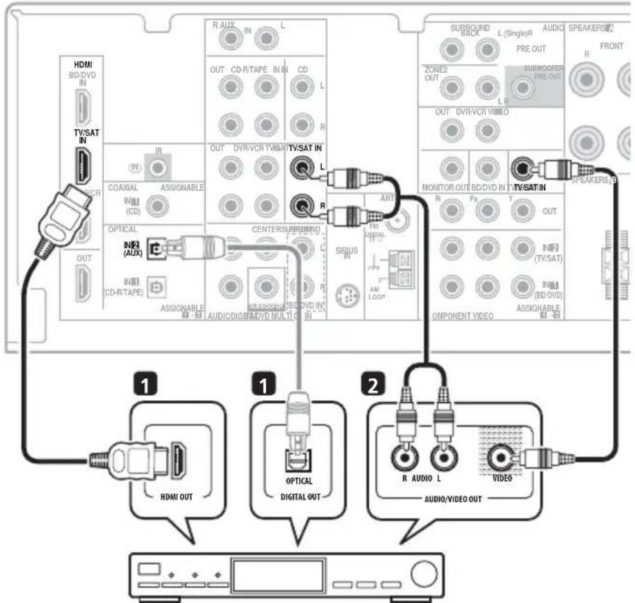
Connecting a satellite receiver or other digital set-top box
Satellite and cable receivers, and terrestrial digital TV tuners are all examples of so-called 'set-top boxes'.
This receiver
STB
1 If your set-top box has an HDMI output, connect it to an HDMI TV/SAT IN on this reciever.
If your set-top box does not have an HDMI output but a digital output, connect it to a digital input on this receiver.
The example shows an optical connection to the DIGITAL OPTICAL IN 2 (AUX) input. ^1
Use a stereo RCA phono cable for the audio connection and a standard RCA video cable for the video connection. ^3

Note
1 In this case, you'll need to tell the receiver which input you connected the set-top box to (see Choosing the input signal on page 40).
2 If you've already connected your TV to the TV/SAT inputs, simply choose another input. However, to receive a signal, you'll need to press the input select button for the input you connected the set-top box to.
3 See Using the component video jacks on page 19 if your set-top box also has a component video output.
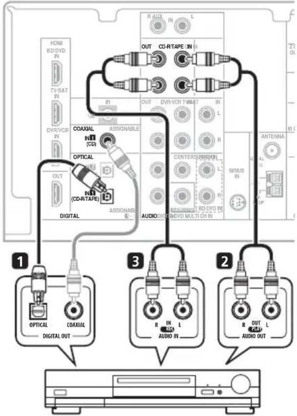
Connecting other audio components
The number and kind of connections depends on the kind of component you're connecting. ^1 Follow the steps below to connect a CD-R, MD, DAT, tape recorder or other audio component.
1 If your component has a digital output, connect this to a digital input on the receiver as shown.
The example shows an optical connection to the DIGITAL OPTICAL IN 1 (CD-R/TAPE) input.
2 If necessary, connect the analog audio outputs of the component to a set of spare audio inputs on this receiver.
You'll need to make this connection for components without a digital output, or if you want to record from a digital component. Use a stereo RCA phono cable as shown.
3 If you're connecting a recorder, connect the analog audio outputs to the analog audio inputs on the recorder.
The example shows an analog connection to the CD-R/TAPE analog output jack using a stereo RCA phono cable.
This receiver
CD-R, MD, DAT, Tape recorder, etc.

Note
1 Note that you must connect digital components to analog audio jacks if you want to record to/from digital components (like an MD) to/from analog components.
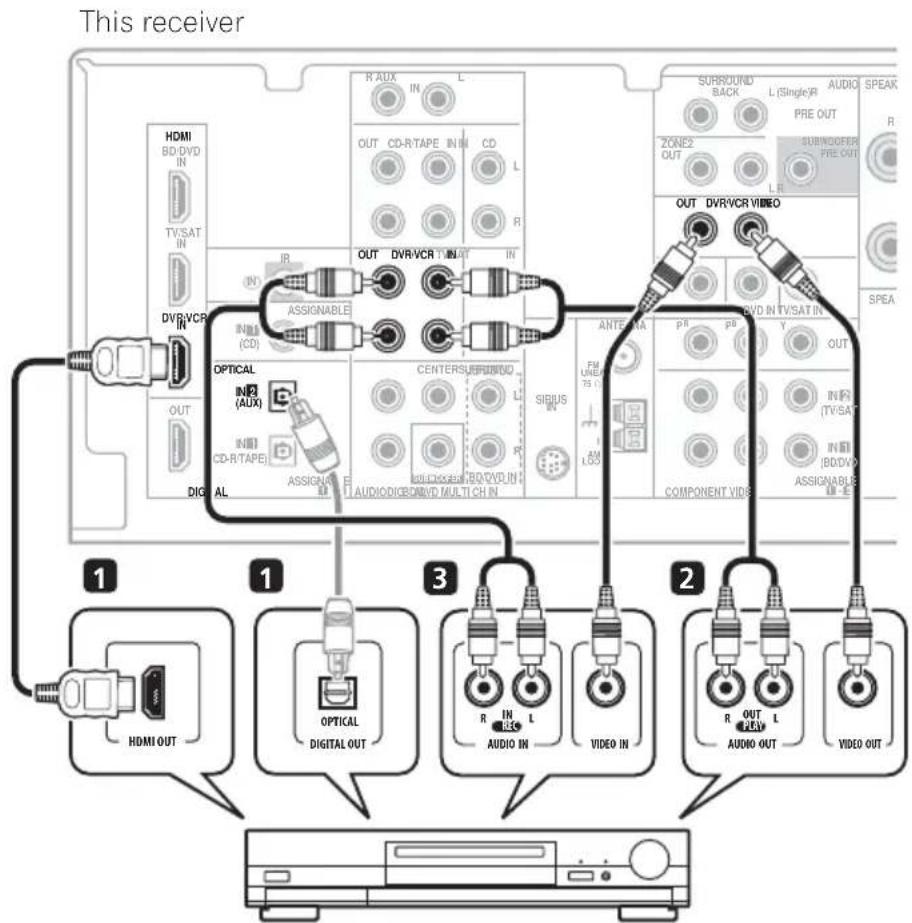
Connecting an HDD/DVD recorder, VCR and other video sources
This receiver has audio/video inputs and outputs suitable for connecting analog or digital video recorders, including VCRs and HDD/DVD recorders.
flowchart
graph TD
    A["This receiver"] --> B["1: HDMI OUT"]
    A --> C["1: OPTICAL DIGITAL OUT"]
    A --> D["2: R IN L AUDIO IN VIDEO IN"]
    A --> E["3: R IN L AUDIO IN VIDEO IN"]
    A --> F["4: R OUT L AUDIO OUT VIDEO OUT"]
    B --> G["1: HDMI OUT"]
    C --> H["2: OPTICAL DIGITAL OUT"]
    D --> I["3: R IN L AUDIO IN VIDEO IN"]
    E --> J["4: R OUT L AUDIO OUT VIDEO OUT"]
DVR, VCR, LD player, etc.
1 If your video component has an HDMI output, connect it to an HDMI DVR/VCR IN on this receiver.
If your video component does not have an HDMI audio output but a digital audio output, connect it to a digital input on this receiver.
The example shows a recorder connected to the DIGITAL OPTICAL IN 2 (AUX) input. ^1
Use a stereo RCA phono cable for the audio connection and a standard RCA video cable for the video connection. ^2
Use a stereo RCA phono cable for the audio connection and a standard RCA video cable for the video connection.

Note
1 In this case, you'll need to tell the receiver which digital input you connected the component to (see Choosing the input signal on page 40).
2 If your video component also has a component video output, you can connect this too. See Using the component video jacks on page 19 for more on this.
Using the component video jacks
Component video should deliver superior picture quality when compared to composite video. A further advantage (if your source and TV are both compatible) is progressive-scan video, which delivers a very stable, flicker-free picture. See the manuals that came with your TV and source component to check whether they are compatible with progressive-scan video.
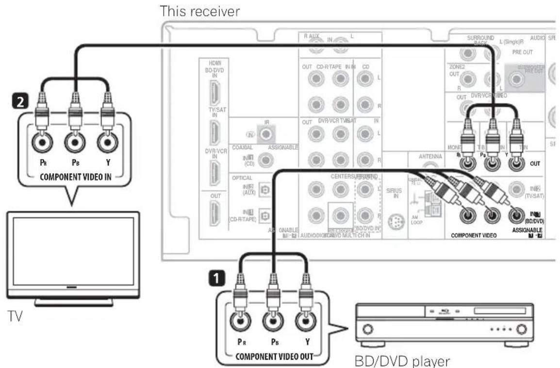

Important
- If you connect any source component to the receiver using a component video input, you must also have your TV connected to this receiver's COMPONENT VIDEO OUT jacks.
Use a three-way component video cable for the connection.
This only needs to be done if you didn't connect according to the following defaults:
- COMPONENT VIDEO IN 1 – BD/DVD
• COMPONENT VIDEO IN 2 – TV/SAT
See The Input Assign menu on page 44 for more on this.
Use a three-way component video cable.
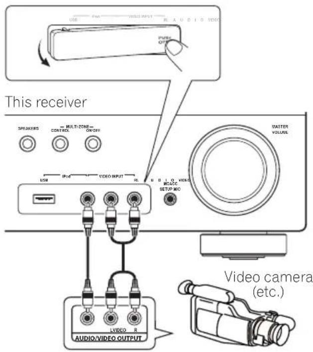
Connecting to the front panel video terminal
Front video connections are accessed via the front panel using the INPUT SELECTOR or VIDEO button on the remote control. There are standard audio/video jacks. Hook them up the same way you made the rear panel connections.
- Push down on the PUSH OPEN tab to access the front video connections.
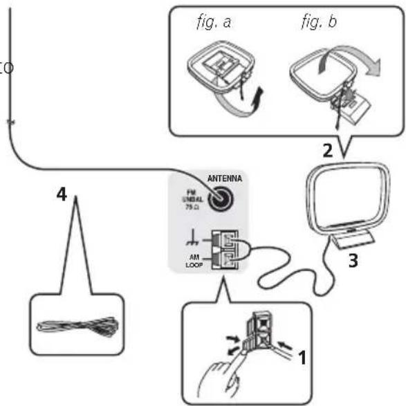
Connecting antennas
Connect the AM loop antenna and the FM wire antenna as shown below. To improve reception and sound quality, connect external antennas (see Using external antennas on page 21).
flowchart
graph TD
    A["Terminal"] --> B["Wireless Cable"]
    B --> C{Switch}
    C -->|1| D["Monitor"]
    C -->|2| E["Antenna"]
    E --> F["Switch"]
    F --> G["Wireless Cable"]
    style A fill:#f9f,stroke:#333
    style B fill:#ccf,stroke:#333
    style C fill:#cfc,stroke:#333
    style D fill:#fcc,stroke:#333
    style E fill:#cff,stroke:#333
    style F fill:#ffc,stroke:#333
    style G fill:#fcc,stroke:#333
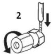
1 Push open the tabs, then insert one wire fully into each terminal, then release the tabs to secure the AM antenna wires.
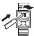
2 Fix the AM loop antenna to the attached stand.
To fix the stand to the antenna, bend in the direction indicated by the arrow (fig. a) then clip the loop onto the stand (fig. b).
3 Place the AM antenna on a flat surface and in a direction giving the best reception.
4 Connect the FM wire antenna in the same way as the AM loop antenna.
For best results, extend the FM antenna fully and fix to a wall or door frame. Don't drape loosely or leave coiled up.
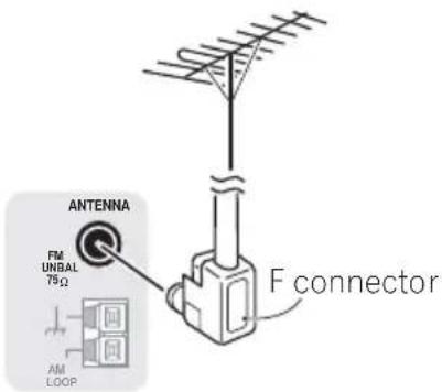
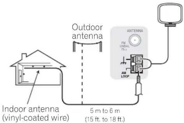
Using external antennas
To improve FM reception
Use an F connector (not supplied) to connect an external FM antenna.
To improve AM reception
Connect a 5 m to 6 m (15 ft. to 18 ft.) length of vinyl-coated wire to the AM antenna terminal without disconnecting the supplied AM loop antenna.
For the best possible reception, suspend horizontally outdoors.
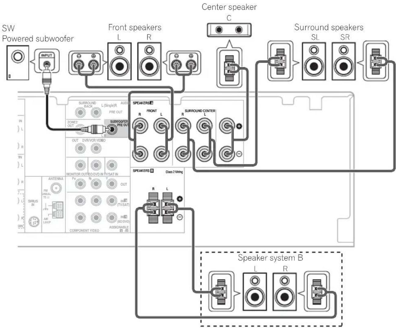
Connecting the speakers
A complete setup of six speakers (including the subwoofer) is shown here but everyone's home setup will vary. Simply connect the speakers you have in the manner shown below. The receiver will work with just two stereo speakers (the front speakers in the diagram) but using at least three speakers is recommended, and a complete setup is best for surround sound. If you're not using a subwoofer, change the front speaker setting (see Speaker Setting on page 42) to LARGE.
Make sure you connect the speaker on the right to the right terminal and the speaker on the left to the left terminal.
You can use the speakers connected to the B speaker terminals to listen to stereo playback in another room. Make sure to review Placing the speakers on page 24 when placing the speakers in another room. See Switching the speaker system on page 25 for the listening options with this setup.
You can use speakers with a normal impedance between 6 Ω and 16 Ω.
However, note that only the front speakers are set to a value between 12 Ω and 16 Ω if you select SP▶AB in Switching the speaker system on page 25.
Be sure to complete all connections before connecting this unit to the AC power source.
flowchart
graph TD
    A["SW Powered subwoofer"] --> B["INPUT"]
    B --> C["FRONT speakers L R"]
    C --> D["Center speaker C"]
    D --> E["Surround speakers SL SR"]
    C --> F["SURROUND BACK L(Single/R) PRE OUT"]
    F --> G["SURROUND CENTER R FRONT L"]
    G --> H["SURROUND CENTER L"]
    H --> I["SURROUND CENTER R"]
    I --> J["SURROUND CENTER L"]
    J --> K["SURROUND CENTER R"]
    K --> L["SURROUND CENTER L"]
    L --> M["SURROUND CENTER R"]
    M --> N["SURROUND CENTER L"]
    N --> O["SURROUND CENTER R"]
    O --> P["SURROUND CENTER L"]
    P --> Q["SURROUND CENTER R"]
    Q --> R["SURROUND CENTER L"]
    R --> S["SURROUND CENTER R"]
    S --> T["SURROUND CENTER L"]
    T --> U["SURROUND CENTER R"]
    U --> V["SURROUND CENTER L"]
    V --> W["SURROUND CENTER R"]
    W --> X["SURROUND CENTER L"]
    X --> Y["SURROUND CENTER R"]
    Y --> Z["SURROUND CENTER L"]
    Z --> AA["SURROUND CENTER R"]
    AA --> AB["SURROUND CENTER L"]
    AB --> AC["SURROUND CENTER R"]
    AC --> AD["SURROUND CENTER L"]
    AD --> AE["SURROUND CENTER R"]
    AE --> AF["SURROUND CENTER L"]
    AF --> AG["SURROUND CENTER R"]
    AG --> AH["SURROUND CENTER L"]
    AH --> AI["SURROUND CENTER R"]
    AI --> AJ["SURROUND CENTER L"]
    AJ --> AK["SURROUND CENTER R"]
    AK --> AL["SURROUND CENTER L"]
    AL --> AM["SURROUND CENTER R"]
    AM --> AN["SURROUND CENTER L"]
    AN --> AO["SURROUND CENTER R"]
    AO --> AP["SURROUND CENTER L"]
    AP --> AQ["SURROUND CENTER R"]
    AQ --> AR["SURROUND CENTER L"]
    AR --> AS["SURROUND CENTER R"]
    AS --> AT["SURROUND CENTER L"]
    AT --> AU["SURROUND CENTER R"]
    AU --> AV["SURROUND CENTER L"]
Bare wire connections
A-Speaker terminals:
1 Twist exposed wire strands together.
2 Loosen terminal and insert exposed wire.
3 Tighten terminal.
1

10 mm (3/8 in.)

B-Speaker terminals:
1 Twist exposed wire strands together.
2 Push open the tabs and insert exposed wire.
3 Release the tabs.
1

10 mm (3/8 in.)
2
3


Caution
• These speaker terminals carry HAZARDOUS LIVE voltage. To prevent the risk of electric shock when connecting or disconnecting the speaker cables, disconnect the power cord before touching any uninsulated parts.
- Make sure that all the bare speaker wire is twisted together and inserted fully into the speaker terminal. If any of the bare speaker wire touches the back panel it may cause the power to cut off as a safety measure.
Use the PRE OUT outputs to connect the surround back speakers
Connect the PRE OUT outputs of the unit and additional amplifier to add a surround back speaker.
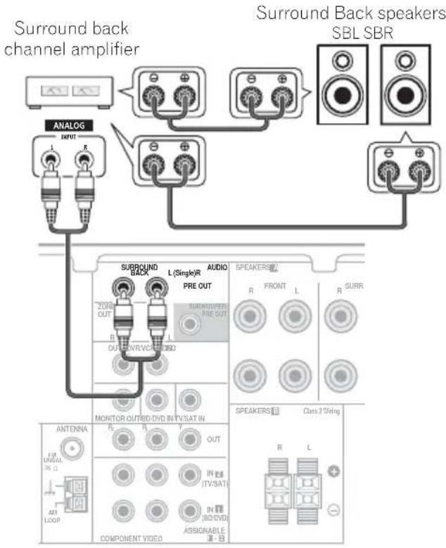
- You can use the additional amplifier on the surround back channel pre-outs for a single speaker as well. In this case plug the amplifier into the left (L (Single)) terminal only.
Placing the speakers
To achieve the best possible surround sound, install your speakers as shown below.
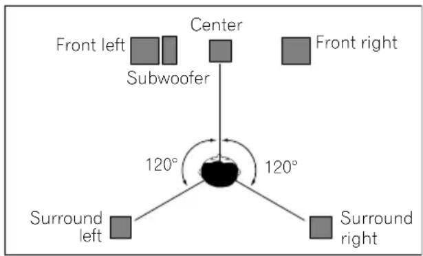
5.1 channel surround system:
6.1 channel surround system: ^1
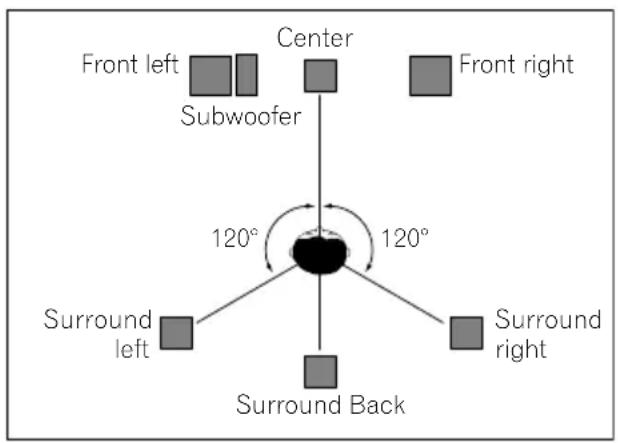
7.1 channel surround system: ^1
Where you put your speakers in the room has a big effect on the quality of the sound. The following guidelines should help you to get the best sound from your system.
- The subwoofer can be placed on the floor. Ideally, the other speakers should be at about ear-level when you're listening to them. Putting the speakers on the floor (except the subwoofer), or mounting them
- For the best stereo effect, place the front speakers 2 m to 3 m (6 ft. to 9 ft.) apart, at equal distance from the TV.
- When placing speakers near the TV, we recommend using magnetically shielded speakers to prevent possible interference, such as discoloration of the picture when the TV is switched on. If you do not have magnetically shielded speakers and notice discoloration of the TV picture, move the speakers farther away from the TV.
- If you're using a center speaker, place the front speakers at a wider angle. If not, place them at a narrower angle.
- Place the center speaker above or below the TV so that the sound of the center channel is localized at the TV screen. Also, make sure the center speaker does not cross the line formed by the leading edge of the front left and right speakers.
- It is best to angle the speakers towards the listening position. The angle depends on the size of the room. Use less of an angle for bigger rooms.
- Surround and surround back speakers should be positioned 60 cm to 90 cm (2 ft. to 3 ft.) higher than your ears and titled slight downward. Make sure the speakers don't face each other. For DVD-Audio, the speakers should be more directly behind the listener than for home theater playback.
Note
1 • This layout is available only when the additional amplifier is connected to the unit and the surround back speakers are connected to the amplifier. For details, see Use the PRE OUT outputs to connect the surround back speakers on page 23.
- When the Surround back channel processing is set to SB CH ON (see page 37) in this layout, sound is output from the surround back speakers even with the use of 5.1ch input signal.
Connecting up
- If the surround speakers cannot be set directly to the side of the listening position with a 7.1-channel system, the surround effect can be enhanced by turning off the UP Mix function (see Setting the Up Mix function on page 37).
- Try not to place the surround speakers farther away from the listening position than the front and center speakers. Doing so can weaken the surround sound effect.

Caution
- Make sure that all speakers are securely installed. This not only improves sound quality, but also reduces the risk of damage or injury resulting from speakers being knocked over or falling in the event of external shocks such as earthquakes.
Switching the speaker system
Three speaker system settings are possible using the SPEAKERS button.
- Use the SPEAKERS button on the front panel to select a speaker system setting. ^1

Press repeatedly to choose a speaker system option:
- SP▶A – Sound is output from the speakers connected to the A speaker terminals and SURROUND BACK PRE OUT
(multichannel playback is possible).
-
SP▶B – Sound is output from the two speakers connected to speaker system B (only stereo playback is possible).
-
SP▶AB – Sound is output from speaker system A, the two speakers in speaker system B, and the subwoofer.
Multichannel sources are downmixed only when the STEREO or A.L.C mode is selected for stereo output from speaker systems A and B. ^2
- SP▶ – No sound is output from the speakers but from the headphone jack.

Note
1 The subwoofer output depends on the settings you made in Speaker Setting on page 42. However, if SP▶B is selected above, no sound is heard from the subwoofer (the LFE channel is not downmixed).
2 You can use speakers with a normal impedance between 6 Ω and 16 Ω. However, be aware that only the front speakers are set to a value between 12 Ω and 16 Ω when you select SP▶AB.
Chapter 4:
Controls and displays
Front panel
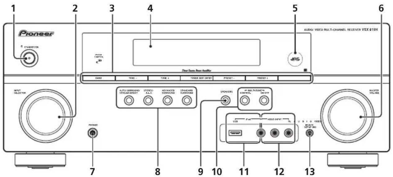
1 ⏻ STANDBY/ON
2 INPUT SELECTOR dial
Selects an input source.
3 Tuner control buttons
BAND
Switches between AM, FM ST (stereo) and FM MONO radio bands (page 48).
TUNE +/-
Used to find radio frequencies (page 48) and SIRIUS Radio channels (page 63).
TUNER EDIT
Use with TUNE +/-, PRESET +/- and ENTER to memorize and name stations for recall (page 48, 49). Used to preset the channel in SIRIUS Radio (page 63).
PRESET +/-
Use to select preset radio stations (page 49) and to select SIRIUS Radio channels (page 63).
4 Character display
See Display on page 28.
5 MCACC indicator
Lights when Acoustic Calibration EQ (page 36) is on (Acoustic Calibration EQ is automatically set to on after the Auto MCACC Setup (page 9)).
6 MASTER VOLUME dial
7 PHONES jack
Use to connect headphones (page 40).
8 Listening mode buttons
Switches between Auto surround mode (Auto playback on page 33) and Stream Direct playback. Stream Direct playback bypasses the tone controls for the most accurate reproduction of a source (page 36).
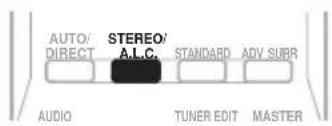
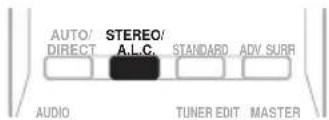
STEREO/A.L.C.
Switches between stereo playback, Auto level control stereo mode (page 35) and Front Stage Surround Advance modes (page 35).
Controls and displays
ADVANCED SURROUND
Switches between the various surround modes (page 34).
STANDARD SURROUND
Press for Standard decoding and to switch between the various ☐ Pro Logic II, ☐ Pro Logic IIx and NEO:6 options (page 33).
9 SPEAKERS
Use to change the speaker system (page 25).
10 MULTI ZONE controls
If you've made MULTI-ZONE connections (see MULTI-ZONE listening on page 46) use these controls to control the sub zone from the main zone (see Using the MULTI-ZONE controls on page 47).
11 iPod/USB terminal
Use to connect your Apple iPod or USB mass storage device as an audio source (page 58 and page 60).
See Connecting to the front panel video terminal on page 20.
13 MCACC SETUP MIC jack
Use to connect a microphone when performing Auto MCACC setup.
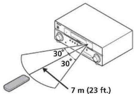
Operating range of remote control
The remote control may not work properly if:
- There are obstacles between the remote control and the receiver's remote sensor.
- Direct sunlight or fluorescent light is shining onto the remote sensor.
- The receiver is located near a device that is emitting infrared rays.
- The receiver is operated simultaneously with another infrared remote control unit.
Display
flowchart
graph TD
    A["PHASE AUTO"] --> B["ST TUNE ZONE SP→AB"]
    B --> C["PRESET MEM"]
    C --> D["DIR. HDMI"]
    D --> E["DTS HD ES 96/24 NEO:6"]
    D --> F["HD + EX PLIIx"]
    D --> G["ADVS. DIGITAL"]
    D --> H["10 11 12 13 14 15 16"]
    D --> I["9"]
    style A fill:#f9f,stroke:#333
    style B fill:#ccf,stroke:#333
    style C fill:#cfc,stroke:#333
    style D fill:#fcc,stroke:#333
    style E fill:#ffc,stroke:#333
    style F fill:#cfc,stroke:#333
    style G fill:#cfc,stroke:#333
    style H fill:#cfc,stroke:#333
    style I fill:#fcc,stroke:#333
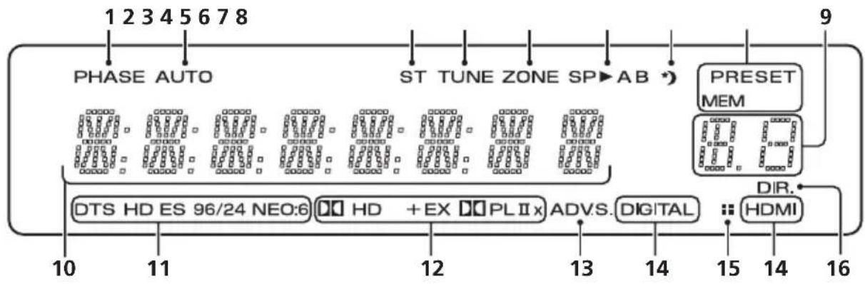
1 PHASE
Lights when the Phase Control is switched on (page 11).
2 AUTO
Lights when the Auto Surround feature is switched on (see Auto playback on page 33).
3 ST
Lights when a stereo FM broadcast is being received in auto stereo mode.
4 T U N E
Lights when a normal broadcast channel or SIRIUS channel is being received.
5 Z O N E
Lights when the MULTI-ZONE feature is active (page 46).
6 Speaker indicators
Lights to indicate the current speaker system, A and/or B (page 25).
7 Sleep timer indicator
Lights when the receiver is in sleep mode (page 32).
8 Tuner/SIRIUS preset indicators
PRESET
Shows when a preset radio station is registered or called.
MEM
Blinks when a radio station is registered.
Shows the preset number of the tuner or the input signal type, etc.
10 Character display
Displays various system infomation.
11 DTS indicators
DTS
Lights when a source with DTS encoded audio signals is detected.
HD
Lights when a source with DTS-EXPRESS or DTS-HD encoded audio signals is detected.
ES
Lights when a source with DTS-ES encoded audio signals is detected.
96/24
Lights when a source with DTS 96/24 encoded audio signals is detected.
NEO:6
When one of the NEO:6 modes of the receiver is on, this lights to indicate NEO:6 processing (page 33).
12 Dolby Digital indicators
D
Lights when a Dolby Digital encoded signal is detected.
Controls and displays
HD+
Lights when a source with Dolby Digital Plus encoded audio signals is detected.
HD
Lights when a source with Dolby TrueHD encoded audio signals is detected.
EX
Lights when a source with Dolby Digital EX encoded audio signals is detected.
DOPLIIx
Lights to indicate ☐ Pro Logic II / ☐ Pro Logic IIx decoding (see Listening in surround sound on page 33 for more on this).
13 ADV.S.
Lights when one of the Advanced Surround modes has been selected (see Using the Advanced surround effects on page 34 for more on this).
14 SIGNAL SELECT indicators
DIGITAL
Lights when a digital audio signal is selected.
Blinks when a digital audio signal is not selected.
HDMI
Lights when an HDMI signal is selected. Blinks when an HDMI signal is not selected.
15 UP MIX indicator
Lights when the UP MIX Setting is set to ON (see page 37). Also, lights when DIMMER is set to off.
16 DIR.
Lights when the DIRECT or PURE DIRECT mode is switched on (page 36).
Remote control
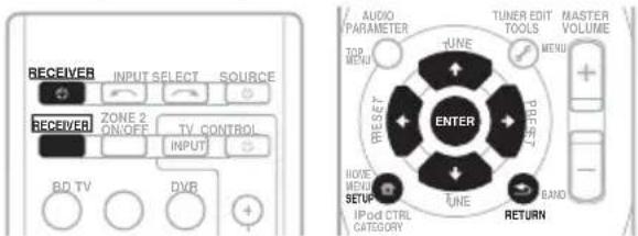
Use to select the input source.
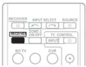
2 ⏻ RECEIVER
Switches the receiver between standby and on.
3 RECEIVER
Switches the remote to control the receiver (used to select the white commands above the number buttons (S.RETRIEVER, etc)). Also use this button to set up surround sound (page 41) or Audio parameters (page 38).
4 ZONE 2 ON/OFF
Switches zone 2 of the multi-zone function between on and off.
Press to select control of other components (see Controlling the rest of your system on page 51).
6 SIGNAL SEL
Use to select an input signal (page 40).
Press BD first to access:
Displays the disc menu of Blu-ray Discs.
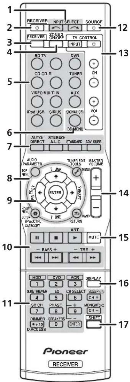
AUTO/DIRECT
Switches between Auto surround mode (Auto playback on page 33) and Stream Direct playback. Stream Direct playback bypasses the tone controls for the most accurate reproduction of a source (page 36).
STEREO/A.L.C.
Switches between stereo playback, Auto level control stereo mode (page 35) and Front Stage Surround Advance modes (page 35).
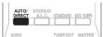
STANDARD
Press for Standard decoding and to switch between ☐☐ Pro Logic II options (page 33).
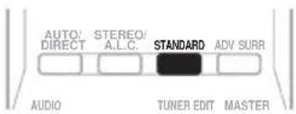
ADV SURR
Switches between the various surround modes (page 34).
The following button controls can be accessed after you have selected the corresponding MULTI CONTROL button (BD, TV, etc.).
Press RECEIVER first to access:
AUDIO PARAMETER
Use to access the Audio options (page 38).
SETUP
Press to access the System Setup menu (page 41).
RETURN
Confirm and exit the current menu screen.
Press BD or DVR first to access:
Displays the disc 'top' menu of a BD/DVD.
Displays the HOME MENU screen.
RETURN
Confirm and exit the current menu screen.
Displays the TOOLS menu screen of Blu-ray Disc player.
Press TUNER or SIRIUS first to access:
T.EDIT
Memorizes stations for recall (page 48 and 64). When TUNER is pressed, also used to change the name (page 49).
BAND
Switches between AM, FM ST (stereo) and FM MONO radio bands (page 48).
CATEGORY
Press to browse SIRIUS radio broadcasts.
Press iPod USB first to access:
iPod CTRL
Switches between the iPod controls and the receiver controls (page 60).
9 ↑↓ ↔ (TUNE ↑/↓, PRESET ←/→), ENTER
Use the arrow buttons when setting up your surround sound system (page 41). Also used to control BD/DVD menus/options.
Use the TUNE ↑/↓ buttons can be used to find radio frequencies (page 48) and the
PRESET ←/→ buttons can be used to select preset radio stations (page 49).
The main buttons (▶, ■, etc.) are used to control a component after you have selected it using the input source buttons.
The controls above these buttons can be accessed after you have selected the corresponding input source button (for example BD, DVR or TV). These buttons also function as described below.
Press RECEIVER first to access:
BASS -/+
Use to adjust Bass ^1
TRE -/+
Use to adjust Treble ^1
Press TV first to access:
ANT
Use to select the VHF/UHF antennas or Cable TV.
Use the number buttons to directly select a radio frequency (page 48) or the tracks on a CD, DVD, etc. There are other buttons that can be accessed after the RECEIVER button is pressed. (For example MIDNIGHT, etc.)
HDD\*, DVD\*, VCR\*
These buttons switch between the hard disk, DVD and VCR controls for HDD/DVD/VCR recorders.
Controls and displays
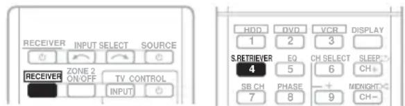
S.RETRIEVER
Press to restore CD quality sound to compressed audio sources (page 36).
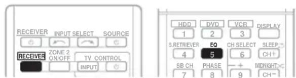
EQ
Press to switch on/off Acoustic Calibration EQ setting (page 36).
CH SELECT
Press repeatedly to select a channel, then use +/- to adjust the level (page 43).
CH SELECT +/-
Use to adjust the channel level.
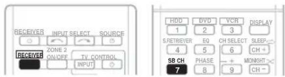
SB CH
Press to select ON, AUTO, OFF the surround back channel.
PHASE
Press to switch on/off Phase Control (page 11).
DIMMER
Dims or brightens the display. The brightness can be controlled in four steps.
SPEAKERS
Use to change the speaker system (page 25).
MIDNIGHT
Switches to Midnight or Loudness listening (page 38).
SLEEP
Press to change the amount of time before the receiver switches into standby (30 min – 60 min – 90 min – Off). You can check the remaining sleep time at any time by pressing SLEEP once.
Press SIRIUS first to access:
D.ACCESS
After pressing, you can access a radio station directly using the number buttons (page 63).
12 ⏻ SOURCE
Press to turn on/off other components connected to the receiver (see page 53 for more on this).
These buttons are dedicated to control the TV assigned to the TV button. Thus if you only have one TV to hook up to this system assign it to the TV button. (see page 52 for more on this).
[Non-Text]
Use to turn on/off the power of the TV.
Use to select the TV input signal.
CH +/-
Use to select channels.
VOL +/-
Use to adjust the volume on your TV.
14 MASTER VOLUME +/-
Use to set the listening volume.
15 MUTE
Mutes/unmutes the sound.
16 DISPLAY
Switches the display of this unit. The input name, listening mode or sound volume can be checked by selecting an input source.
17 SHIFT
Press to access the 'boxed' commands (above the buttons) on the remote. These buttons are marked with an asterisk (*) in this section. This button is also used for operating ZONE 2 (page 47).
Chapter 5:
Listening to your system

Important
- The listening modes and many features described in this section may not be available depending on the current source, setting and status of the receiver.
Auto playback
The simplest, most direct listening option is the Auto Surround feature. With this, the receiver automatically detects what kind of source you're playing and selects multichannel or stereo playback as necessary. ^1
- While listening to a source, press AUTO/DIRECT ^2 for auto playback of a source.
Press repeatedly until AUTO SURROUND shows briefly in the display (it will then show the decoding or playback format). Check the digital format indicators in the display to see how the source is being processed.
Listening in surround sound
Using this receiver, you can listen to any source in surround sound. However, the options available will depend on your speaker setup and the type of source you're listening to.
The following modes provide basic surround sound for stereo and multichannel sources.
- While listening to a source, press STANDARD.
If the source is Dolby Digital, DTS, or Dolby Surround encoded, the proper decoding format will automatically be selected and shows in the display.
When the surround back speaker is not connected
With two channel sources, you can select from:
• DOLBY PLII MOVIE – Up to 5.1 channel sound, especially suited to movie sources
- DOLBY PLII MUSIC ^3 – Up to 5.1 channel sound, especially suited to music sources
• DOLBY PLII GAME – Up to 5.1 channel sound, especially suited for video games
• DOLBY PRO LOGIC – 4.1 channel surround sound
When the surround back speaker is connected. ^4
If you connected surround back speakers, see also Using surround back channel processing on page 37.

Note
1 Stereo surround (matrix) formats are decoded accordingly using NEO:6 CINEMA or DOLBY PLIIx MOVIE (see Listening in surround sound above for more on these decoding formats).
2 For more options using this button, see Using Stream Direct on page 36.
3 When listening to 2-channel sources in DOLBY PLII MUSIC mode, there are three further parameters you can adjust: C.WIDTH, DIMEN., and PNRM.. See Setting the Audio options on page 38 to adjust them.
4 • If surround back channel processing (page 37) is switched off, or the surround back speakers are set to NO, DOLBY PLIIx becomes DOLBY PLII (5.1 channel sound).
- In modes that give 6.1 channel sound, the same signal is heard from both surround back speakers.
With two channel sources, you can select from:
- DOLBY PLIIx MOVIE – Up to 7.1 channel sound, especially suited to movie sources
- DOLBY PLIIx MUSIC – Up to 7.1 channel sound, especially suited to music sources ^1
- DOLBY PLIIx GAME – Up to 7.1 channel sound, especially suited to video games
- NEO:6 CINEMA – 6.1 channel sound, especially suited to movie sources
- NEO:6 MUSIC – 6.1 channel sound, especially suited to music sources ^2
- DOLBY PRO LOGIC – 4.1 channel surround sound (sound from the surround speakers is mono)
With multichannel sources, if you have connected surround back speaker(s) and have selected SB CH ON, you can select (according to format):
- DOLBY PLIIx MOVIE – See above (only available when you're using two surround back speakers)
• DOLBY PLIIx MUSIC – See above
- DOLBY DIGITAL EX – Creates surround back channel sound for 5.1 channel sources and provides pure decoding for 6.1 channel sources (like Dolby Digital Surround EX)
- DTS-ES – Allows you to hear 6.1 channel playback with DTS-ES encoded sources
- DTS NEO:6 – Allows you to hear 6.1 channel playback with DTS encoded sources
Using the Advanced surround effects
The Advanced surround feature creates a variety of surround effects. Try different modes with various soundtracks to see which you like.
- P r ADV SURR repeatedly to select a listening mode.
- ACTION – Designed for action movies with dynamic soundtracks.
- DRAMA – Designed for movies with lots of dialog.
- ENT.SHOW – Suitable for musical sources.
- ADVANCED GAME – Suitable for video games.
- SPORTS – Suitable for sports programs.
- CLASSICAL – Gives a large concert hall-type sound.
- ROCK/POP – Creates a live concert sound for rock and/or pop music.
- UNPLUGGED – Suitable for acoustic music sources.
- EXT.STEREO – Gives multichannel sound to a stereo source, using all of your speakers.

Note
1 When listening to 2-channel sources in DOLBY PLIIx MUSIC mode, there are three further parameters you can adjust: C.WIDTH, DIMEN., and PNRM.. See Setting the Audio options on page 38 to adjust them.
2 When listening to 2-channel sources in NEO:6 CINEMA or NEO:6 MUSIC mode, you can also adjust the C.IMG effect (see Setting the Audio options on page 38).
Listening in stereo
When you select STEREO you will hear the source through just the front left and right speakers (and possibly your subwoofer depending on your speaker settings). Dolby Digital and DTS multichannel sources are downmixed to stereo.
In the Auto level control stereo mode (A.L.C.), this unit equalizes playback sound levels if each sound level varies with the music source recorded in a portable audio player.
- While listening to a source, press STEREO/A.L.C. for stereo playback.
Press repeatedly to switch between:
- STEREO – The audio is heard with your surround settings and you can still use the Midnight, Loudness, Phase Control, Sound Retriever and Tone functions.
• A.L.C. – Listening in Auto level control stereo mode.
- F.S.S.ADVANCE – See Using Front Stage Surround Advance below for more on this.
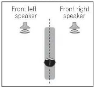
Using Front Stage Surround Advance
The Front Stage Surround Advance function allows you to create natural surround sound effects using just the front speakers and the subwoofer.
- While listening to a source, press STEREO/A.L.C. to select Front Stage Surround Advance modes.
- STEREO – See Listening in stereo above for more on this.
• A.L.C. – See Listening in stereo above for more on this.
- F.S.S.ADVANCE – Use to provide a rich surround sound effect directed to the center of where the front left and right speakers sound projection area converges.
F.S.S.ADVANCE position
Using Stream Direct
Use the Stream Direct modes when you want to hear the truest possible reproduction of a source. All unnecessary signal processing is bypassed.
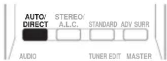
- While listening to a source, press AUTO/DIRECT to select Stream Direct mode.
- AUTO SURROUND – See Auto playback on page 33.
- DIRECT – Sources are heard according to the settings made in the Surround Setup (speaker setting, channel level, speaker distance), as well as with dual mono settings. ^1 You will hear sources according to the number of channels in the signal.
- PURE DIRECT – Analog and PCM sources are heard without any digital processing ^2 .
Using the Sound Retriever
When audio data is removed during the compression process, sound quality often suffers from an uneven sound image. The Sound Retriever feature employs new DSP technology that helps bring CD quality sound back to compressed 2-channel audio by restoring sound pressure and smoothing jagged artifacts left over after compression. ^3
- P r RECEIVER, then press S.RETRIEVER to switch the sound retriever on or off.
Listening with Acoustic Calibration EQ
- Default setting: ON
You can listen to sources using the Acoustic Calibration Equalization set in Automatically setting up for surround sound (MCACC) on page 9. Refer to these pages for more on Acoustic Calibration Equalization.
- While listening to a source, press RECEIVER, then press EQ to switch the Acoustic Calibration EQ on or off.
The MCACC indicator on the front panel lights when Acoustic Calibration EQ is active. ^4

Note
1 In the DIRECT mode, Phase Control, Acoustic Calibration EQ, Sound Delay, Auto Delay, LFE Attenuate and Center image functions are available.
2 There are cases where a brief noise is heard before playback of sources other than PCM. Please select AUTO SURROUND or DIRECT if this is a problem.
3 The Sound Retriever is only applicable to 2-channel sources.
4 You can't use Acoustic Calibration EQ with MULTI IN or Stream Direct mode and it has no effect with headphones.
Using surround back channel processing
You can set the surround back channel when the surround back speaker is connected and NO is not selected for the speaker setting (page 42).
You can have the receiver automatically use 6.1 or 7.1 decoding for 6.1 encoded sources (for example, Dolby Digital EX or DTS-ES), or you can choose to always use 6.1 or 7.1 decoding (for example, with 5.1 encoded material). With 5.1 encoded sources, a surround back channel will be generated, but the material may sound better in the 5.1 format for which it was originally encoded (in which case, you can simply switch surround back channel processing off).
- Press RECEIVER, then press SB CH repeatedly to cycle the surround back channel options.
Each press cycles through the options as follows:
- SB CH ON – 6.1 or 7.1 decoding is always used (for example, a surround back channel will be generated for 5.1 encoded material)
- SB CH AUTO – Automatically switches to 6.1 or 7.1 decoding for 6.1 encoded sources (for example, Dolby Digital EX or DTS-ES)
- SB CH OFF – No sound is output from the surround back speakers
Setting the Up Mix function
In a 7.1-channel surround system with surround speakers placed directly at the sides of the listening position, the surround sound of 5.1-channel sources is heard from the side. The Up Mix function mixes the sound of the surround speakers with the surround back speakers so that the surround sound is heard from diagonally to the rear as it should be. ^1
- Using the Up Mix function is effective when the speakers in the 7.1-channel surround system are set up as recommended in the example on page 24.
- Depending on the positions of the speakers and the sound source, in some cases it may not be possible to achieve good results. In this case, set the setting to OFF.
1 Switch the receiver into standby.
2 While holding down the PRESET+ on the front panel, and hold the ⏻ STANDBY/ON for about two seconds.
UP MIX: OFF appears and the Up Mix function turns off. If you want to turn this function on, perform steps 1 and 2 again.
- When set to ON, the UP MIX indicator on the front panel lights.

Note
1 • Set to ON regardless of this setting when playing DTS-HD signals.
- May automatically be set to OFF even when set to ON, depending on the input signal and listening mode.
Setting the Audio options
There are a number of additional sound settings you can make using the AUDIO PARAMETER menu. The defaults, if not stated, are listed in bold.

Important
- The AUDIO PARAMETER menu is not available with MULTI IN input (see Selecting the multichannel analog inputs on page 40).
- Note that if a setting doesn't appear in the AUDIO PARAMETER menu, it is unavailable due to the current source, settings and status of the receiver.
2 U ↑/↓ to select the setting you want to adjust.
Depending on the current status/mode of the receiver, certain options may not be able to be selected. Check the table below for notes on this.
3 U ←/→ to set it as necessary.
See the table below for the options available for each setting.
4 Press RETURN to confirm and exit the menu.
Setting What it does Option(s)
| EQ(Acoustic Calibration EQ) | Switches on/off the effect of Acoustic Calibration EQ. ON | |
| OFF |
| S.DELAY(Sound Delay) | Some monitors have a slight delay when showing video, so the soundtrack will be slightly out of sync with the picture. By adding a bit of delay, you can adjust the sound to match the presentation of the video. | 0.0 to 9.0 (frames)1 second = 30 frames(NTSC)Default: 0.0 |
| MIDNIGHTa | Allows you to hear effective surround sound of movies at low volumes. | M/L OFF |
| MIDNIGHT |
| LOUDNESSa | Used to get good bass and treble from music sources at low volumes. | LOUDNESS |
| S.RTVb(Sound Retriever) | When audio data is removed during the WMA/MP3ccompression process, sound quality often suffers from an uneven sound image. The Sound Retriever feature employs new DSP technology that helps bring CD quality sound back to compressed 2-channel audio by restoring sound pressure and smoothing jagged artifacts left over after compression. | OFF |
| ON |
| DUAL MONOd | Specifies how dual mono encoded Dolby Digital soundtracks should be played. | CH1 –Channel 1 is heard only |
| CH2 –Channel 2 is heard only |
| CH1 CH2 –Both channels heard from front speakers |
| Setting What it does Option(s) |
| DRC(Dynamic Range Control) | Adjusts the level of dynamic range for movie soundtracks optimized for Dolby Digital, DTS, Dolby Digital Plus, Dolby TrueHD, DTS-HD and DTS-HD Master Audio (you may need to use this feature when listening to surround sound at low volumes). | AUTO^e |
| MAX |
| MID |
| OFF |
| LFE ATT(LFE Attenuate) | Some Dolby Digital and DTS audio sources include ultra-low bass tones. Set the LFE attenuator as necessary to prevent the ultra-low bass tones from distorting the sound from the speakers.The LFE is not limited when set to 0 dB, which is the recommended value. When set to -10 dB, the LFE is limited by the respective degree. When OFF is selected, no sound is output from the LFE channel. | LFEATT 0 (0 dB) |
| LFEATT 10 (-10 dB)/LFEATT ** (OFF) |
| HDMI(HDMI Audio) | Specifies the routing of the HDMI audio signal out of this receiver (amp) or through to a TV or flat panel TV. When THRU is selected, no sound is output from this receiver. | AMP |
| THRU |
| A.DLY(Auto Delay) | This feature automatically corrects the audio-to-video delay between components connected with an HDMI cable. The audio delay time is set depending on the operational status of the display connected with an HDMI cable. The video delay time is automatically adjusted according to the audio delay time. ^f | OFF |
| ON |
| C.WIDTH9(Center Width)(Applicable only when using a center speaker) | Spreads the center channel between the front right and left speakers, making it sound wider (higher settings) or narrower (lower settings). | 0 to 7Default: 3 |
| DIMEN.9(Dimension) | Adjusts the surround sound balance from front to back, making the sound more distant (minus settings), or more forward (positive settings). | -3 to +3Default: 0 |
| PNRM.9(Panorama) | Extends the front stereo image to include surround speakers for a 'wraparound' effect. | OFF |
| ON |
| C.IMG ^h (Center image)(Applicable only when using a center speaker) | Adjust the center image to create a wider stereo effect with vocals. Adjust the effect from 0 (all center channel sent to front right and left speakers) to 10 (center channel sent to the center speaker only). | 0 to 10Default: 3(NEO:6 MUSIC),10 (NEO:6 CINEMA) |
a. You can change the MIDNIGHT/LOUDNESS options at any time by using MIDNIGHT button.
b. You can change the Sound Retriever feature at any time by using S.RETRIEVER button.
c. WMA and MP3 playback available only via iPod/USB input.
d. This setting works only with dual mono encoded Dolby Digital and DTS soundtracks.
e. The initial set AUTO is only available for Dolby TrueHD signals. Select MAX or MID for signals other than Dolby TrueHD.
f. This feature is only available when the connected display supports the automatic audio/video synchronizing capability ('lip-sync') for HDMI. If you find the automatically set delay time unsuitable, set A.DLY to OFF and adjust the delay time manually. For more details about the lip-sync feature of your display, contact the manufacturer directly.
g. Only available with 2-channel sources in DOLBY PLII MUSIC mode.
h. Only when listening to 2-channel sources in NEO:6 CINEMA and NEO:6 MUSIC mode.
Playing other sources
1 Turn on the power of the playback component.
2 Turn on the power of the receiver.
3 Select the source you want to playback. Use the MULTI CONTROL buttons (INPUT SELECTOR).
4 Start playback of the component you selected in step 1.
On this receiver, it is possible to switch the input signals for the different inputs as described below. ^1
1 Press RECEIVER on the remote control.
2 Press SIGNAL SEL to select the input signal corresponding to the source component.
When DIGITAL (C1/O1/O2) or HDMI (H) is selected and the selected audio input is not provided, A (analog) is automatically selected.
Each press cycles through the following:
- A – Selects the analog inputs.
- DIGITAL – Selects the digital input. The coaxial 1 input is selected for C1, and the optical 1 or 2 audio input is selected for O1 or O2.
- HDMI – Selects an HDMI signal. H can be selected for BD/DVD, TV/SAT or DVR/VCR input. For other inputs, HDMI cannot be selected. ^2
When set to DIGITAL or HDMI, lights when a Dolby Digital signal is input, and DTS lights when a DTS signal is input.
When the HDMI is selected, the A and DIGITAL indicators are off (see page 29).
If you have connected a decoder or a BD/DVD player with multichannel analog outputs to this receiver (page 15), you must select the analog multichannel inputs for surround sound. ^3
- Press MULTI IN on the remote control. To cancel playback from the multichannel inputs, switches to the other input signal.
Using the headphone
1 Insert the headphone into the PHONE jack.
2 Press RECEIVER then press the SPEAKERS button to select SP OFF.
The sound is heard from the headphone and no sound is heard from the speakers connected to this receiver. The listening mode when the sound is heard from the headphone can be selected only from STEREO or A.L.C..
Note
1 • This receiver can only play back Dolby Digital, PCM (32 kHz to 96 kHz) and DTS (including DTS 96 kHz / 24 bit) digital signal formats. The compatible signals via the HDMI terminals are: Dolby Digital, DTS, SACD (DSD 2 ch), PCM (32 kHz to 192 kHz sampling frequencies), Dolby TrueHD, Dolby Digital Plus, DTS-EXPRESS, DTS-HD Master Audio and DVD Audio (including 192 kHz). With other digital signal formats, set to A (analog) (the MULTI IN or TUNER).
- You may get digital noise when a LD or CD player compatible with DTS is playing an analog signal. To prevent noise, make the proper digital connections (page 14) and set the signal input to C1/O1/O2 (DIGITAL).
- Some DVD players don't output DTS signals. For more details, refer to the instruction manual supplied with your DVD player.
2 When the HDMI option in Setting the Audio options on page 38 is set to THRU, the sound will be heard through your TV, not from this receiver.
3 • During playback from the multichannel inputs, you can't use any of the sound features/modes and only the volume and channel levels can be set.
- Change the output settings of the systems with multichannel analog outputs according to the number of the speakers connected to the receiver.
Chapter 6:
The following section shows you how to make detailed settings to specify how you're using the receiver, and also explains how to fine-tune individual speaker system settings to your liking.
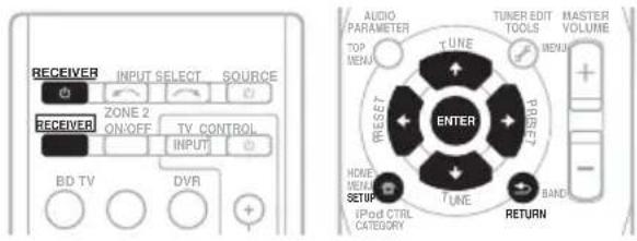
1 Switch on the receiver and your TV. Use the ⏻ RECEIVER button to switch on. ^1
An on-screen display (OSD) appears on your TV. Use ↑/↓/←/→ and ENTER on the remote control to navigate through the screens and select menu items. Press RETURN to confirm and exit the current menu.
3 Select the setting you want to adjust.
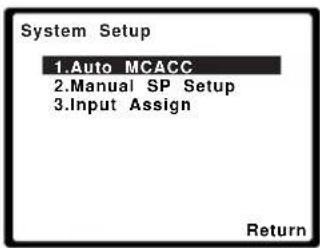
- Auto MCACC – This is a quick and effective automatic surround setup (see Automatically setting up for surround sound (MCACC) on page 9).
- Manual SP Setup – Specify the size, number, distance and overall balance of the speakers you've connected (see Manual speaker setup on page 41).
- Input Assign – Specify what you've connected to the component video inputs (see The Input Assign menu on page 44).
Manual speaker setup
This receiver allows you to make detailed settings to optimize the surround sound performance. You only need to make these settings once (unless you change the placement of your current speaker system or add new speakers).
These settings are designed to fine-tune your system, but if you're satisfied with the settings made in Automatically setting up for surround sound (MCACC) on page 9, it isn't necessary to make all of these settings.

Caution
- The test tones used in the System Setup are output at high volume.
Note
1 If headphones are connected to the receiver, disconnect them.
2 • You can't use the System Setup menu when the iPod/USB input is selected.
- Press SETUP at any time to exit the System Setup menu.
- The OSD will not appear if you have connected using the HDMI output to your TV. Use component or composite connections for system setup.
1 Select 'Manual SP Setup' then press ENTER.
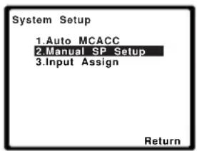

2 Select the setting you want to adjust.
If you are doing this for the first time, you may want to adjust these settings in order:
- Speaker Setting – Specify the size and number of speakers you've connected (see below).
- Crossover Network – Specify which frequencies will be sent to the subwoofer (page 43).
- Channel Level – Adjust the overall balance of your speaker system (page 43).
- Speaker Distance – Specify the distance of your speakers from the listening position (page 44).
3 Make the adjustments necessary for each setting, pressing RETURN to confirm after each screen.
Speaker Setting
Use this setting to specify your speaker configuration (size, number of speakers). It is a good idea to make sure that the settings made in Automatically setting up for surround sound (MCACC) on page 9 are correct.
1 Select 'Speaker Setting' from the Manual SP Setup menu.
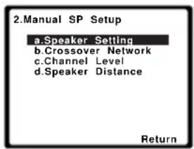
![2a.Speaker Setting Front SMALL Center [ SMALL ] Surr [ SMALL ] Surr. Back [ NO ] Subwoofer: YES Return](/content/2026/02/379021/images/e22ee7154b12537a6685fe0eeddb9746a446228cae1e2bd97eb7f322640d5c53.jpg)
2 Choose the set of speakers that you want to set then select a speaker size.
Use / to select the size (and number) of each of the following speakers:
- Front – Select LARGE if your front speakers reproduce bass frequencies effectively, or if you didn't connect a subwoofer. Select SMALL to send the bass frequencies to the subwoofer. ^1
- Center – Select LARGE if your center speaker reproduces bass frequencies effectively, or select SMALL to send bass frequencies to the other speakers or subwoofer. If you didn't connect a center speaker, choose NO (the center channel is sent to the other speakers).
- Surr – Select LARGE if your surround speakers reproduce bass frequencies effectively. Select SMALL to send bass frequencies to the other speakers or subwoofer. If you didn't connect surround speakers choose NO (the sound of the surround channels is sent to the other speakers).

Note
1 If you select SMALL for the front speakers, the subwoofer will automatically be fixed to YES. Also, the center, surround and surround back speakers can't be set to LARGE if the front speakers are set to SMALL. In this case, all bass frequencies are sent to the subwoofer.
- Surr. Back – Select the number of surround back speakers you have (one, two or none). ^1 Select LARGE if your surround back speakers reproduce bass frequencies effectively. Select SMALL to send bass frequencies to the other speakers or subwoofer. If you didn't connect surround back speakers choose NO.
- Subwoofer – LFE signals and bass frequencies of channels set to SMALL are output from the subwoofer when YES is selected (see notes below). Choose the PLUS setting if you want the subwoofer to output bass sound continuously or you want deeper bass (the bass frequencies that would normally come out the front and center speakers are also routed to the subwoofer). If you did not connect a subwoofer choose NO (the bass frequencies are output from other speakers).
3 When you're finished, press RETURN.
You return to the Manual SP Setup menu.

Tip
- If you have a subwoofer and like lots of bass, it may seem logical to select LARGE for your front speakers and PLUS for the subwoofer. This may not, however, yield the best bass results. Depending on the speaker placement of your room you may actually experience a decrease in the amount of bass due to low frequency cancellations. In this case, try changing the position or direction of speakers. If you can't get good results, listen to the bass response with it set to PLUS and YES or the front speakers set to LARGE and SMALL alternatively and let your ears judge which sounds best. If you're having problems, the easiest option is to route all the bass sounds to the subwoofer by selecting SMALL for the front speakers.
Crossover Network
- Default setting: 100Hz
This setting decides the cutoff between bass sounds playing back from the speakers selected as LARGE, or the subwoofer, and bass sounds playing back from those selected as SMALL. It also decides where the cutoff will be for bass sounds in the LFE channel. ^2
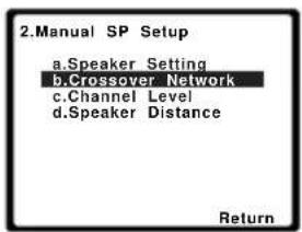
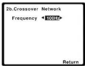
2 Choose the frequency cutoff point.
Frequencies below the cutoff point will be sent to the subwoofer (or LARGE speakers).
3 When you're finished, press RETURN.
You return to the Manual SP Setup menu.
Channel Level
Using the channel level settings, you can adjust the overall balance of your speaker system, an important factor when setting up a home theater system.
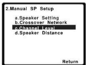
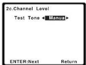
Note
1 • If the surround speakers are set to NO, the surround back speakers will automatically be set to NO.
- If you select one surround back speaker only, make sure that additional amplifier is hooked up to the PRE OUT SURROUND BACK L (Single) terminal.
2 Select a setup option.
- Manual – Move the test tone manually from speaker to speaker and adjust individual channel levels.
- Auto – Adjust channel levels as the test tone moves from speaker to speaker automatically.
3 Confirm your selected setup option.
The test tones will start after you press ENTER. After the volume increases to the reference level, test tones will be output.
![2c.Channel Level Test Tone [Manual] Please Wait...20 Caution Loud test tones will be output. Return](/content/2026/02/379021/images/1e1af3e915d61fddac53916a623f9ae83903fdda0d2a5fea5367889e6577f57d.jpg)
4 Adjust the level of each channel using

If you selected Manual, use ↑/↓ to switch speakers. The Auto setup will output test tones in the order shown on-screen:
![2c.Channel Level Front L 0dB Center [0dB] Front R [0dB] Surround R [0dB] Surr. Back R [----] Surr. Back L [----] Surround L [0dB] Subwoofer [0dB] Return](/content/2026/02/379021/images/56d4597b02305ff718110f5eba8c1b6fa0a7adec5eb036a2eae6b40ff4e65b6f.jpg)
Adjust the level of each speaker as the test tone is emitted. ^1
5 When you're finished, press RETURN.
You return to the Manual SP Setup menu.

Tip
- You can change the channel levels at any time by press RECEIVER, then press CH SELECT and +/- on the remote control. You can also press CH SELECT and use / to select the channel, and then use / to adjust the channel levels.
Speaker Distance
For good sound depth and separation from your system, you need to specify the distance of your speakers from the listening position. The receiver can then add the proper delay needed for effective surround sound.
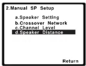
![2d.Speaker Distance Front L 10.0 ft Center [ 10.0 ft ] Front R [ 10.0 tt ] Surround R [ 10.0 ft ] Surr. Back R [ ---- ] Surr. Back L [ ---- ] Surround L [ 10.0 ft ] Subwoofer [ 10.0 ft ] Return](/content/2026/02/379021/images/13f24f8c8707ff182a4395ea4719eb752ea1ac5ed8b4bcbab5c30f562e741eb5.jpg)
2 Adjust the distance of each speaker using / .
You can adjust the distance of each speaker in 0.1 feet increments.
3 When you're finished, press RETURN.
You return to the Manual SP Setup menu.
You only need to make settings in the Input Assign menu if you have connected equipment using component video cables.
- Default settings:
Component 1 – BD
Component 2 – TV
If your component is connected via a component video cable to an input terminal other than the default, you must tell the receiver which input terminal your component is connected to, or else you may see the composite video input instead of the component video signal. For more on this, see Using the component video jacks on page 19.

Note
1 • If you are using a Sound Pressure Level (SPL) meter, take the readings from your main listening position and adjust the level of each speaker to 75 dB SPL (C-weighting/slow reading).
- The subwoofer test tone is output at low volumes. You may need to adjust the level after testing with an actual soundtrack.
An on-screen display (OSD) appears on your TV. Use ↑/↓/←/→ and ENTER on the remote control to navigate through the screens and select menu items. Press RETURN to confirm and exit the current menu.
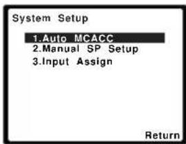
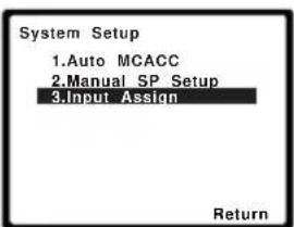
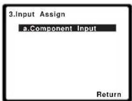
![3a.Component Input Component-1 BD Component-2 [ TV ] Return](/content/2026/02/379021/images/bb55d8c1f6478f26918773b21781b85c10d74f91d0915c997c7d15a1611b72aa.jpg)
The numbers correspond with the numbers beside the inputs on the rear of the receiver.
Select between BD, TV, DVR, MULTI (MULTI CH IN) or OFF.
- Use / and ENTER to do this.
- If you assign a component input to a certain function, any component inputs previously assigned to that function will automatically be switched off.
- Make sure you have connected the audio from the component to the corresponding inputs on the rear of the receiver.
- If you connect any source component to the receiver using a component video input, you should also have your TV connected to this receiver's COMPONENT VIDEO OUT output (down converting component video is not possible after assigning an input).
6 When you're finished, press RETURN.
You return to the Input Assign menu.
Chapter 7:
Using the MULTI-ZONE feature
MULTI-ZONE listening
This receiver can power up to two independent systems in separate rooms after you have made the proper MULTI-ZONE connections. An example MULTI-ZONE setup is shown below.
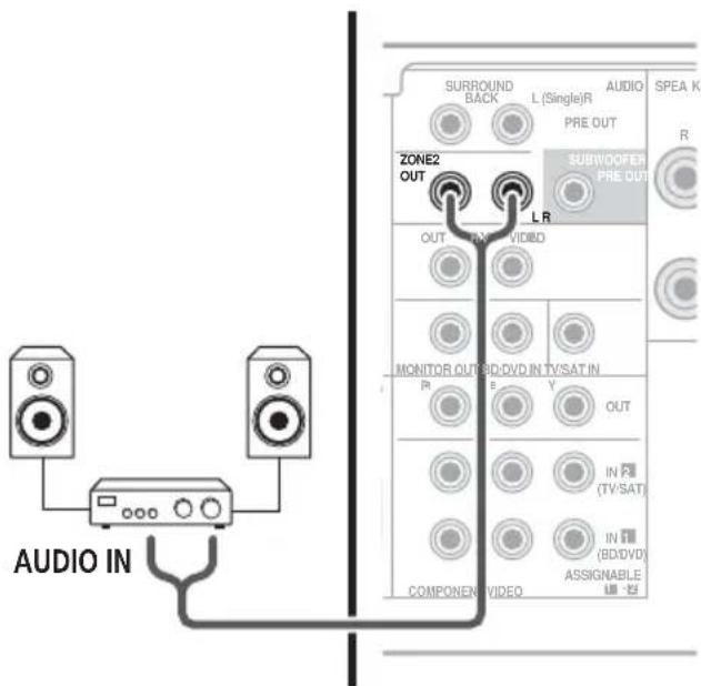
Different sources can be playing in two zones at the same time or, depending on your needs, the same source can also be used. The main and sub zones have independent power (the main zone power can be off while the sub zone is on) and the sub zone can be controlled by the remote or front panel controls.
Making MULTI-ZONE connections
It is possible to make these connections if you have a separate speakers for your sub zone (ZONE 2). ^1 You will also need a separate amplifier for your sub zone.
MULTI-ZONE listening options
The following table shows what you can listen to in the sub zone:
ZONE 2 The built-in tuner and other analog audio sources. ^a
a. You cannot select the MULTI IN inputs and iPod/USB inputs in ZONE 2.
Basic MULTI-ZONE setup (ZONE 2)
- Connect a separate amplifier to the ZONE 2 AUDIO OUT jacks on the rear of this receiver.
You should have a pair of speakers attached to the sub zone amplifier as shown in the following illustration.
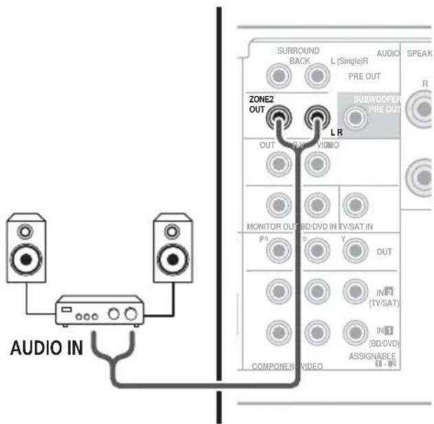

Note
1 You can't use sound controls (such as the bass/treble controls or Midnight listening) or any surround modes with a separate amplifier in the sub zone. You can, however, use the features available with your sub zone amplifier.
Using the MULTI-ZONE controls
The following steps use the front panel controls to select sources. See MULTI-ZONE remote controls below.
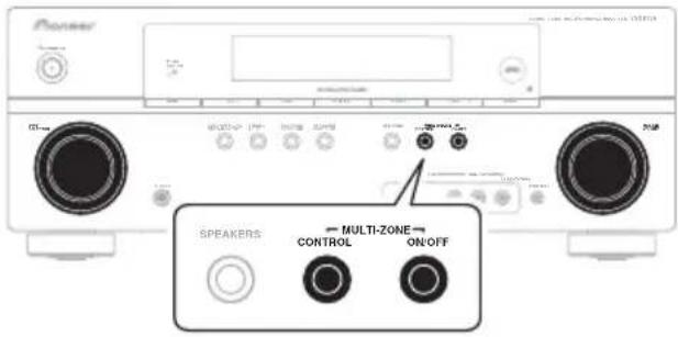
Each press selects a MULTI-ZONE option:
- ZONE 2 ON – Switches the MULTI-ZONE feature on
- ZONE 2 OFF – Switches the MULTI-ZONE feature off
The ZONE indicator lights when the MULTI-ZONE control has been switched ON.
2 Press CONTROL.
- When the receiver is on, ^1 make sure that any operations for the sub zone are done while ZONE 2 shows in the display. If this is not showing, the front panel controls affect the main zone only.
3 U s dNPUT SELECTOR dial to select the source for the zone you have selected.
For example, Z2: CDR sends the source connected to the CDR inputs to the sub room (ZONE 2).
- If you select TUNER, you can use the tuner controls to select a preset station (see Saving station presets on page 48 if you're unsure how to do this). ^2 If you select SIRIUS, you can only switch between PRESET modes.
4 When you're finished, press CONTROL again to return to the main zone controls.
You can also press the MULTI-ZONE ON/OFF button on the front panel to switch off all output to the sub zone. ^3
MULTI-ZONE remote controls
Press the RECEIVER button on the remote control, then with the SHIFT button pressed, press the buttons below to operate the corresponding zone.
The following table shows the possible MULTI-ZONE remote controls:
| Button | What it does |
| ZONE 2ON/OFFa | Switches on/off power in the sub zone. |
| INPUT SELECT | Use to select the input source in the sub zone. |
| MULTI CONTROL buttons | Use to select the input source directly in the sub zone. |
a. Without pressing the SHIFT button, you can switch power on/off in the sub zone.

Note
1 If the receiver is in standby, the display is dimmed, and ZONE2 ON continues to show in the display.
2 The tuner cannot be tuned to more than one station at a time. Therefore, changing the station in one zone also changes the station in the other zone. Please be careful not to change stations when recording a radio broadcast.
3 • You won't be able to switch the main zone off completely unless you've switched off the MULTI-ZONE control first.
- If you don't plan to use the MULTI-ZONE feature for a while, turn off the power in both the sub and main rooms so that this receiver is in standby.
• Volume level cannot be adjusted with this receiver. Use the separate amplifier connected to the ZONE2 OUT to adjust the volume.
Chapter 8:
Using the tuner
Listening to the radio
The following steps show you how to tune in to FM and AM radio broadcasts using the automatic (search) and manual (step) tuning functions. Once you are tuned to a station you can memorize the frequency for recall later—see Saving station presets below for more on how to do this.
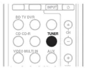
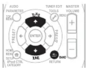
flowchart
graph TD
    A["Top MENU"] --> B["TUNE"]
    C["PRESET"] --> D["ENTER"]
    E["HOME MENU"] --> F["BAND"]
    G["SETUP"] --> H["IPoD CTRL CATEGORY"]
    I["INPUT"] --> J["RETURN"]
    K["TUNER EDIT TOOLS"] --> L["MENU"]
    M["MASTER VOLUME"] --> N["+ -"]
1 Press TUNER to select the tuner.
2 Use BAND to change to BAND (FM or AM), if necessary.
Each press switches the band between FM (stereo or mono) and AM.
3 Tune to a station.
There are three ways to do this:
Automatic tuning
To search for stations in the currently selected band, press and hold TUNE ↑/↓ for about a second. The receiver will start searching for the next station, stopping when it has found one. Repeat to search for other stations.
Manual tuning
To change the frequency one step at a time, press TUNE ↑/↓.
High speed tuning
Press and hold TUNE ↑/↓ for high speed tuning. Release the button at the frequency you want.
Improving FM stereo sound
If the TUNE or ST indicators don't light when tuning to an FM station because the signal is weak, press the BAND button to select FM MONO and set the receiver to the mono reception mode. This should improve the sound quality and allow you to enjoy the broadcast.
Saving station presets
If you often listen to a particular radio station, it's convenient to have the receiver store the frequency for easy recall whenever you want to listen to that station. This saves the effort of manually tuning in each time. This unit can memorize up to 30 stations. When saving an FM frequency. ^1
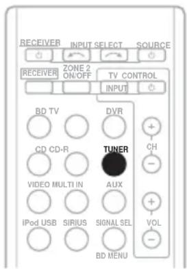
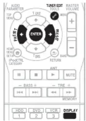
1 Tune to a station you want to memorize.
See Listening to the radio above for more on this.
2 Press TUNER EDIT.
The display shows PRESET, then a blinking MEM and station preset.

Note
1 If the receiver is left disconnected from the AC power outlet for over a month, the station memories will be lost and will have to be reprogrammed.
Using the tuner
3 Press PRESET ←/→ to select the station preset you want.
You can also use the number buttons.
4 Press ENTER.
After pressing ENTER, the preset number stop blinking and the receiver stores the station.
Listening to station presets
You will need to have some presets stored to do this. See Saving station presets on page 48 if you haven't done this already.
1 Press PRESET ←/→ to select the station preset you want.
- You can also use the number buttons on the remote control to recall the station preset.
Naming preset stations
For easier identification, you can name all of your preset stations.
1 Choose the station preset you want to name.
See Listening to station presets above for how to do this.
2 Press TUNER EDIT twice.
The cursor at the first character position is blinking on the display.
Choose a name up to eight characters long.
- Use the PRESET ←/→ buttons to select character position.
- Use the TUNE ↑/↓ buttons to select characters.
- The name is stored when ENTER is pressed.

Tip
- To erase a station name, follow steps 1 and 2, and press ENTER while the display is blank. Press TUNER EDIT while the display is blank, to keep the previous name.
- Once you have named a station preset, Press DISPLAY to show the name. When you want to return to the frequency display, press DISPLAY several times to show the frequency.
Chapter 9:
Making recordings
Making an audio or a video recording
You can make an audio or a video recording from the built-in tuner, or from an audio or video source connected to the receiver (such as a CD player or TV).
Keep in mind you can't make a digital recording from an analog source or vice-versa, so make sure the components you are recording to/from are hooked up in the same way (see Connecting up on page 12 for more on connections).
If you want to record a video source, you also need to use the same type of connection for the source as for the recorder. For example, you can't record a component hooked up to composite video jacks with a recorder hooked up to the component video outputs (see page 18 for more on video connections).
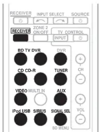
1 Select the source you want to record.
Use the MULTI CONTROL buttons (or INPUT SELECT).
2 Select the input signal (if necessary). Press the RECEIVER button then press SIGNAL SEL to select the input signal corresponding to the source component (see page 40 for more on this).
3 Prepare the source you want to record. Tune to the radio station, load the CD, video, DVD etc.
4 Prepare the recorder.
Insert a blank tape, MD, video etc. into the recording device and set the recording levels. Refer to the instructions that came with the recorder if you are unsure how to do this. Most video recorders set the audio recording level automatically—check the component's instruction manual if you're unsure.
5 Start recording, then start playback of the source component. ^1

Note
• The receiver's volume, balance, tone (bass, treble, loudness), and surround effects have no effect on the recorded signal.
- Some digital sources are copy-protected, and can only be recorded in analog.
- Some video sources are copy-protected. These cannot be recorded.
Chapter 10:
Controlling the rest of your system
Setting the remote to control other components
Most components can be assigned to one of the MULTI CONTROL buttons using the component's manufacturer preset code stored in the remote.
However, please note that there are cases where only certain functions may be controllable after assigning the proper preset code, or the codes for the manufacturer in the remote control will not work for the model that you are using. ^1

Note
- You can cancel or exit any of the steps by pressing RECEIVER.
• After one minute of inactivity, the remote automatically exits the operation.
Selecting preset codes directly
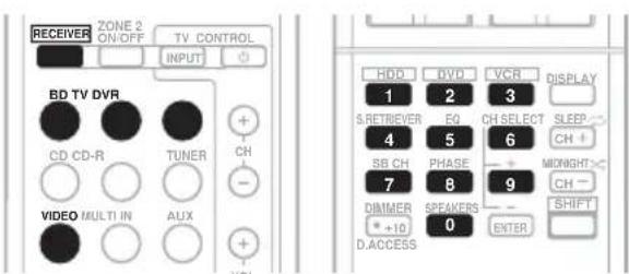
1 While pressing the RECEIVER button, press and hold the '1' button for three seconds.
2 Press the MULTI CONTROL button for the component you want to control.
The component can be assigned to the BD, TV, DVR or VIDEO button.
3 Use the number buttons to enter the preset code.
You can find the preset codes on page 55.
If the correct code has been input the power of the component being input will turn on or off.
The power of the component being input will only turn on or off if that component is able to be turned on directly by remote control.
4 Repeat steps 2 through 3 to try a different code, or to enter a code for another component you want to control.
5 When you're done, press RECEIVER.
Clearing all the remote control settings
You can clear all presets and restore the factory default settings.
- While pressing the RECEIVER button, press and hold the '0' button for three seconds.

Note
Controls for TVs
This remote control can control components after entering the proper codes or teaching the receiver the commands (see Controlling the rest of your system on page 51 for more on this). Use the MULTI CONTROL buttons to select the component
- The TV CONTROL buttons on the remote control are dedicated to control the TV assigned to the TV button.
Button(s) Function Components
| TV CONTROL ⏻ | Switches the DTV on or off. | DTV |
| Switches the TV or CATV between standby and on. | Cable TV/Satellite TV/TV |
| TV CONTROL INPUT | Switches the TV input. (Not possible with all models.) | TV |
| TV CONTROL CH +/- | Selects channels. | Cable TV/Satellite TV/TV/DTV |
| TV CONTROL VOL +/- | Adjust the TV volume. | Cable TV/Satellite TV/TV/DTV |
| SOURCE | Press to switch the component assigned to the TV button on or off. | Cable TV/Satellite TV/TV/DTV |
| ANT Use to select the VHF/UHF antennas or Cable TV. | Cable TV/TV |
| HOME MENU | Use as the GUIDE button for navigating. | Cable TV/Satellite TV/TV/DTV |
| RETURN Use to select closed captioning with DTV. | DTV |
| Number buttons | Use to select a specific TV channel. | Cable TV/Satellite TV/TV/DTV |
| +10 button Use to add a decimal points when selecting TV channels. | DTV |
| ENTER Use to enter a channel. | Cable TV/Satellite TV/TV/DTV |
| MENU Press to display the DTV menu. | DTV |
| Select the menu screen. | Cable TV/Satellite TV/TV |
| ←→↓↑ & ENTER | Press to select or adjust and navigate items on the menu screen. | Cable TV/Satellite TV/TV/DTV |
| CH +/- | Selects channels. | Cable TV/Satellite TV/TV/DTV |
Controls for other components
This remote control can control these components after entering the proper codes or teaching the receiver the commands (see Controlling the rest of your system on page 51 for more on this). Use the MULTI CONTROL buttons to select the component.
Button(s) Function Components
| SOURCE | Press to switch the component between standby and on. | BD/CD/MD/CD-R/VCR/DVD/LD/ DVR player/Cassette deck |
| ◄◄ Press to return to the start of the current track.Repeated presses skips to the start of previous tracks. | BD/CD/MD/CD-R/VCR/DVD/DVR/LD player |
| ►►I Press to advance to the start of the next track.Repeated presses skips to the start of following tracks. | BD/CD/MD/CD-R/VCR/DVD/DVR/LD player |
| ■ Pause playback or recording. BD/CD/MD/CD-R/VCR/ | DVD/LD/DVR player/Cassette deck |
| ► Start playback. BD/CD/MD/CD-R/VCR/ | DVD/LD/DVR player/Cassette deck |
| ►► Hold down for fast forward playback. BD/CD/MD/CD-R/VCR/ | DVD/LD/ DVR player/Cassette deck |
| ◄◄ Hold down for fast reverse playback. BD/CD/MD/CD-R/VCR/ | DVD/LD/DVR player/Cassette deck |
| ■ Stops playback (on some models, pressing this when the disc is already stopped will cause the disc tray to open). | BD/CD/MD/CD-R/VCR/DVD/LD/DVR player/Cassette deck |
| Number buttons | Directly access tracks on a program source. | CD/MD/CD-R/VCR/LD player |
| Use to enter a title/chapter/track number. | BD/DVD/DVR player |
| +10 button | Selects tracks higher than 10. (For example, press +10 then 3 to select track 13.) | BD/DVD/CD/MD/CD-R/VCR/LD player |
| ENTER | Chooses the disc. | Multiple CD player |
| Use as the ENTER button. | BD/DVD player |
| Displays the DISC NAVI screen for DVR players. | DVR player |
| Changes sides of the LD. | LD player |
Controlling the rest of your system
| Button(s) | Function | Components |
| DISPLAY Press to display information. BD/DVD/DVR player |
| TOP MENU Displays the disc ‘top’ menu of a BD/DVD player. BD/DVD/DVR player |
| MENU Displays menus for the current BD/DVD or DVR you are using. | BD/DVD/DVR player |
| ↑ Pauses the tape. Cassette deck |
| ↓ Stops the tape. Cassette deck |
| ENTER Starts playback. Cassette deck |
| ←/→ Fast rewinds/fast forwards the tape. Cassette deck |
| ←→↓↑, ENTER & RETURN | Navigates BD/DVD menu/options. | BD/DVD/DVR player |
| HOME MENU | Displays the HOME MENU. | BD/DVD/DVR player |
| CH +/- | Selects channels. | VCR/DVR player |
| HDD (SHIFT + 1) | Switches to the hard disk controls when using an HDD/ DVD recorder. | DVR player |
| DVD (SHIFT + 2) | Switches to the DVD controls when using an HDD/DVD recorder. | DVR player |
| VCR (SHIFT + 3) | Switches to the VCR controls when using an HDD/DVD/ VCR recorder. | DVR player |
Preset Code List
You should have no problem controlling a component if you find the manufacturer in this list, but please note that there are cases where codes for the manufacturer in the list will not work for the model that you are using. There are also cases where only certain functions may be controllable after assigning the proper preset code.
DVD
Manufacturer Code
Accurian 2092
Advent 2072
Aiwa 2012
Akai 2066
Alco 2070
Allegro 2087
Amphion MediaWorks
2037
AMW 2037
Apex 2002, 2018, 2079, 2080
Apple 2058
Arrgo 2088
Aspire 2073
Astar 2052
Audiovox 2070
Axion 2040
Bang & Olufsen 2081
Blaupunkt 2080
Blue Parade 2078
Boston 2059
Broksonic 2066
California Audio Labs
2068
CambridgeSoundWorks
2065
CineVision 2087
Coby 2029
Curtis Mathes 2089
CyberHome 2000, 2088
Cytron 2039
Daewoo 2021, 2087
Denon 2026. 2068
Desay 2055
DiamondVision 2042
Disney 2022
Durabrand 2090
Emerson 2067, 2082, 2091
Enterprise 2082
ESA 2053, 2091
Fisher 2083
Funai 2091
GE 2016, 2077, 2080
GFM 2043
Go Video 2087
Gradiente 2068
Greenhill 2080
Haier 2094
Harman/Kardon 2030,
2084
Hitachi 2011
Hiteker 2079
iLive 2062
Ilo 2038
Initial 2038, 2080
Insignia 2036, 2064, 2091
Integra 2078
iSymphony 2060
JBL 2084
JVC 2013
Kawasaki 2070
Kenwood 2028, 2068
KLH 2070, 2080
Koss 2024, 2069, 2075
Landel 2093
Lasonic 2085
Lenoxx 2074, 2090
LG 2019, 2051, 2061, 2082, 2087
Liquid Video 2075
Liteon 2025, 2092
Magnavox 2067, 2076, 2091
Memorex 2066
Microsoft 2077
Mintek 2038, 2080, 2086
Mitsubishi 2020
Nesa 2080
Next Base 2093
Nexxtech 2056
Onkyo 2076
Oppo 2041, 2057
Oritron 2069, 2075
Panasonic 2005, 2007,
2017, 2032, 2033, 2050,
2068, 2076
Philips 2045, 2076
Pioneer 2014, 2034, 2078, 2120, 2121, 2122, 2125, 2126
Proceed 2079
Proscan 2077
Qwestar 2069
RCA 2008, 2016, 2070, 2077, 2078, 2080
Regent 2074
Rio 2087
Rowa 2071
Samsung 2009, 2011, 2015, 2031, 2044, 2068
Sansui 2066
Sanyo 2066, 2083
Sharp 2035
Sherwood 2063
Shinsonic 2086
Sonic Blue 2087
Sony 2003, 2004, 2010, 2012, 2027, 2046, 2047, 2048
Sungale 2054
Superscan 2067
Sylvania 2023, 2067, 2091
Symphonic 2023
Teac 2070
Technics 2068
Theta Digital 2078
Toshiba 2001, 2006, 2049, 2066, 2076
Trutech 2000
Urban Concepts 2076
US Logic 2086
Venturer 2070
Xbox 2077
Yamaha 2005, 2068
Zenith 2019, 2076, 2082, 2087
TV
Manufacturer Code
Admiral 0001, 0014
Adventura 0012
Aiwa 0002
Akai 0002, 0100
Albatron 0097
Alleron 0009
America Action 0104
Amtron 0008
Anam 0104
Anam National 0003, 0008
AOC 0004, 0005, 0006, 0100
Apex 0021, 0102, 0106
Audiovox 0008, 0104
Aventura 0103
Axion 0094
Bang & Olufsen 0111
Belcor 0004
Bell & Howell 0001
Beng 0064
Bradford 0008.0104
Brillian 0109
Brockwood 0004
Broksonic 0104
Candle 0004, 0006, 0012, 0100
Carnivale 0100
Carver 0101
CCE 0110
Celebrity 0002
Celera 0106
Changhong0106
Citizen 0004, 0006, 0008, 0100
Clarion 0104
Coby 0056
White Westinghouse
0023
Yamaha 0004, 0005, 0006,
0100
Zenith 0001, 0004, 0011, 0015, 0099
VCR
Manufacturer Code
ABS 1017
Adventura 1005
Aiwa 1005
Alienware 1017
American High 1004
Asha 1002
Audio Dynamics 1000
Audiovox 1003
Bang & Olufsen 1032
Beaumark 1002
Bell & Howell 1001
Calix 1003
Candle 1002, 1003
Canon 1004
Citizen 1002, 1003
Colortyme 1000
Craig 1002, 1003
Curtis Mathes 1000, 1002, 1004
Cybernex 1002
CyberPower 1017
Daewoo 1005
DBX 1000
Dell 1017
DIRECTV 1016, 1020, 1022, 1023, 1024, 1027, 1030, 1031
Dish Network 1029
Dishpro 1029
Durabrand 1018
Dynatech 1005
Echostar 1029
Electrohome 1003
Electrophonic 1003
Emerson 1003, 1004, 1005
Expressvu 1029
Fisher 1001
Fuji 1004
Funai 1005
Garrard 1005
Gateway 1017
GE 1002, 1004
GOI 1029
Goldstar 1000, 1003
Gradiente 1005
Harley Davidson 1005
Harman/Kardon 1000
Headquarter 1001
Hewlett Packard 1017
HNS 1016
Howard Computers 1017
HP 1017
HTS 1029
Hughes Network
Systems 1016, 1020, 1022, 1023, 1024
Humax 1016, 1020
Hush 1017
iBUYPOWER 1017
Instant Replay 1004
JC Penney 1000, 1001,
1002, 1003, 1004
JCL 1004
JVC 1000, 1001, 1020, 1029
Kenwood 1000, 1001
Kodak 1003, 1004
LG 1003
Linksys 1017
Lloyd's 1005
LXI 1003
Magnavox 1004, 1018
Magnin 1003
Marantz 1000, 1001, 1004
Marta 1003
Matsushita 1004
Media Center PC 1017
MEI 1004
Memorex 1001, 1002,
1003, 1004, 1005, 1018,
1019
MGN Technology 1002
Microsoft 1017
Mind 1017
Mitsubishi 1010
Motorola 1004
MTC 1002
Multitech 1002, 1005
NEC 1000, 1001
Nikko 1003
Niveus Media 1017
Noblex 1002
Northgate 1017
Olympus 1004
Optimus 1003
Orion 1014, 1019
Pioneer 1120
Panasonic 1004, 1008
Philco 1004
Philips 1004, 1011, 1016, 1020, 1022, 1023, 1024, 1025
Philips Magnavox 1011
Pilot 1003
Proscan 1030
Pulsar 1018
Quarter 1001
Quartz 1001
Quasar 1004
Radio Shack 1003
Radio Shack/Realistic
1001, 1002, 1003, 1004,
1005
Radix 1003
Randex 1003
RCA 1002, 1004, 1007,
1016, 1020, 1022, 1030,
1031
Realistic 1001, 1002, 1003, 1004, 1005
ReplayTV 1026
Ricavision 1017
Runco 1018
Samsung 1002, 1016, 1022, 1024
Sanky 1018
Sansui 1014, 1019
Sanyo 1001, 1002
Sears 1001, 1003, 1004
Sharp 1012
Shogun 1002
Singer 1004
Sonic Blue 1026
Sony 1006, 1009, 1017, 1021
Stack 1017
STS 1004
Sylvania 1004, 1005
Symphonic 1005
Systemax 1017
Tagar Systems 1017
Tandy 1001
Tashiko 1003
Teac 1005
Technics 1004
- Before making or changing the connections, switch off the power and disconnect the power cord from the power outlet.
Plugging in components should be the last connection you make with your system.
- Do not allow any contact between speaker wires from different terminals.
Connecting an iPod
This receiver has a dedicated iPod terminal that will allow you to control playback of audio content from your iPod using the controls of this receiver. ^1
- Push down on the PUSH OPEN tab to access the iPod terminal.
iPod cable
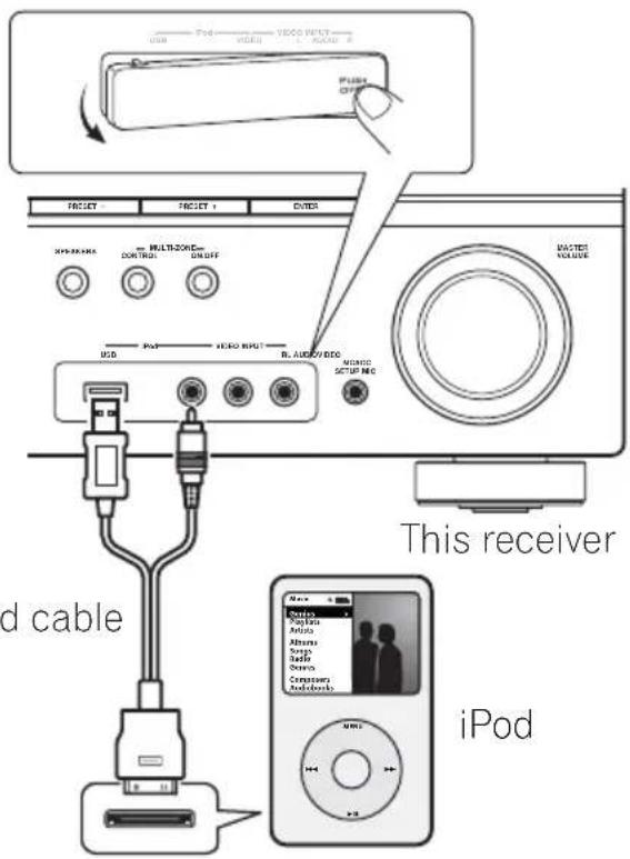
Connecting your iPod to the receiver
1 Set this receiver to the standby mode, and then use the iPod cable to connect your iPod to the iPod terminal on the front panel of this receiver.
For the cable connection, refer to also the operating instructions for iPod.

Note
1 • This system is compatible with the audio and the video of the iPod nano, iPod (fifth generation), iPod classic, iPod touch and iPhone (iPod shuffle not supported). However, that some of the functions may be restricted for some models. Note, however, compatibility may vary depending on the software version of your iPod and iPhone. Please be sure to use the latest available software version.
- iPod and iPhone are licensed for reproduction of non-copyrighted materials or materials the user is legally permitted to reproduce.
- Features such as the equalizer cannot be controlled using this receiver, and we recommend switching the equalizer off before connecting.
- Pioneer cannot under any circumstances accept responsibility for any direct or indirect loss arising from any inconvenience or loss of recorded material resulting from the iPod failure.
The front panel display shows Loading while the receiver verifies the connection and retrieves data from the iPod.
When the display shows Top Menu you're ready to play music from the iPod. ^1
- If after pressing iPod the display shows NO DEVICE, try switching off the receiver and reconnecting the iPod to the receiver.
iPod playback
To navigate songs on your iPod, you can take advantage of the OSD of your TV connected to this receiver. ^2 You can also control all operations for music in the front panel display of this receiver.
Finding what you want to play
When your iPod is connected to this receiver, you can browse songs stored on your iPod by playlist, artist, album name, song name, genre or composer, similar to using your iPod directly.
![iPod Top [ Playlists ] [ Artists ] [ Albums ] [ Songs ] [ Podcasts ] [ Genres ] [ Composers ] [ Audiobooks ] [ Shuffle Songs ] ▲▼ ENTER Return](/content/2026/02/379021/images/7c675db7e81ef81efc3fcf60d0e4606968987c0035f0d5f777e1eda1ef36ad5a.jpg)
- To return to the previous level any time, press RETURN.
- Use to move to previous/next levels
3 Continue browsing until you arrive at what you want to play, then press ▶ to start playback. ^3
Navigation through categories on your iPod looks like this:
Playlists → Songs
Artists → Albums → Songs
Albums → Songs
Songs
Podcasts
Genres → Artists → Albums → Songs
Composers → Albums → Songs
Audiobooks
Shuffle Songs

Tip
- You can play all of the songs in a particular category by selecting the All item at the top of each category list. For example, you can play all the songs by a particular artist.
Basic playback controls
The following table shows the basic playback controls for your iPod:
Button What it does
| ▶ | Press to start playback.If you start playback when something other than a song is selected, all the songs that fall into that category will play. |
| II | Pauses playback, or restarts playback when paused. |
| ENTER | Press to set the play and pause modes. |
| ◀◀/▶▶ | Press and hold during playback to start scanning. |
| I◀◀/▶▶I | Press to skip to previous/next track. |
| Press repeatedly to switch between Repeat One, Repeat All and Repeat Off. |
Note
1 The controls of your iPod (excluding the iPod touch and iPhone) will be inoperable when connected to this receiver (Pioneer shows in the iPod display).
2 • Note that non-roman characters in the title are displayed as *.
- This feature is not available for photos or video clips on your iPod.
- It is not possible to output the iPod audio to ZONE 2.
3 If you're in the song category, you can also press ENTER to start playback.
Button What it does
| × | Press repeatedly to switch between Shuffle Songs, Shuffle Albums and Shuffle Off. |
| DISPLAY | Press repeatedly to change the song playback information displayed in the front panel display. |
| ←/→ | When browsing, press to move to previous/next levels. |
| ↑/↓ | During Audiobook playback, press to switch the playback speed: Faster ↔ Normal ↔ Slower |
| TOP MENU | Press to return to the iPod Top menu screen. |
| RETURN | Press to return to the previous level. |
Watching photos and video content
To view photos or video on your iPod, since video control is not possible using this receiver, you must use the main controls of your iPod instead. ^1

Important
- To play photos or video on your iPod, you must connect the composite MONITOR OUT jack and TV.
1 Press iPod CTRL to switch to the iPod controls for photo and video playback.
The receiver controls will be unavailable while you are watching iPod videos or browsing photos.
2 Press iPod CTRL again to switch back to the receiver controls when you're done.
About iPod


"Made for iPod" means that an electronic accessory has been designed to connect specifically to iPod and has been certified by the developer to meet Apple performance standards.
"Works with iPhone" means that an electronic accessory has been designed to connect specifically to iPhone and has been certified by the developer to meet Apple performance standards.
Apple is not responsible for the operation of this device or its compliance with safety and regulatory standards.
iPod is a trademark of Apple Inc., registered in the U.S. and other countries. iPhone is a trademark of Apple Inc.
Connecting a USB device
It is possible to listen to two-channel audio ^2 using the USB interface on the front of this receiver. Connect a USB mass storage device ^3 as shown below.

Note
1 • iPod photos and video content can be viewed only when the iPod is connected to the iPod VIDEO input on the front panel.
- This feature can only be used with an iPod having video output.
2 This includes playback of WMA/MP3/MPEG-4 AAC files (except files with copy-protection or restricted playback).
3 • Compatible USB devices include external magnetic hard drives, portable flash memory (particularly keydrives) and digital audio players (MP3 players) of format FAT16/32. It is not possible to connect this receiver to a personal computer for USB playback.
- Pioneer cannot guarantee compatibility (operation and/or bus power) with all USB mass storage devices and assumes no responsibility for any loss of data that may occur when connected to this receiver.
- With large amounts of data, it may take longer for the receiver to read the contents of a USB device.
- Push down on the PUSH OPEN tab Basic playback controls
access the USB terminal.
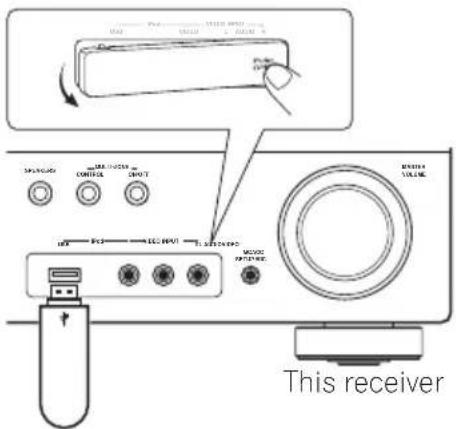
USB mass storage device
Connecting your USB device to the receiver
1 Switch on the receiver and your TV.
2 Press iPod USB on the remote control to switch the receiver to the iPod USB.
NO DEVICE appears in the OSD.
3 Connect your USB device. 1
The USB terminal is located on the front panel.
Loading appears in the OSD as this receiver starts recognizing the USB device connected. After the recognition, a playback screen appears in the OSD and playback starts automatically. ^2
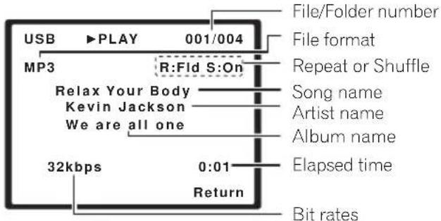
The following table shows the basic controls on the remote for USB playback. Press iPod USB to switch the remote control to the iPod USB operation mode.
| Button | What it does |
| ▶ | Starts normal playback. |
| II | Pauses/unpauses playback. |
| |◀◀/▶▶| | Press to skip to previous/next track. |
| ◀◀/▶▶ | Press and hold during playback to start scanning. |
| Press repeatedly to switch between Repeat Folder, Repeat One and Repeat All. |
| ✕ | Press repeatedly to switch between Shuffle On and Shuffle Off. |
| DISPLAY | Press repeatedly to change the song playback information displayed in the front panel display. |
| ←/→↑/↓ | During playback, press to skip to previous/next track. |
| TOP MENU | Press to return to the menu screen. |
| RETURN | Press to return to the previous level. |

Important
If a USB Error message lights in the display, try following the points below:
- Switch the receiver off, then on again.
- Reconnect the USB device with the receiver switched off.
- Select another input source (like BD), then switch back to iPod USB.
- Use a dedicated AC adapter (supplied with the device) for USB power.
For more information on error messages, see USB messages on page 68.
If this doesn't remedy the problem, it is likely your USB device is incompatible.
Note
1 Make sure the receiver is in standby when disconnecting the USB device.
2 • If the file selected cannot be played back, this receiver automatically skips to the next file playable.
- When the file currently being played back has no title assigned to it, the file name is displayed in the OSD instead; when neither the album name nor the artist name is present, the row is displayed as a blank space.
- Note that non-roman characters in the playlist are displayed as *.
- It is not possible to output the USB audio to ZONE 2.
Compressed audio compatibility
Note that although most standard bit/sampling rate combinations for compressed audio are compatible, some irregularly encoded files may not play back. The list below shows compatible formats for compressed audio files:
- MP3 (MPEG-1/2/2.5 Audio Layer 3) – Sampling rates: 8 kHz to 48 kHz; Bit rates: 8 kbps to 320 kbps (128 kbps or higher recommended); File extension: .mp3
- WMA (Windows Media Audio) – Sampling rates: 32 kHz / 44.1 kHz; Bit rates: 32 kbps to 192 kbps (128 kbps or higher recommended); File extension: .wma; WMA9 Pro and WMA lossless encoding: No
- AAC (MPEG-4 Advanced Audio Coding) – Sampling rates: 11.025 kHz to 48 kHz; Bit rates: 16 kbps to 320 kbps (128 kbps or higher recommended); File extension: .m4a; Apple lossless encoding: No
• VBR (variable bit rate) MP3/WMA/MPEG-4 AAC playback: Yes ^1
- DRM (Digital Rights Management) protection compatible: Yes (DRM-protected audio files will not play in this receiver).
About MPEG-4 AAC
Advanced Audio Coding (AAC) is at the core of the MPEG-4 AAC standard, which incorporates MPEG-2 AAC, forming the basis of the MPEG-4 audio compression technology. The file format and extension used depend on the application used to encode the AAC file. This receiver plays back AAC files encoded by iTunes® bearing the extension '.m4a'. DRM-protected files will not play, and files encoded with some versions of iTunes® may not play.
Apple and iTunes are trademarks of Apple Inc., registered in the U.S. and other countries.
About WMA

The Windows Media logo printed on the box indicates that this receiver can playback Windows Media Audio content.
WMA is an acronym for Windows Media Audio and refers to an audio compression technology developed by Microsoft Corporation. This receiver plays back WMA files encoded using Windows Media ^® Player bearing the extension '.wma'. Note that DRM-protected files will not play, and files encoded with some versions of Windows Media ^® Player may not play.
Windows Media, and the Windows logo are trademarks or registered trademarks of Microsoft Corporation in the United States and/or other countries.
Using SIRIUS Radio
With SIRIUS you get The Best Radio on Radio™ with all your favorite entertainment including 100 % commercial-free music, plus superior sports coverage, uncensored talk and comedy, world-class entertainment, news, weather and more for your car, home or office. For more information visit sirius.com or siriuscanada.ca Sirius is available in the US for subscribers with addresses in the continental US and is available in Canada for subscribers with a Canadian address. Required subscription plus compatible SIRIUS tuner and antenna are required and sold separately. SIRIUS Programming is subject to change. Visit http://www.sirius.com for the most complete and up-to-date channel lineup and product information.

Note
1 Note that in some cases playback time will not be displayed correctly.
Connecting your SiriusConnect™ Tuner
To receive SIRIUS Satellite Radio broadcasts, you will need to activate your SiriusConnect tuner. ^1
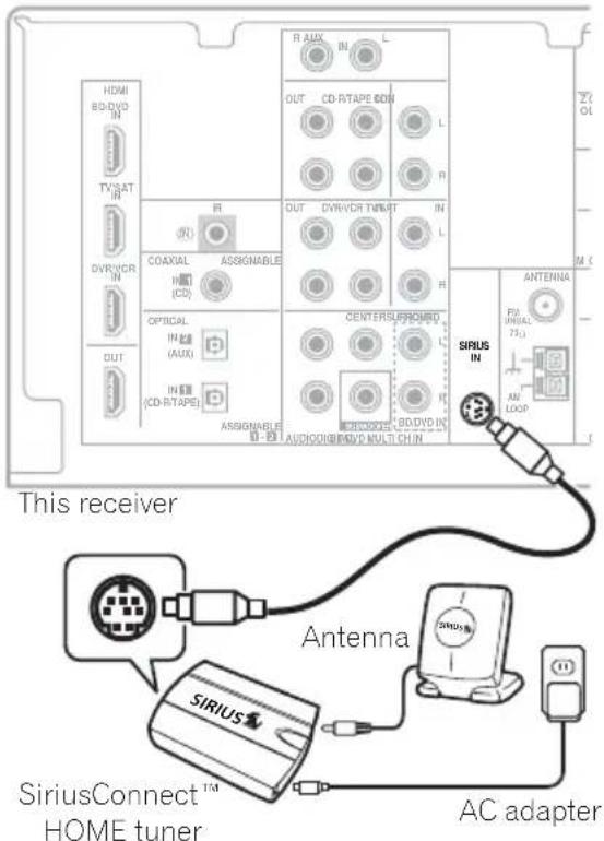
1 Connect a SiriusConnect tuner to the SIRIUS IN jack on the rear of this receiver.
You will also need to connect the antenna and AC adapter to the SiriusConnect tuner.
For best reception, you may need to move the SiriusConnect tuner antenna near a window (refer to the manual for the SiriusConnect Home tuner for antenna placement recommendations).
- If after pressing SIRIUS the display shows ANTENNA ERROR, try disconnecting the antenna and reconnecting. ^2 If the display shows CHECK SIRIUS TUNER, check the connection of the AC adapter and this receiver to the SiriusConnect tuner.
Listening to SIRIUS Radio
After connecting, you will be able to use this receiver to select channels using the front panel display.
Selecting channels and browsing by genre
Use the front panel display to select channels. You can select channels from your favorite genre. ^3
- Press ↑/↓ to select the channel. In the next 2 seconds, the radio broadcast is automatically tuned in.
- To select a channel from your favorite genre, press CATEGORY and use / to select a genre, and then use / and ENTER to select a channel from the selected genre. ^4
- To cancel and exit any time, press RETURN.

Tip
- You can select channels directly by pressing D.ACCESS then the three-digit channel number.
- You can press DISPLAY to change SIRIUS Radio information in the front panel display.
- The currently selected channel is automatically chosen (without pressing ENTER) after 2 seconds.
Note
1 In order to activate your radio subscription, you will need the SIRIUS ID (SID) which uniquely identifies your tuner. The SID may be found on a sticker located on the packaging, or on the bottom of the tuner itself. The label will have a printed 12-digit SID number. When you have located the SID, write it down in the space provided near the end of this manual. Connect SIRIUS on the internet at: https://activate.siriusradio.com
Follow the prompts to activate your subscription, or you can also call SIRIUS toll-free at 1-888-539-SIRIUS (1-888-539-7474).
2 You can check the strength of reception in Using the SIRIUS Menu on page 64.
3 You can, however, use just the front panel display to do everything if you prefer.
4 Select SR000 (SIRIUS ID) from the front panel display to check the Radio ID of the SIRIUS Connect tuner.
Saving channel presets
This receiver can memorize up to 30 channels, stored.
1 Select the channel you want to memorize.
See Selecting channels and browsing by genre above.
2 Press T.EDIT.
The display shows a blinking memory number.
3 Press ←/→ to select the channel preset you want.
You can also use the number buttons to select a preset.
4 Press ENTER.
After pressing ENTER, the preset number stop blinking and the receiver stores the SIRIUS channel.
Listening to channel presets
You will need to have some presets stored to do this.
1 Press ←/→ to select the channel preset you want.
- You can also use the number buttons on the remote control to recall the channel preset.
The SIRIUS Menu provides additional SIRIUS Radio features.
Choose between the following menu items:
- ALL CHANNEL SKIP CLEAR – Clear the channel skip function set by the SiriusConnect tuner. If the channel skip function is not cleared here, not all channels are displayed because this receiver stores the channels set for skipping in the SiriusConnect tuner.
- PARENTAL LOCK – Use ↑/↓ and ENTER to select channels you would like to place under parental lock. Channels put under parental lock are not displayed in the Channel Guide, but may be accessed by directly inputting their channel number and providing the parental lock password.
- PASSWORD SET – Set the parental lock password.
3 When you're finished press TOP MENU to return to the reception display.

Tip
- You can reset the channel presets, parental lock and Password Set in Resetting the main unit on page 69.
Connecting an IR receiver
If you keep your stereo components in a closed cabinet or shelving unit, or you wish to use the sub zone remote control in another zone, you can use an optional IR receiver (such as a Niles or Xantech unit) to control your system instead of the remote sensor on the front panel of this receiver. ^1
1 Connect the IR receiver sensor to the IR IN jack on the rear of this receiver.
For more information on connecting the IR receiver, see the Installation Instructions for the IR Receiver.
Note
1 • Remote operation may not be possible if direct light from a strong fluorescent lamp is shining on the IR receiver remote sensor window.
- Note that other manufacturers may not use the IR terminology. Refer to the manual that came with your component to check for IR compatibility.
- If using two remote controls (at the same time), the IR receiver's remote sensor takes priority over the remote sensor on the front panel.
Chapter 12:
Troubleshooting
Incorrect operations are often mistaken for trouble and malfunctions. If you think that there is something wrong with this component, check the points below. Take a look at the other components and electrical appliances being used, because sometimes the problem may lie there. If the trouble isn't sorted out even after going through the checks below, ask your nearest Pioneer authorized independent service company to carry out repair work.
- If the unit does not operate normally due to external effects such as static electricity disconnect the power plug from the outlet and insert again to return to normal operating conditions.
| Problem Remedy |
| The power does not turn on. • Disconnect the power plug from the outlet, and insert again.• Make sure there are no loose strands of speaker wire touching the rear panel. This could cause the receiver to shut off automatically. |
| The receiver suddenly switches off. | • After about a minute (you won't be able to switch the unit on during this time), switch the receiver back on. If the message persists, call a Pioneer authorized independent service company. |
| No sound is output when a function is selected. | • Make sure the component is connected correctly (refer to Connecting up on page 12).• Press MUTE on the remote control to turn muting off.• Press SPEAKERS to select the proper speaker set (see Switching the speaker system on page 25).• Press SIGNAL SEL to select the proper input signal (see Choosing the input signal on page 40). |
| No image is output when a function is selected. | • Make sure the component is connected correctly (refer to Connecting up on page 12).• Select the correct component (use the MULTI CONTROL buttons).• Check The Input Assign menu on page 44 to make sure you're assigned the correct input.• The video input selected on the TV monitor is incorrect. Refer to the instruction manual supplied with the TV. |
| No sound from subwoofer. • Make sure the subwoofer is switched on.• If the subwoofer has a volume knob, make sure it's turned up.• The Dolby Digital or DTS source you are listening to may not have an LFE channel.• Switch the subwoofer setting in Speaker Setting on page 42 to YES or PLUS.• Switch the LFE ATT (LFE Attenuate) on page 39 to LFEATT 0 or LFEATT 10. |
| No sound from surround or center speakers. | • Connect the speakers properly (refer to page 22).• Refer to Speaker Setting on page 42 to check the speaker settings.• Refer to Channel Level on page 43 to check the speaker levels. |
| The PHASE CONTROL feature doesn't seem to have an audible effect. | • If applicable, check that the lowpass filter switch on your subwoofer is off, or the lowpass cutoff is set to the highest frequency setting. If there is a PHASE setting on your subwoofer, set it to 0^ (or depending on the subwoofer, the setting where you think it has the best overall effect on the sound).• Make sure the speaker distance setting is correct for all speakers (see Speaker Distance on page 44). |
Problem Remedy
| Considerable noise in radio broadcasts. | Connect the antenna (page 20) and adjust the position for best reception.Route any loose cables away from the antenna terminals and wires.Fully extend the FM wire antenna, position for best reception, and secure to a wall (or connect an outdoor FM antenna).Connect an additional internal or external AM antenna (page 21).Turn off equipment causing interference or move it away from the receiver (or move antennas farther away from equipment causing noise). |
| Broadcast stations cannot be selected automatically. | Connect an outdoor antenna (refer to page 21). |
| Noise during playback of a cassette deck. | Move the cassette deck away from your receiver, until the noise disappears. |
| Sound is produced from other components, but not from LD or DVD player. | Set the SIGNAL SEL to HDMI, C1/O1/O2 (DIGITAL) or A (analog) according to the type of connections made (refer to page 40).Set the digital input settings correctly (refer to page 44).Make digital connections (refer to page 14) and set the SIGNAL SEL to C1/O1/O2 (DIGITAL) (refer to page 40).Refer to the instruction manual supplied with the DVD player. |
| No sound is output or a noise is output when software with DTS is played back. | Set the digital volume level of the player to full, or to the neutral position.Make sure the player's settings are correct and/or the DTS signal out is on. Refer to the instruction manual supplied with the DVD player.Set the input signal type to C1/O1/O2 (DIGITAL) (see Choosing the input signal on page 40). |
| During a playback search, noise is output from a DTS compatible CD player. | This is not a malfunction, but be sure to turn the volume down to prevent the output of loud noise from your speakers. |
| Everything seems to be set up correctly, but the playback sound is odd. | Check that the positive/negative speaker terminals on the receiver are matched with the corresponding terminals on the speakers (see Connecting the speakers on page 22). |
| There seems to be a time lag between the speakers and the output of the subwoofer. | See Automatically setting up for surround sound (MCACC) on page 9 to set up your system again using MCACC (this will automatically compensate for a delay in the subwoofer output). |
| After using the Auto MCACC Setup, the speaker size setting (LARGE or SMALL) is incorrect. | Low-frequency noise could have been caused by an air conditioner or motor. Switch off all appliances in the room and rerun the Auto MCACC Setup. |
| Can't operate the remote control. | Replace the batteries (refer to page 6).Operate within 7 m (23 ft.), 30° of the remote sensor (refer to page 27).Remove the obstacle or operate from another position.Avoid exposing the remote sensor on the front panel to direct light. |
| The display is dark or off. | Press DIMMER on the control repeatedly to return to the default. |
HDMI
| Symptom Remedy |
| No picture or sound. | ·If the problem still persists when connecting your HDMI component directly to your monitor, please consult the component or monitor manual or contact the manufacturer for support. |
| No picture. | ·Depending in the output settings of the source component, it may be outputting a video format that can't be displayed. Change the output settings of the source, or connect using the component or composite jacks.·This receiver is HDCP-compatible. Check that the components you are connecting are also HDCP-compatible. If they are not, please connect them using the component or composite video jacks.·Depending on the connected source component, it's possible that it will not work with this receiver (even if it is HDCP-compatible). In this case, connect using the component or composite video jacks between source and receiver.·If video images do not appear on your TV or flat panel TV, try adjusting the resolution, DeepColor or other setting for your component.·To output signals in DeepColor, use an HDMI cable (High Speed HDMI TM Cable) to connect this receiver to a component or TV with the DeepColor feature. |
| OSD does not appear. | ·The OSD will not appear if you have connected using the HDMI output to your TV. Use component or composite connections when setting up the system. |
| No sound, or sound suddenly ceases. | ·If you've made separate connections for audio, make sure you have assigned the analog/digital jack(s) to the corresponding HDMI input for the component.·Check the audio output settings of the source component.·Check that the Audio Parameter setting is set to HDMI AMP/THRU (refer to page 39).·If the component is a DVI device, use a separate connection for the audio. |
There are cases where you may not be able to route HDMI signals through this receiver (this depends on the HDMI equipped component you are connecting-check with the manufacturer for HDMI compatibility information).
If you aren't receiving HDMI signals properly through this receiver (from your component), please try the following configuration when connecting up.
Configuration ^1
Connect your HDMI-equipped component directly to the display using an HDMI cable. Then use the most convenient connection (digital is recommended) for sending audio to the receiver. See the operating instructions for more on audio connections. Set the display volume to minimum when using this configuration.
Note
- If your display only has one HDMI terminal, you can only receive HDMI video from the connected component.
- Depending on the component, audio output may be limited to the number of channels available from the connected display unit (for example audio output is reduced to 2 channels for a monitor with stereo audio limitations).
- If you want to switch the input source, you'll have to switch functions on both the receiver and your display unit.
- Since the sound is muted on the display when using the HDMI connection, you must adjust the volume on the display every time you switch input sources.
iPod messages
| Symptom Cause Action |
| iPod/USB Error 1(I/U ERR1) | There is a problem with the signal path from the iPod to the receiver. | Switch off the receiver and reconnect the iPod to the receiver. If this doesn’t seem to work, try resetting your iPod. |
| iPod/USB Error 2(I/U ERR2) | The software version being used with the iPod needs to be updated. | Update the software being used with the iPod (please use the latest iPod software versions later than the iPod updater 2004-10-20). |
| An iPod not supported by this receiver is connected. | Connect the iPod supported by this receiver. |
| iPod/USB Error 3(I/U ERR3) | When there is no response from the iPod. Update the iPod software to the latest version. If this doesn’t seem to work, try resetting your iPod. |
| No Track | When there are no tracks in the category selected on the iPod. | Select a different category. |
USB messages
| Symptom Cause Action |
| iPod/USB Error 1(I/U ERR1) | There is a problem with the signal path from the USB to the receiver. | Switch off the receiver and reconnect the USB to the receiver. |
| iPod/USB Error 3(I/U ERR3) | When there is no response from the USB. Switch off the receiver and reconnect the USB to the receiver. |
| iPod/USB Error 4(I/U ERR4) | The power requirements of the USB device are too high for this receiver. | Switch off the receiver and reconnect the USB to the receiver. |
SIRIUS radio messages
| Symptom Cause Action |
| ANTENNA Antenna is not properly connected. Check that the antenna cable is attached securely. |
| CHECK SIRIUS TUNER | SIRIUS Connect tuner is not properly connected | Check that the 8 pin mini DIN cable and AC Adapter are attached securely. |
| LINKING The SIRIUS signal is too weak at the current location. There is no SIRIUS signal or the SiriusConnect Tuner is connected. | n/a |
| UPDT ***% Unit is updating subscription. Wait until the encryption code has been updated. |
| UPDATING | Unit is updating channels. | Wait until the encryption code has been updated. |
| INVALID CHANNEL | Selected channel is not available/does not exist. | Select another channel. |
Resetting the main unit
Use this procedure to reset all the receiver's settings to the factory default. Use the front panel controls to do this.
1 Switch the receiver into standby.
2 While holding down the BAND button, press and hold the ⏻ STANDBY/ON button for about two seconds.
3 When you see RESET? appear in the display, press 'AUTO SURROUND/STREAM DIRECT'.
OK? shows in the display.
4 Press ' STEREO/A.L.C.' to confirm.
OK appears in the display to indicate that the receiver has been reset to the factory settings.
Specifications
Amplifier section
Continuous average power output of 80 watts* per channel, min., at 8 ohms, from 20 Hz to 20 000 Hz with no more than 0.2 %** total harmonic distortion.
Front (stereo)....80 W + 80 W
Power output (1 kHz, 8 Ω, 0.05 %)
110 W per channel
Guaranteed speaker impedance
FRONT:A, B 6 Ω to 16 Ω
FRONT:A+B....12Ω to 16Ω
SURROUND, CENTER ..... 6 Ω to 16 Ω
* Measured pursuant to the Federal Trade Commission's Trade Regulation rule on Power Output Claims for Amplifiers
** Measured by Audio Spectrum Analyzer
Audio Section
Input (Sensitivity/Impedance)
LINE 200 mV/47 kΩ
Output (Level/Impedance)
REC 200 mV/330 Ω
ZONE 2....200 mV/1 kΩ
Signal-to-Noise Ratio
(IHF, short circuited, A network)
LINE 98 dB
Signal-to-Noise Ratio [EIA, at 1 W (1 kHz)]
LINE 79 dB
Tuner Section
Frequency Range (FM) . . . 87.5 MHz to 108 MHz
Antenna Input (FM) ..... 75 Ω unbalanced
Frequency Range (AM) . . . 530 kHz to 1700 kHz
Antenna (AM) ..... Loop antenna
Video Section
Signal level
Composite.... 1 Vp-p (75 Ω)
Component Video.....Y: 1.0 Vp-p (75 Ω)
Corresponding maximum resolution
Component Video....1080p (1125p)
Digital In/Out Section
HDMI terminal ..... 19-pin (Not DVI)
HDMI output type 5 V, 100 mA
USB terminal ..... USB2.0 Full Speed (Type A)
iPod terminal. . . . USB, and Video (Composite)
SIRIUS antenna cable .... 8-pin mini DIN cable
Integrated control section
Control (IR) terminal ... ∅ 3.5 Mini-jack (MONO)
IR signal..... High Active (High Level : 2.0 V)
Miscellaneous
Power Requirements ..... AC 120 V, 60 Hz
Power Consumption....250 W
In standby....0.65 W
Dimensions
16^9/16 in. (W) × 6^1/4 in. (H) × 13^3/_4 in. (D)
Weight (without package) 9 kg (19 lb 14 oz)
Furnished Parts
Microphone (for Auto MCACC setup).....1
Remote control 1
Dry cell batteries (AAA size IEC R03) ..... 2
AM loop antenna 1
FM wire antenna....1
iPod cable....1
These operating instructions

Note
- Specifications and the design are subject to possible modifications without notice, due to improvements.


Dear Customer:
Selecting fine audio equipment such as the unit you've just purchased is only the start of your musical enjoyment. Now it's time to consider how you can maximize the fun and excitement your equipment offers. This manufacturer and the Electronic Industries Association's Consumer Electronics Group want you to get the most out of your equipment by playing it at a safe level. One that lets the sound come through loud and clear without annoying blaring or distortion-and, most importantly, without affecting your sensitive hearing.
Sound can be deceiving. Over time your hearing "comfort level" adapts to higher volumes of sound. So what sounds "normal" can actually be loud and harmful to your hearing. Guard against this by setting your equipment at a safe level BEFORE your hearing adapts.
To establish a safe level:
- Start your volume control at a low setting.
- Slowly increase the sound until you can hear it comfortably and clearly, and without distortion.
Once you have established a comfortable sound level:
- Set the dial and leave it there.
Taking a minute to do this now will help to prevent hearing damage or loss in the future. After all, we want you listening for a lifetime.
We Want You Listening For A Lifetime
Used wisely, your new sound equipment will provide a lifetime of fun and enjoyment. Since hearing damage from loud noise is often undetectable until it is too late, this manufacturer and the Electronic Industries Association's Consumer Electronics Group recommend you avoid prolonged exposure to excessive noise. This list of sound levels is included for your protection.
Decibel
Level Example
30 Quiet library, soft whispers
40 Living room, refrigerator, bedroom away from traffic
50 Light traffic, normal conversation, quiet office
60 Air conditioner at 20 feet, sewing machine
70 Vacuum cleaner, hair dryer, noisy restaurant
80 Average city traffic, garbage disposals, alarm clock at two feet.
THE FOLLOWING NOISES CAN BE DANGEROUS UNDER CONSTANT EXPOSURE
90 Subway, motorcycle, truck traffic, lawn mower
100 Garbage truck, chain saw, pneumatic drill
120 Rock band concert in front of speakers, thunderclap
140 Gunshot blast, jet plane
180 Rocket launching pad
Information courtesy of the Deafness Research Foundation.


S001 En
Power cord caution
Handle the power cord by the plug. Do not pull out the plug by tugging the cord and never touch the power cord when your hands are wet as this could cause a short circuit or an electric shock. Do not place the unit, a piece of furniture, etc., on the power cord, or pinch the cord. Never make a knot in the cord or tie it with other cords. The power cords should be routed such that they are not likely to be stepped on. A damaged power cord can cause a fire or give you an electrical shock. Check the power cord once in a while. When you find it damaged, ask your nearest Pioneer authorized service center or your dealer for a replacement.
Cleaning the unit
- Use a polishing cloth or dry cloth to wipe off dust and dirt.
- When the surface is dirty, wipe with a soft cloth dipped in some neutral cleanser diluted five or six times with water, and wrung out well, and then wipe again with a dry cloth. Do not use furniture wax or cleansers.
- Never use thinners, benzine, insecticide sprays or other chemicals on or near this unit, since these will corrode the surface.
AVERTISSEMENT
This Class B digital apparatus complies with Canadian ICES-003.
natural_image
Diagram showing two views of a remote control panel with battery and switch mechanism (no text or symbols)

Attention
natural_image
Line drawing of a rectangular electronic device with a coiled cable and internal components (no text or symbols)

Important
natural_image
Pure mechanical component diagram without any text, numbers, or symbols
Câble HDMI
flowchart
graph TD
    A["Wireless Cable"] --> B["Switch 1: Cable to Computer"]
    B --> C["Switch 2: Cable to Antenna"]
    C --> D["Switch 3: Cable to PC"]
    D --> E["Switch 4: Cable to Cable"]
    style A fill:#f9f,stroke:#333
    style B fill:#ccf,stroke:#333
    style C fill:#cfc,stroke:#333
    style D fill:#fcc,stroke:#333
    style E fill:#cff,stroke:#333
13 Prise MCACC SETUP MIC
Affichage
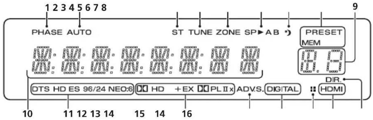
flowchart
graph TD
    A["PHASE AUTO"] --> B["ST TUNE ZONE SP→AB"]
    B --> C["PRESET MEM"]
    C --> D["HDMI"]
    D --> E["DIR."]
    E --> F["DTS HD ES 96/24 NEO:6"]
    F --> G["HD + EX PLIIx"]
    G --> H["ADV.S. DIGITAL"]
    H --> I["HDMI"]
    style A fill:#f9f,stroke:#333
    style B fill:#ccf,stroke:#333
    style C fill:#cfc,stroke:#333
    style D fill:#fcc,stroke:#333
    style E fill:#ffc,stroke:#333
    style F fill:#cff,stroke:#333
    style G fill:#ffc,stroke:#333
    style H fill:#cfc,stroke:#333
    style I fill:#fcc,stroke:#333
1 PHASE
flowchart
graph TD
    A["FL"] --> B["FW"]
    B --> C["C"]
    C --> D["SL"]
    D --> E["Square"]
    D --> F["Square"]
    D --> G["Square"]
    D --> H["Square"]
    D --> I["Square"]
    D --> J["Square"]
    D --> K["Square"]
    D --> L["Square"]
    D --> M["Square"]
    D --> N["Square"]
    D --> O["Square"]
    D --> P["Square"]
    D --> Q["Square"]
    D --> R["Square"]
    D --> S["Square"]
    D --> T["Square"]
    D --> U["Square"]
    D --> V["Square"]
    D --> W["Square"]
    D --> X["Square"]
    D --> Y["Square"]
    D --> Z["Square"]
White Westinghouse
0023
Yamaha 0004, 0005, 0006, 0100
Zenith 0001, 0004, 0011, 0015, 0099
VCR
Fabricant Code
ABS 1017
Adventura 1005
Aiwa 1005
Alienware 1017
American High 1004
Asha 1002
Audio Dynamics 1000
Audiovox 1003
Bang & Olufsen 1032
Beaumark 1002
Bell & Howell 1001
Calix 1003
Candle 1002.1003
Canon 1004
Citizen 1002, 1003
Colortyme 1000
Craig 1002, 1003
Curtis Mathes 1000, 1002, 1004
Cybernex 1002
CyberPower 1017
Daewoo 1005
DBX 1000
Dell 1017
DIRECTV 1016, 1020, 1022, 1023, 1024, 1027, 1030, 1031
Dish Network 1029
Dishpro 1029
Durabrand 1018
Dynatech 1005
Echostar 1029
Electrohome 1003
Electrophonic 1003
Emerson 1003, 1004, 1005
Expressvu 1029
Fisher 1001
Fuji 1004
Funai 1005
Garrard 1005
Gateway 1017
GE 1002, 1004
GOI 1029
Goldstar 1000, 1003
Gradiente 1005
Harley Davidson 1005
Harman/Kardon 1000
Headquarter 1001
Hewlett Packard 1017
HNS 1016
Howard Computers 1017
HP 1017
HTS 1029
Hughes Network Systems 1016, 1020, 1022, 1023, 1024
Humax 1016, 1020
Hush 1017
iBUYPOWER 1017
Instant Replay 1004
JC Penney 1000, 1001,
1002, 1003, 1004
JCL 1004
JVC 1000, 1001, 1020, 1029
Kenwood 1000, 1001
Kodak 1003, 1004
LG 1003
Linksys 1017
Lloyd's 1005
LXI 1003
Magnavox 1004, 1018
Magnin 1003
Marantz 1000, 1001, 1004
Marta 1003
Matsushita 1004
Media Center PC 1017
MEI 1004
Memorex 1001, 1002,
1003, 1004, 1005, 1018,
1019
MGN Technology 1002
Microsoft 1017
Mind 1017
Mitsubishi 1010
Motorola 1004
MTC 1002
Multitech 1002, 1005
NEC 1000, 1001
Nikko 1003
Niveus Media 1017
Noblex 1002
Northgate 1017
Olympus 1004
Optimus 1003
Orion 1014, 1019
Pioneer 1120
Panasonic 1004, 1008
Philco 1004
Philips 1004, 1011, 1016, 1020, 1022, 1023, 1024, 1025
Philips Magnavox 1011
Pilot 1003
Proscan 1030
Pulsar 1018
Quarter 1001
Quartz 1001
Quasar 1004
Radio Shack 1003
Radio Shack/Realistic
1001, 1002, 1003, 1004,
1005
Radix 1003
Randex 1003
RCA 1002, 1004, 1007,
1016, 1020, 1022, 1030,
1031
Realistic 1001, 1002, 1003, 1004, 1005
ReplayTV 1026
Ricavision 1017
Runco 1018
Samsung 1002, 1016, 1022, 1024
Sanky 1018
Sansui 1014, 1019
Sanyo 1001, 1002
Sears 1001, 1003, 1004
Sharp 1012
Shogun 1002
Singer 1004
Sonic Blue 1026
Sony 1006, 1009, 1017, 1021
Stack 1017
STS 1004
Sylvania 1004, 1005
Symphonic 1005
Systemax 1017
Tagar Systems 1017
Tandy 1001
Tashiko 1003
Teac 1005
Technics 1004
Teknika 1003, 1004, 1005
Tivo 1016, 1020, 1021, 1022, 1025
TMK 1002
Toshiba 1015, 1017, 1028
Totevision 1002, 1003
Touch 1017
UltimateTV 1031
Unitech 1002
Vector Research 1000
Video Concepts 1000
Videosonic 1002
Viewsonic 1017
Voodoo 1017
Wards 1002, 1003, 1004, 1005
XR-1000 1004, 1005
Yamaha 1000, 1001
Zenith 1013. 1018
ZT Group 1017
Chapitre 11:
Autres raccordements

Attention
Playlists → Songs
Artists → Albums → Songs
Albums → Songs
Songs
Podcasts
Genres → Artists → Albums → Songs
Composers → Albums → Songs
Audiobooks
Shuffle Songs

Astuce
Publication de Pioneer Corporation.
© 2008 Pioneer Corporation.
natural_image
Diagram showing two views of a remote control device with labeled parts (no text or symbols present)

Precaución
natural_image
Line drawing of a rectangular electronic device with a curved cable and internal components, no text or symbols present.

Importante
natural_image
Diagram of a connector with threaded body and arrow indicating direction (no text or symbols)
Cable HDMI
6 Dial MASTER VOLUME
7 Conector PHONES
13 Conector MCACC SETUP MIC
Pantalla
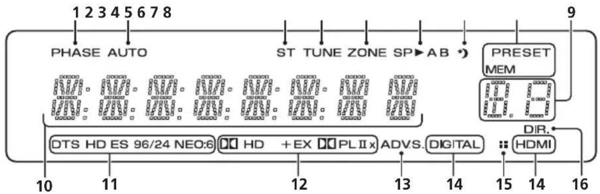
flowchart
graph TD
    A["PHASE AUTO"] --> B["ST TUNE ZONE SP→AB"]
    B --> C["PRESET MEM"]
    C --> D["DIR."]
    D --> E["HDMI"]
    subgraph Inputs
        F["10"] --> G["11"]
        H["12"] --> I["13"]
        J["14"] --> K["15"]
        L["16"]
    end
    F --> M["DTS HD ES 96/24 NEO:6"]
    G --> N["HD + EX PL II x"]
    H --> O["ADV.S. DIGITAL"]
    I --> P["..."]
    J --> Q["..."]
    K --> R["..."]
    L --> S["..."]
    M --> T["12"]
    N --> U["13"]
    O --> V["14"]
    P --> W["15"]
    Q --> X["16"]
    R --> Y["15"]
    S --> Z["14"]
    T --> AA["16"]
    U --> AB["15"]
    V --> AC["14"]
    W --> AD["16"]
1 PHASE
Uso de Front Stage Surround Advance
Radio Shack/Realistic
White Westinghouse
0023
Yamaha 0004, 0005, 0006, 0100
Zenith 0001, 0004, 0011, 0015, 0099
VCR
Fabricante Código
ABS 1017
Adventura 1005
Aiwa 1005
Alienware 1017
American High 1004
Asha 1002
Audio Dynamics 1000
Audiovox 1003
Bang & Olufsen 1032
Beaumark 1002
Bell & Howell 1001
Calix 1003
Candle 1002, 1003
Canon 1004
Citizen 1002, 1003
Colortyme 1000
Craig 1002, 1003
Curtis Mathes 1000, 1002, 1004
Cybernex 1002
CyberPower 1017
Daewoo 1005
DBX 1000
Dell 1017
DIRECTV 1016, 1020, 1022, 1023, 1024, 1027, 1030, 1031
Dish Network 1029
Dishpro 1029
Durabrand 1018
Dynatech 1005
Echostar 1029
Electrohome 1003
Electrophonic 1003
Emerson 1003, 1004, 1005
Expressvu 1029
Fisher 1001
Fuji 1004
Funai 1005
Garrard 1005
Gateway 1017
GE 1002, 1004
GOI 1029
Goldstar 1000, 1003
Gradiente 1005
Harley Davidson 1005
Harman/Kardon 1000
Headquarter 1001
Hewlett Packard 1017
HNS 1016
Howard Computers 1017
HP 1017
HTS 1029
Hughes Network
Systems 1016, 1020, 1022, 1023, 1024
Humax 1016, 1020
Hush 1017
iBUYPOWER 1017
Instant Replay 1004
JC Penney 1000, 1001, 1002, 1003, 1004
JCL 1004
JVC 1000, 1001, 1020, 1029
Kenwood 1000, 1001
Kodak 1003. 1004
LG 1003
Linksys 1017
Lloyd's 1005
LXI 1003
Magnavox 1004, 1018
Magnin 1003
Marantz 1000, 1001, 1004
Marta 1003
Matsushita 1004
Media Center PC 1017
MEI 1004
Memorex 1001, 1002,
1003, 1004, 1005, 1018,
1019
MGN Technology 1002
Microsoft 1017
Mind 1017
Mitsubishi 1010
Motorola 1004
MTC 1002
Multitech 1002, 1005
NEC 1000, 1001
Nikko 1003
Niveus Media 1017
Noblex 1002
Northgate 1017
Olympus 1004
Optimus 1003
Orion 1014, 1019
Pioneer 1120
Panasonic 1004, 1008
Philco 1004
Philips 1004, 1011, 1016, 1020, 1022, 1023, 1024, 1025
Philips Magnavox 1011
Pilot 1003
Proscan 1030
Pulsar 1018
Quarter 1001
Quartz 1001
Quasar 1004
Radio Shack 1003
Radio Shack/Realistic
1001, 1002, 1003, 1004,
1005
Radix 1003
Randex 1003
RCA 1002, 1004, 1007,
1016, 1020, 1022, 1030,
1031
Realistic 1001, 1002, 1003, 1004, 1005
ReplayTV 1026
Ricavision 1017
Runco 1018
Samsung 1002, 1016, 1022, 1024
Sanky 1018
Sansui 1014, 1019
Sanyo 1001, 1002
Sears 1001, 1003, 1004
Sharp 1012
Shogun 1002
Singer 1004
Sonic Blue 1026
Sony 1006, 1009, 1017, 1021
Stack 1017
STS 1004
Sylvania 1004, 1005
Symphonic 1005
Systemax 1017
Tagar Systems 1017
Tandy 1001
Tashiko 1003
Teac 1005
Technics 1004
Playlists → Songs
Artists → Albums → Songs
Albums → Songs
Songs
Podcasts
Genres → Artists → Albums → Songs
Composers → Albums → Songs
Audiobooks
Shuffle Songs

Sugerencia
PIONEER ELECTRONICS (USA) INC.
PIONEER ELECTRONICS OF CANADA, INC.
LIMITED WARRANTY
WARRANTY VALID ONLY IN COUNTRY OF PRODUCT PURCHASE
WARRANTY
Pioneer Electronics (USA) Inc. (PUSA), and Pioneer Electronics Of Canada, Inc. (POC), warrant that products distributed by PUSA in the U.S.A., and by POC in Canada that fail to function properly under normal use due to a manufacturing defect when installed and operated according to the owner's manual enclosed with the unit will be repaired or replaced with a unit of comparable value, at the option of PUSA or POC, without charge to you for parts or actual repair work. Parts supplied under this warranty may be new or rebuilt at the option of PUSA or POC.
THIS LIMITED WARRANTY APPLIES TO THE ORIGINAL OR ANY SUBSEQUENT OWNER OF THIS PIONEER PRODUCT DURING THE WARRANTY PERIOD PROVIDED THE PRODUCT WAS PURCHASED FROM AN AUTHORIZED PIONEER DISTRIBUTOR/DEALER IN THE U.S.A. OR CANADA. YOU WILL BE REQUIRED TO PROVIDE A SALES RECEIPT OR OTHER VALID PROOF OF PURCHASE SHOWING THE DATE OF ORIGINAL PURCHASE OR, IF RENTED, YOUR RENTAL CONTRACT SHOWING THE PLACE AND DATE OF FIRST RENTAL. IN THE EVENT SERVICE IS REQUIRED, THE PRODUCT MUST BE DELIVERED WITHIN THE WARRANTY PERIOD, TRANSPORTATION PREPAID, ONLY FROM WITHIN THE COUNTRY OF PURCHASE AS EXPLAINED IN THIS DOCUMENT. YOU WILL BE RESPONSIBLE FOR REMOVAL AND INSTALLATION OF THE PRODUCT. PUSA OR POC, AS APPROPRIATE, WILL PAY TO RETURN THE REPAIRED OR REPLACEMENT PRODUCT TO YOU WITHIN THE COUNTRY OF PURCHASE.
PRODUCT WARRANTY PERIOD
Home Audio and Video
Microphones, Headphones, Phono Cartridges and Styluses
Parts Labor
1 Year 1 Year
90 Days 90 Days
Shorter limited warranty periods apply to some models. Please refer to the limited warranty document enclosed with the product for a definitive statement of the warranty period. The warranty period for retail customers who rent the product commences upon the date product is first put into use (a) during the rental period or (b) retail sale, whichever occurs first.
WHAT IS NOT COVERED
IF THIS PRODUCT WAS PURCHASED FROM AN UNAUTHORIZED DISTRIBUTOR, THERE ARE NO WARRANTIES, EXPRESS OR IMPLIED, INCLUDING THE IMPLIED WARRANTY OF MERCHANTABILITY AND THE IMPLIED WARRANTY OF FITNESS FOR A PARTICULAR PURPOSE AND THIS PRODUCT IS SOLD STRICTLY "AS IS" AND "WITH ALL FAULTS". PIONEER SHALL NOT BE LIABLE FOR ANY CONSEQUENTIAL AND/OR INCIDENTAL DAMAGES.
PIONEER DOES NOT WARRANT ANY PRODUCT LISTED ABOVE WHEN IT IS USED IN A TRADE OR BUSINESS OR IN ANY INDUSTRIAL OR COMMERCIAL APPLICATION. THIS WARRANTY DOES NOT APPLY IF THE PRODUCT HAS BEEN SUBJECTED TO POWER IN EXCESS OF ITS PUBLISHED POWER RATING.
THIS WARRANTY DOES NOT COVER TELEVISION OR DISPLAY SCREENS DAMAGED BY STATIC, NON-MOVING, IMAGES APPLIED FOR LENGTHY PERIODS (BURN-IN).
THIS WARRANTY DOES NOT COVER THE CABINET OR ANY APPEARANCE ITEM, USER ATTACHED ANTENNA, ANY DAMAGE TO RECORDS OR RECORDING TAPES OR DISCS, ANY DAMAGE TO THE PRODUCT RESULTING FROM ALTERATIONS, MODIFICATIONS NOT AUTHORIZED IN WRITING BY PIONEER, ACCIDENT, MISUSE OR ABUSE, DAMAGE DUE TO LIGHTNING OR TO POWERSURGES, SUBSEQUENT DAMAGE FROM LEAKING, DAMAGE FROM INOPERATIVE BATTERIES, OR THE USE OF BATTERIES NOT CONFORMING TO THOSE SPECIFIED IN THE OWNER'S MANUAL.
THIS WARRANTY DOES NOT COVER THE COST OF PARTS OR LABOR WHICH WOULD BE OTHERWISE PROVIDED WITHOUT CHARGE UNDER THIS WARRANTY OBTAINED FROM ANY SOURCE OTHER THAN APIONEER AUTHORIZED SERVICE COMPANY OR OTHER DESIGNATED LOCATION. THIS WARRANTY DOES NOT COVER DEFECTS OR DAMAGE CAUSED BY THE USE OF UNAUTHORIZED PARTS OR LABOR OR FROM IMPROPER MAINTENANCE.
ALTERED, DEFACED, OR REMOVED SERIAL NUMBERS VOID THIS ENTIRE WARRANTY
NO OTHER WARRANTIES
IN THE U.S.A. - PIONEER LIMITS ITS OBLIGATIONS UNDER ANY IMPLIED WARRANTIES INCLUDING, BUT NOT LIMITED TO, THE IMPLIED WARRANTIES OF MERCHANTABILITY AND FITNESS FOR A PARTICULAR PURPOSE, TO A PERIOD NOT TO EXCEED THE WARRANTY PERIOD. NOW WARRANTIES SHALL APPLY AFTER THE WARRANTY PERIOD. SOME STATES DO NOT ALLOW LIMITATIONS ON HOW LONG AN IMPLIED WARRANTY LASTS AND SOME STATES DO NOT ALLOW THE EXCLUSIONS OR LIMITATIONS OF INCIDENTAL OR CONSEQUENTIAL DAMAGES, SO THE ABOVE LIMITATIONS OR EXCLUSIONS MAY NOT APPLY TO YOU. THIS WARRANTY GIVES YOU SPECIFIC LEGAL RIGHTS AND YOU MAY HAVE OTHER RIGHTS WHICH MAY VARY FROM STATE TO STATE.
IN CANADA - EXCEPT AS EXPRESSLY PROVIDED HEREIN, THERE ARE NO REPRESENTATIONS, WARRANTIES, OBLIGATIONS OR CONDITIONS, IMPLIED, STATUTORY OR OTHERWISE, APPLICABLE TO THIS PRODUCT.
TO OBTAIN SERVICE
PUSA and POC have appointed a number of Authorized Service Companies throughout the U.S.A. and Canada should your product require service. To receive warranty service you need to present your sales receipt or, if rented, your rental contract showing place and date of original owner's transaction. If shipping the unit you will need to package it carefully and send it, transportation prepaid by a traceable, insured method, to an Authorized Service Company. Package the product using adequate padding material to prevent damage in transit. The original container is ideal for this purpose. Include your name, address and telephone number where you can be reached during business hours.
On all complaints and concerns in the U.S.A. call Customer Support at 1-800-421-1404, or, in Canada, call Customer Satisfaction at 1-877-283-5901.
IN THE U.S.A.
For hook-up and operation of your unit or to locate an
Authorized Service Company, please call or write:
PIONEER ELECTRONICS SERVICE, INC.
P.O. BOX 1760
LONG BEACH, CALIFORNIA 90801
1-800-421-1404
http://www.pioneerelectronics.com
IN CANADA
For additional information on this warranty,
please call or write:
CUSTOMERSATISFACTION GROUP
PIONEER ELECTRONICS OF CANADA, INC.
300 ALLSTATE PARKWAY
MARKHAM, ON L3R 0P2
(905) 479-4411
1-877-283-5901
http://www.pioneerelectronics.ca
DISPUTE RESOLUTION
IN THE U.S.A. - Following our response to any initial request to Customer Support, should a dispute arise between you and Pioneer. Pioneer makes available its Complaint Resolution Program to resolve the dispute. The Complaint Resolution Program is available to you without charge. You are required to use the Complaint Resolution Program before you exercise any rights under, or seek any remedies, created by Title I of the Magnuson-Moss Warranty-Federal Trade Commission Improvement Act, 15 U.S.C. 2301 et seq. To use the Complaint Resolution Program call 1-800-421-1404 and explain to the customer service representative the problem you are experiencing, steps you have taken to have the product repaired during the warranty period and the name of the authorized Distributor/Dealer from whom the Pioneer product was purchased. After the complaint has been explained to the representative, a resolution number will be issued. Within 40 days of receiving your complaint, Pioneer will investigate the dispute and will either: (1) respond to your complaint in writing informing you what action Pioneer will take, and in what time period, to resolve the dispute; or (2) respond to your complaint in writing informing you why it will not take any action.
IN CANADA - Call the Customer Satisfaction Manager at (905) 946-7446 to discuss your complaint and to obtain a prompt resolution.
RECORD THE PLACE AND DATE OF PURCHASE FOR FUTURE REFERENCE
Model No
Serial No.
Purchase Date
Purchased From
Pioneer
PIONEER ELECTRONICS (USA) INC.
PIONEER ELECTRONIQUES DU CANADA, INC.
GARANTIE LIMITÉE
GARANTIE VALIDE SEULEMENT DANS LE PAYS OU LE PRODUIT A ÉTÉ ACHETÉ
GARANTIE
PIONEER ELECTRONICS SERVICE, INC.
P.O. BOX 1760
LONG BEACH, CALIFORNIA 90801
1-800-421-1404
http://www.pioneerelectronics.com
AU CANADA
DÉPARTÉMENT DE SERVICE AU CONSOMMATEUR
PIONEER ÉLECTRONIQUES DU CANADA, INC.
300 ALLSTATE PARKWAY
MARKHAM, ON L3R 0P2
(905)479-4411
1-877-283-5901
http://www.pioneerelectronics.ca
RÈGLEMENT DES CONFLITS
Should this product require service in the U.S.A. and you wish to locate the nearest Pioneer Authorized Independent Service Company, or if you wish to purchase replacement parts, operating instructions, service manuals, or accessories, please call the number shown below.
1-800-421-1404
Please do not ship your product to Pioneer without first calling the Customer Support at the above listed number for assistance.
Pioneer Electronics Service, Inc.
P.O. BOX 1760, Long Beach,
For warranty information please see the Limited Warranty sheet included with your product.
Should this product require service in Canada, please contact a Pioneer Canadian Authorized Dealer to locate the nearest Pioneer Authorized Service Company in Canada. Alternatively, please contact the Customer Satisfaction Department at the following address:
Pioneer Electronics of Canada, Inc.
Customer Satisfaction Department
300 Allstate Parkway, Markham, Ontario L3R 0P2
1-877-283-5901
905-479-4411
For warranty information please see the Limited Warranty sheet included with your product.
300, Allstate Parkway, Markham, Ontario L3R 0P2
1-877-283-5901
905-479-4411
Published by Pioneer Corporation.
Copyright © 2008 Pioneer Corporation.
All rights reserved.
Publication de Pioneer Corporation.
© 2008 Pioneer Corporation.
PIONEER ELECTRONICS (USA) INC.
P.O. BOX 1540, Long Beach, California 90801-1540, U.S.A. TEL: (800) 421-1404
PIONEER ELECTRONICS OF CANADA, INC.
300 Allstate Parkway, Markham, Ontario L3R 0P2, Canada TEL: 1-877-283-5901, 905-479-4411
PIONEER EUROPE NV
Haven 1087, Keetberglaan 1, B-9120 Melsele, Belgium TEL: 03/570.05.11
PIONEER ELECTRONICS ASIACENTRE PTE. LTD.
253 Alexandra Road, #04-01, Singapore 159936 TEL: 65-6472-7555
PIONEER ELECTRONICS AUSTRALIA PTY. LTD.
178-184 Boundary Road, Braeside, Victoria 3195, Australia, TEL: (03) 9586-6300
PIONEER ELECTRONICS DE MEXICO S.A. DE C.V.
Blvd.Manuel Avila Camacho 138 10 piso Col.Lomas de Chapultepec, Mexico,D.F. 11000 TEL: 55-9178-4270
K002_B_En