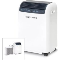
USER MANUAL PAC 4600 TROTEC
Inhaltsverzeichnis
Read these operating instructions carefully before commissioning / using this device!
These instructions are an integral part of the system and must always be kept near or on the device.
Subject to modifications; No liability accepted for errors or misprints!
Assembly and operating instructions (original)
Table of contents
1 Safety and usage instructions...... B-4
1.1 General safety notes...... B-4
1.2 Identification of notes...... B-4
1.3 Personnel qualifications...... B-4
1.4 Dangers of failure to observe the safety notes...... B-4
1.5 Safety-conscious working...... B-4
1.6 Safety notes for the operator.... B-5
1.7 Safety notes for installation, maintenance and inspection...... B-5
1.8 Unauthorised modification and changes...... B-5
1.9 Intended use...... B-5
1.10 Legal notice...... B-5
1.11 Transport and packaging...... B-6
1.12 Environmental protection and recycling...... B-6
2 Technical data...... B-7
3 Structure and function...... B-8
2.1 Technical data..... B-7
4 Operation...... B-9
5 Installation...... B-11
6 Connecting line B-14
7 Electrical connection B-17
8 Troubleshooting and customer service B-18
9 Care and maintenance B-19
10 Shut-down B-20
11 Exploded view and spare parts lists...... B-21
11.1 Exploded view indoor unit.... B-21
11.2 Spare parts list - Indoor unit...... B-22
11.3 Exploded view outdoor unit...... B-23
11.4 Spare parts list - Outdoor unit...... B-24
12 Index...... B-25
1 Safety and usage instructions
1.1 General safety notes
Carefully read the operating manual before commissioning the units for the first time. It contains useful tips and notes such as hazard warnings to prevent personal injury and material damage. Failure to follow the directions in this manual not only presents a danger to people, the environment and the system itself, but will void any claims for liability.
Keep this operating manual and the refrigerant data sheet near to the units.
1.2 Identification of notes
This section provides an overview of all important safety aspects for proper protection of people and safe and fault-free operation. The instructions and safety notes contained within this manual must be observed in order to prevent accidents, personal injury and material damage.
Notes attached directly to the units must be observed in their entirety and be kept in a fully legible condition.
Safety notes in this manual are indicated by symbols. Safety notes are introduced with signal words which help to highlight the magnitude of the danger in question.

DANGER!
Contact with live parts poses an immediate danger of death due to electric shock. Damage to the insulation or individual components may pose a danger of death.

DANGER!
This combination of symbol and signal word warns of a situation in which there is immediate danger, which if not avoided may be fatal or cause serious injury.

WARNING!
This combination of symbol and signal word warns of a potentially hazardous situation, which if not avoided may be fatal or cause serious injury.

CAUTION!
This combination of symbol and signal word warns of a potentially hazardous situation, which if not avoided may cause injury or material and environmental damage.

NOTICE!
This combination of symbol and signal word warns of a potentially hazardous situation, which if not avoided may cause material and environmental damage.

This symbol highlights useful tips and recommendations as well as information for efficient and fault-free operation.
1.3 Personnel qualifications
Personnel responsible for commissioning, operation, maintenance, inspection and installation must be able to demonstrate that they hold a qualification which proves their ability to undertake the work.
1.4 Dangers of failure to observe the safety notes
Failure to observe the safety notes may pose a risk to people, the environment and the units. Failure to observe the safety notes may void any claims for damages.
In particular, failure to observe the safety notes may pose the following risks:
The failure of important unit functions.
The failure of prescribed methods of maintenance and repair.
- Danger to people on account of electrical and mechanical effects.
1.5 Safety-conscious working
The safety notes contained in this installation and operating manual, the existing national regulations concerning accident prevention as well as any internal company working, operating and safety regulations must be observed.
1.6 Safety notes for the operator
The operational safety of the units and components is only assured providing they are used as intended and in a fully assembled state.
The units and components may only be set up, installed and maintained by qualified personnel.
■ Protective covers (grille) over moving parts must not be removed from units that are in operation.
Do not operate units or components with obvious defects or signs of damage.
- Contact with certain unit parts or components may lead to burns or injury.
The units and components must not be exposed to any mechanical load, extreme levels of humidity or extreme temperature.
Spaces in which refrigerant can leak sufficient to load and vent. Otherwise there is danger of suffocation.
All housing parts and device openings, e.g. air inlets and outlets, must be free from foreign objects, fluids or gases.
The units must be inspected by a service technician at least once annually. Visual inspections and cleaning may be performed by the operator when the units are disconnected from the mains.
The local room air conditioner is designed for flexible use in living and work spaces. Year-round operation is not recommended.
Do not leave the appliance running for an extended period unsupervised.
1.7 Safety notes for installation, maintenance and inspection
■ Appropriate hazard prevention measures must be taken to prevent risks to people when performing installation, repair, maintenance or cleaning work on the units.
The setup, connection and operation of the units and its components must be undertaken in accordance with the usage and operating conditions stipulated in this manual and comply with all applicable regional regulations.
■ Local regulations and laws such as Water Ecology Act must be observed.
The power supply should be adapted to the requirements of the units.
Units may only be mounted at the points provided for this purpose at the factory. The units may only be secured or mounted on stable structures, walls or floors.
■ Mobile units must be set up securely on suitable surfaces and in an upright position. Stationary units must be permanently installed for operation.
The units and components should not be operated in areas where there is a heightened risk of damage. Observe the minimum clearances.
The units and components must be kept at an adequate distance from flammable, explosive, combustible, abrasive and dirty areas or atmospheres.
Safety devices must not be altered or bypassed.
1.8 Unauthorised modification and changes
Modifications or changes to units and components are not permitted and may cause malfunctions. Safety devices may not be modified or bypassed. Original replacement parts and accessories authorised by the manufactured ensure safety. The use of other parts may invalidate liability for resulting consequences.
1.9 Intended use
Depending on the model, the equipment and the additional fittings with which it is equipped is only intended to be used as an air-conditioner for the purpose of cooling or heating the air in an enclosed room..
Different or additional use shall not be classed as intended use. The manufacturer/supplier assumes no liability for damages arising from an unintended use of the equipment. The user bears the sole risk in such cases.
Using the equipment as intended also includes working in accordance with the operating manual and installation instructions and complying with the maintenance requirements.
Under no circumstances should the threshold values specified in the technical data be exceeded.
1.10 Legal notice
This publication replaces all previous ones. No part of this publication may be reproduced in any form without our written permission or processed using electronic systems, duplicated or distributed. Subject to technical changes. All rights reserved. Brand names are used without guarantee of free usability following and essentially as the manufacturer describes. The product names used are registered and should be treated as such. Scope of delivery may differ from the product. This document has been prepared with due care. We assume no liability for errors or omissions.
© TROTEC®
PAC 4600
1.11 Transport and packaging
The devices are supplied in a sturdy shipping container. Please check the equipment immediately upon delivery and note any damage or missing parts on the delivery and inform the shipper and your contractual partner. For later complaints can not be guaranteed.

WARNING!
Plastic films and bags etc. are dangerous toys for children!
Why:
- Leave packaging material are not around.
- Packaging material may not be accessible to children!
1.12 Environmental protection and recycling
Disposal of packaging
All products are packed for transport in environmentally friendly materials. Make a valuable contribution to reducing waste and sustaining raw materials. Only dispose of packaging at approved collection points.

Disposal of equipment and components
Only recyclable materials are used in the manufacture of the devices and components. Help protect the environment by ensuring that the devices or components (for example batteries) are not disposed in household waste, but only in accordance with local regulations and in an environmentally safe manner, e.g. using certified firms and recycling specialists or at collection points.

2 Technical data
2.1 Technical data
Unit data
| Series PAC 4600 | | | PAC 4600 S-LINE |
| Operating mode Local inverter room air conditioner in split design |
| Nominal cooling output1) | kW 4.30 (1.80 to 4.60) |
| Energy efficiency ratio,1) | | B |
| Energy efficiency size SEER1) | | 4.6 |
| Power consumption, annual, QCE | kWh 346 |
| Application area (room volume), approx. m3 120 |
| Adjustment range indoor unit °C/%r.H. +16 to +30 / 35 to 80 |
| Operating range outdoor unit °C/%r.H. +21 to +43 / 35 to 80 |
| Refrigerant | | R 410A3) |
| Max. operating pressure kPa 4200 | | |
| Air volume flow per level, indoor unit m3/h 380 / 520 / 600 |
| Max. airflow volume outdoor unit m3/h 1000 |
| Sound pressure level p. stage, ind. unit2) | dB(A) 45 / 48 / 54 |
| Sound power level max., IT/AT dB(A) | | 59 / 64 |
| Power supply | V/Hz | 230 / 1~/ 50 |
| Enclosure class indoor unit / outdoor unit | IP | 24 / X4 |
| Electr. rated power consumption1) | kW | 1.31 |
| Electr. rated current consumption1) | A | 5.60 |
| Elec. starting current max., LRA | A | 8.00 |
| Condensate pump, flow rate, max. | mm WS | 1800 |
| Refrigerant, basic capacity | kg | 1.08 |
| Refrigerant piping, length | mm | 3000, 2300 usable |
| Dimensions indoor unit H/W/D | mm | 695 / 470 / 335 |
| Dimensions outdoor unit H/W/D | mm | 490 / 510 / 230 |
| Weight indoor unit kg | 35.0 |
| Weight outdoor unit | kg | 14.0 |
| Standard colour | | white silver | |
| Serial number | | 1288... | 1289... |
| EDP no. | | 1615490 | 1615491 |
1) Air inlet temperature TK 27°C / FK 19°C, outside temperature TK 35 °C, FK 24 °C, max. air flow volume
2) Distance 1m free field
3) Contains greenhouse gas per Kyoto protocol (see also information in "Connecting line" chapter)
3 Structure and function
Equipment description
The device is particularly suited for flexible operation, but can also be mounted in a stationary installation. The local air conditioning unit is comprised of an indoor unit for setting up on the floor indoors and an outdoor unit for wall or ground installation outdoors. In "cooling" mode, the output produced by the compressor precisely matches itself to requirements, and thereby regulates the nominal temperature with minimal temperature deviations. This "inverter-technology" results in energy savings over conventional split systems and also reduces noise emissions to a particularly low level. The flexible connection pipe serves to transport the heat outdoors. The outdoor unit discharges the absorbed heat to the outdoor air by means of a heat exchanger (condenser). The condensate collected during cooling operation is transported to the outdoor unit by means of a condensate pump integrated into the indoor unit and evaporates via the heat exchanger. The device filters and dehumidifies the air and thereby creates a comfortable room climate. It works fully automatically and offers numerous additional options thanks to its microprocessor control system. The device can be conveniently operated by means of the infrared remote control unit included.
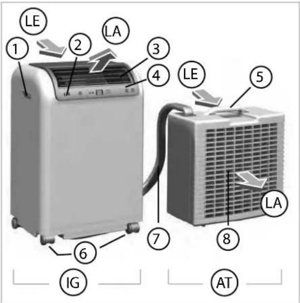
Fig. 1: Front view
IG Indoor unit
AT Outdoor unit
LA Air outlet
LE Air intake
1 Recessed grip
2 Infrared receiver
3 Ventilation louvers
4 Control panel
5 Carrying handle
6 Conveyor rollers
7 Connector pipes
8 Condenser fan (back side)
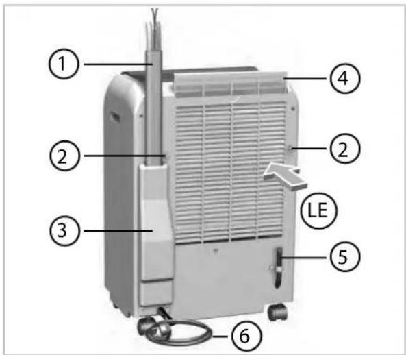
Fig. 2: Rear view (indoor unit)
LE Air intake
1 Connector pipes
2 Mount for the outdoor unit
3 Cover
4 Air filter
5 Condensate drain
6 Mains lead with plug
4 Operation
The system can be operated by means of the control panel on the device or via the standard infrared remote control unit. The functional operation of the buttons among themselves is identical, however, the designation can vary. The batteries must be correctly inserted before the infrared remote control is used.

Fig. 3: Control panel
Legend
① „ON / OFF“ button
② „MODE“ button (Fan speed-mode)
The fan speed is indicated by means of LEDs in the selected modes AUTO-HI-MED-LO or circulated air mode FAN.
Indication of the automatic fan operation.
④ LED „HI“ (Fan mode)
Indication of the high fan operation.
⑤ LED „MED“ (Fan mode)
Indication of the average fan operation.
⑥ LED „LO“ (Fan mode)
Indication of the low fan operation.
⑦ LED „DE- HUM.“ (Dehumidifying mode)
Indication of the dehumidifying mode.
⑧ LED „FAN“ (Circulated air)
Indication of the circulated air.
⑨ LED „COMP. ON“ (Compressor operation)
The controller controls the cooling output by means of switching the compressor on or off. Compressor operation is indicated by means of the LED. If the LED flashes, the compressor will be activated in max. 3 mins.
⑩ Button „▼ ▲“ Temperature setting
The desired nominal temperature can be set with the „▼▲“ buttons in steps of 1°C between 16 and 30°C.
⑪ Display
The display shows the set nominal temperature or the residual time of a programmed timer.
⑫ "ON" and "OFF" timer
The timer function can be used to switch the device on or off automatically in hourly intervals („▼▲“ buttons) by means of pressing the "SET" button. The function can be used to program the switch-on timer when the device is off and the switch-off timer when the device is on, for up to 24 hours. Both timers can be deleted by means of pressing the "RESET" button.
Indicator of activation (LED ON) or deactivation (LED OFF) of the timing on and off
⑭ „AUTO SWING“ button
The direction of the discharged air via the oscillating fins can be adjusted to fixed or oscillating by pressing the "AUTO SWING" button.
⑮ LED „DRAIN WATER“
If the pump is unable to transport the collected condensate then this is signalised via an acoustic alarm in combination with the flashing "DRAIN WATER" LED. The device will be operational again after the container is emptied by means of the condensate drain.
⑯ Infrared receiver
The device receives the signals from the infrared remote control via the sensor.
⑰ „FAN“ button(only on the infrared remote control)
The ventilator speed can be adjusted by means of pressing the "FAN" button.
PAC 4600
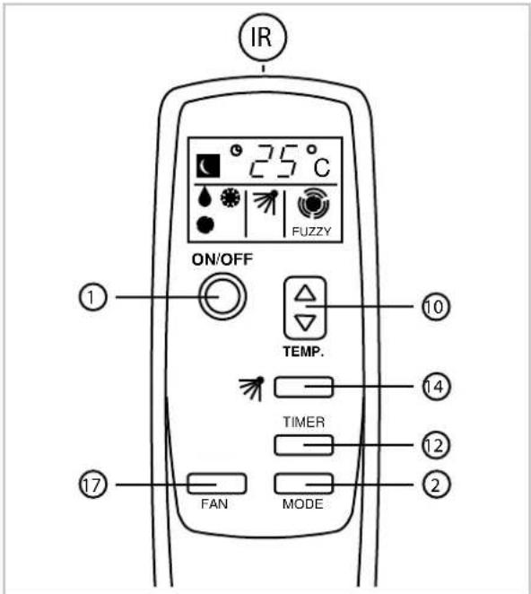
Fig. 4: Infrared remote control
IR Infrared transmitter
Cooling mode (※)
- Switch the unit on by means of the "I / 0" button.
- Set the temperature selection switch to the desired nominal temperature.
- Select the desired fan mode to AUTO, HI, MED or LO by means of the "MODE" button.
Circulated air mode (
- Switch the unit on by means of the "I / 0" button.
- Select FAN mode by means of the "MODE" button. (Remote control
The outdoor unit can remain in the room in circulated air mode. However, do not hang the outdoor unit onto the indoor unit.
Indication of the fan speed:
= high speed
● = average speed
● = low speed
= automatic speed
Dehumidifying mode DE-HUM. (▲)
Position the indoor unit and the outdoor unit in the room that is to be dehumidified.
- Ensure that the indoor unit cannot extract warm air from the outdoor unit.
- Do not hang the outdoor unit onto the indoor unit.
- Please observe: The condensate formed during dehumidification may not be pumped to the outdoor unit as otherwise it will be dissipated back into the air in the room or may run out of the outdoor unit.
- Take the condensate drain hose on the back of the indoor unit out of its bracket and remove the plug.
- Allow the condensate to drain downwards into a drain or container.
! NOTICE!
Ensure that the external container does not overflow. This could result in water damage.
- Switch the unit on by means of the "I / 0" button.
- Set the temperature selection switch to the lowest nominal temperature.
- Set the "MODE" button to the lowest fan speed "LO".
5 Installation
Installation instructions
The device is supplied in a fully operational condition and is equipped as standard with a 3.0 m long connection pipe linking the indoor and outdoor devices, meaning that it is ready for use. The scope of delivery includes various accessories for mounting the outdoor unit.
Indoor unit
The indoor unit is positioned at the desired location with the air discharge side pointing into the room. When positioning, ensure there is a minimum gap of 20 cm around the device.
Connector pipes
The connector pipes can be laid through a tilted window or through a gap in the door. The connector pipe can be separated from the indoor unit, meaning that there is the additional option of fitting it to a wall opening ( min. 60 mm). Please note the following information when laying the connector pipes:
The connector pipes may not be jammed in or kinked.
There may not be any tension of other mechanical stress exerted on the connector pipes.
The pipe insulation and the protective jacket may not be damaged.
Outdoor unit
The outdoor unit expels the heat from the room into the outside air. In order to do so, the outdoor unit can be positioned on the ground or mounted on an external wall.
Installation on the ground
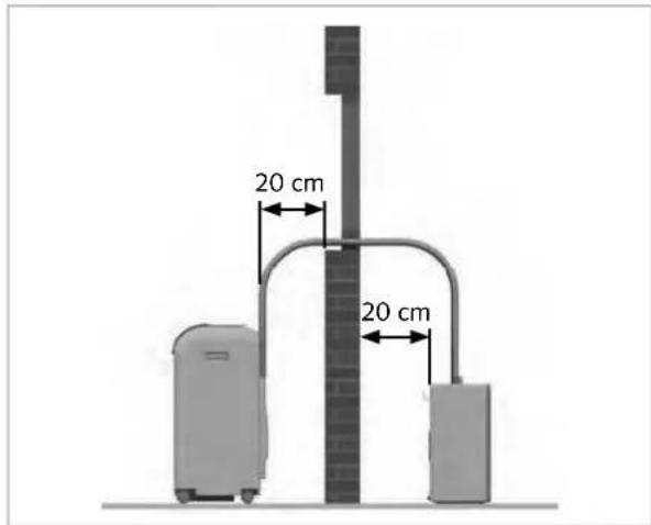
Fig. 5: Minimum clearance to wall
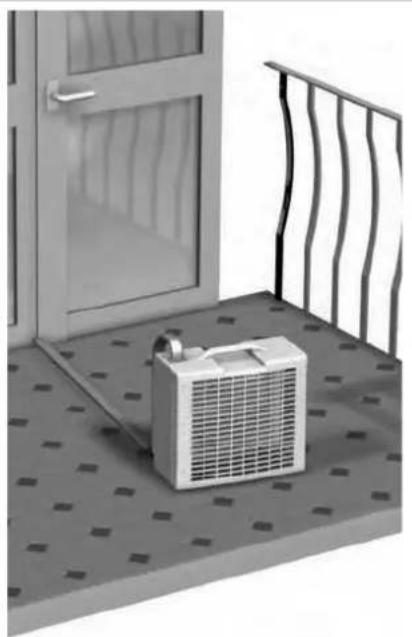
It is not necessary to use any mounting accessories when installing the outdoor unit on a patio or balcony. The outdoor unit should be positioned vertically and protected from direct sunlight. A minimum gap of 20 cm should be maintained from the air discharge side to the wall. It must be ensured that the air can be discharged freely (min. 50 cm gap to any obstacles). The connecting pipe is fed through a gap in the window (Fig. 5) or door (Fig. 7).
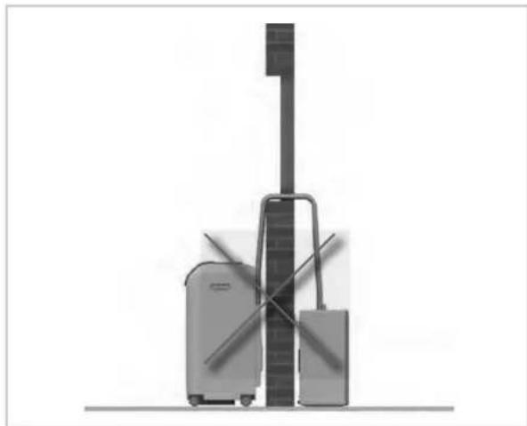
Fig. 6: Absence of minimum gap
PAC 4600
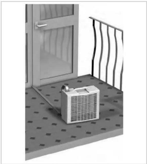
Fig. 7: Example assembly outdoor unit
Mounting on an external wall with wall bracket
- Fasten to the wall using the supplied wall bracket.
Hook the outdoor unit into the wall bracket and secure it with the supplied M4 bolts (Fig. 8 and Fig. 9).
The wall brackets can be fastened with the supplied fastening elements (dowel 6mm and screws).
Should this not be suitable for the characteristics of the wall then the fastening elements should be selected on site to ensure suitable holding force. When mounting, ensure that the cable is not stressed and that the insulation is not damaged in the process. Maintain the minimum gaps. The air outlets of the indoor and outdoor units may not be blocked.
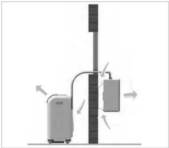
Fig. 8: Required air circulation
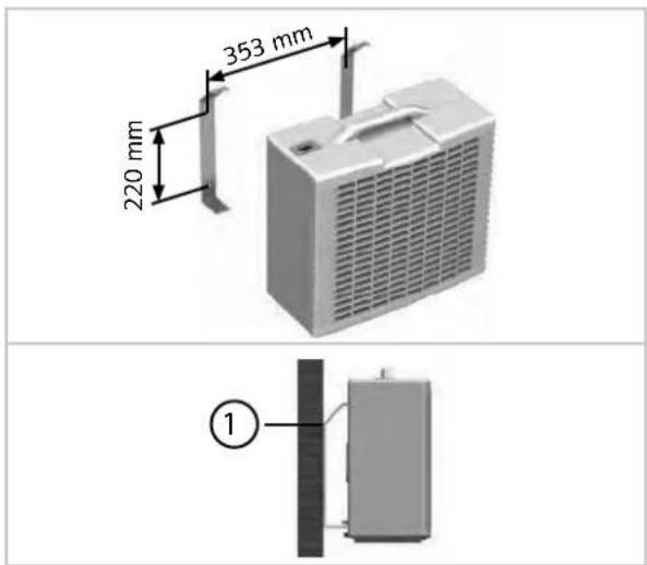
Fig. 9: Gaps assembly bracket
1 Safety bolt M4
Mounting height
The outdoor unit (lower edge) may only be mounted max. 1.8 m above the installation level of the indoor unit (Fig. 10). If the outdoor unit is mounted below the installation level of the indoor unit, then the height difference may not exceed 1.5 m.
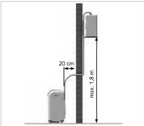
Fig. 10: Max. assembly height
External wall mounting with fastening straps
Fastening straps are an additional option for mounting the outdoor unit to an external wall or parapet wall.
Hook the wall bracket onto the outdoor unit and secure it with the screws (M4).
Hook one end of the fastening strap with the spring catch into the fastening eyelet of the outdoor unit.
Hook the other end of the fastening strap into the eyelet bolt which is to be attached to the on-site external wall or parapet wall (Fig. 11). Ensure sufficient stability.

NOTICE!
Depending on weather conditions it is possible that condensate will run out of the condensate drain on the rear of the outdoor unit. This is a normal process. Select the installation site for the outdoor unit in such a way as the draining water cannot cause any form of damage or hook up the connection to a drain.
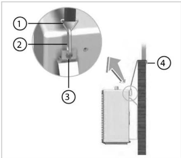
Fig. 11: Assembly with fastening straps
1 Spring catch
2 Fastening eyelet
3 Safety bolt M4
4 Eyebolt
PAC 4600
6 Connecting line
The connecting line is connected to the indoor unit with quick-release couplings. This provides the facility to disconnect the connecting line from the indoor unit for assembly purposes without losing refrigerant.

DANGER!
The unit must be disconnected from the mains supply during the entire process! It may only be switched back on when all of the connections have been made and checked. The fastenings and all of the covers must be attached beforehand.

DANGER!
Suitable protective gear must be worn when connecting or disconnecting the connection pipe.

NOTICE!
The escape of refrigerant contributes to climatic change. In the event of escape, refrigerant with a low greenhouse potential has a lesser impact on global warming than those with a high greenhouse potential. This device contains refrigerant with a greenhouse potential of 1975. That means the escape of 1 kg of this refrigerant has an effect on global warming that is 1975 times greater than 1 kg CO 2 , based on 100 years. Do not conduct any work on the refrigerant circuit or dismantle the device - always enlist the help of qualified experts.
Instructions for disconnecting the connecting line:
- Disconnect the units only immediately before assembly and only leave the units disconnected for as long as is absolutely necessary.
Before the pipes are reconnected, it is to be ensured that there is no dirt, moisture or other foreign bodies in the quick release couplings which could impair their function.
■ Always mount the cable strap as soon as the pipelines are connected.
The pipelines may only be disconnected and connected by authorised specialist engineers.
The unit can be disconnected and reconnected approx. 7 times without experiencing a noticeable loss of cooling capacity, assuming the work is carried out properly.
In doing so, the following procedure must be adhered to:
- Switch the unit off.
- Pull the power plug out of the socket.
- Remove the 2 screws from the cover on the rear side of the unit (Fig. 12).
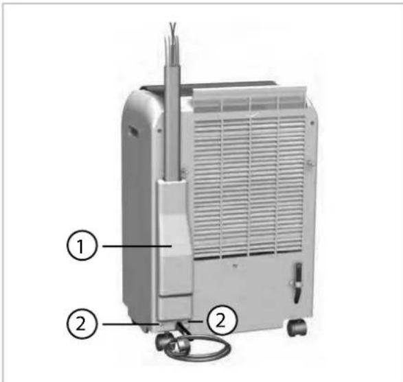
Fig. 12: Rear view, indoor unit
1: Cover
2: Screws
-
Remove the cover from the unit.
-
Unscrew the cable strap from the connecting line (Fig. 13).
-
Push in the side clips on the plugged connection and pull the plug out of the socket (Fig. 13).
-
Remove the upper section from the bracket by means of unscrewing the two screws (Fig. 13).
-
Pull off the condensate drainage hose (Fig. 13).
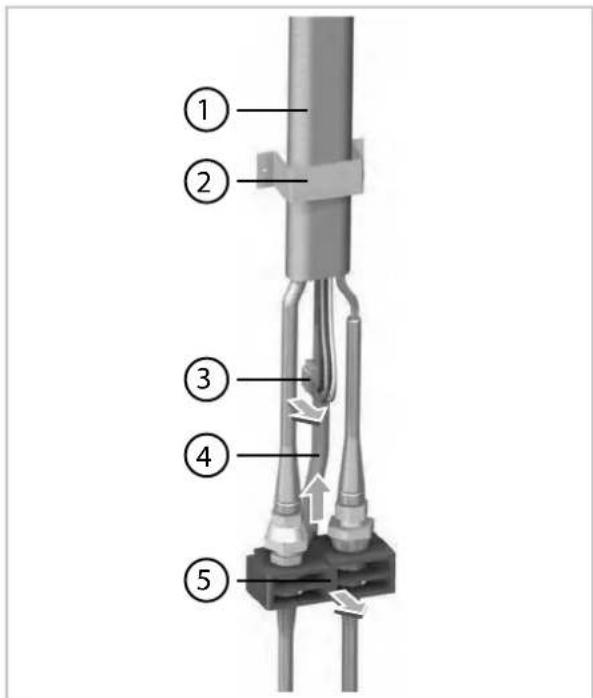
Fig. 13: Dismantling the connecting line
1: Connecting line
2: Cable strap
3: Plug connection
4: Condensate hose
5: Cable strap
- Unscrew the left-hand union nut with the size 24 open-ended spanner provided. In doing so, use the second size 21 open-ended spanner to hold the lower coupling section still (Fig. 14).

NOTICE!
Never twist the the fixed lower section.

NOTICE!
It is possible that residual fluid can leak out of the condensate hose.
- Screw continuously until the connection is disconnected.

NOTICE!
Do not stop screwing in the event that refrigerant escapes and a slight hissing sound is heard.
PAC 4600
- Unscrew the right-hand union nut with the size 24 open-ended spanner provided. In doing so, use the second size 21 open-ended spanner to hold the upper coupling section still (Fig. 15).

NOTICE!
Never twist the the fixed upper section.
- Screw continuously until the connection is disconnected.

NOTICE!
Do not stop screwing in the event that refrigerant escapes and a slight hissing sound is heard.
- Screw the protective caps provided onto the 4 coupling halves (Fig. 16).
- Ensure that there is a wall opening available of ∅ 60 mm in the event that the connecting line is to be fed through a wall.
- After the placement or mounting of the indoor unit and outdoor unit is complete, the connecting line can be hooked up to the indoor unit in the opposite order.
- After making the connections, check the quick-release couplings for leaks.
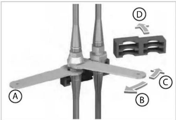
Fig. 14: Unscrew the left-hand union nut
A: Hold to prevent turning
B: Tighten
C: Loosen
D: Remove cable strap
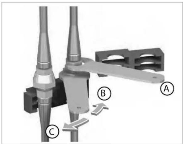
Fig. 15: Unscrew the right-hand union nut
A: Hold to prevent turning
B: Tighten
C: Loosen
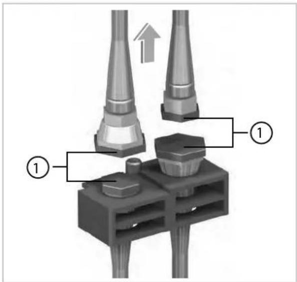
Fig. 16: Screw on protective caps
1: Protective caps
7 Electrical connection
Electrical connection diagram
![graph TD subgraph PCB1 A["PCB1"] --> B["PCB2"] B --> C["SM"] C --> D["PCB4"] D --> E["PCB5"] E --> F["FM2"] end subgraph PCB2 G["PCB2"] --> H["SM"] H --> I["PCB4"] I --> J["PCB5"] end subgraph PCB3 K["PCB3"] --> L["FM2"] end subgraph PCB4 M["PCB4"] --> N["SM"] N --> O["PCB5"] end subgraph PCB5 P["PC…](/content/2026/02/377773/images/1c9ad5d8493ebd3e4c23956abcaab3efd2f0345302c01e8c52a4d1ecfb7007a4.jpg)
Fig. 17: Electrical connection diagram
PCB1 Control board
PCB2 Main board
SM Swing motor
FM1 Vaporiser fan
FM2 Condenser fan
WM Condensate pump
CM Compressor
OLP Compressor excessive temperature protection
RT Sensor circulating air temperature
CT Sensor frost protection
MS1 Microswitch alarm (container full)
MS2 Microswitch condensate pump
Colour code:
BK Black
BR Brown
BU Blue
GR Gray
OR Orange
R Red
W White
Y Yellow
8 Troubleshooting and customer service
The unit has been manufactured using state-of-the-art production methods and tested several times to ensure its correct function. If malfunctions should occur, please check the unit as detailed in the list below. If all functional checks have been carried out and the device still fails to operate properly, then please notify your nearest specialist dealer.
Functional trouble
| Fault description Cause Remedy | | |
| The unit does not start Mains failure | Check voltage and if necessary | waituntil power is back on |
| Mains fuse or controller fuse faulty | Arrange to have exchanged |
| Mains plug not inserted in socket | Insert mains plug |
| Condensate container full, display "DRAIN WATER" flashes | Empty container via condensate drain hose |
| Timer mode active Wait for timer | period to expire or press"I / 0" button again |
| The unit is running with Reduced ventilation output | Used air or outlet openings soiled or blocked by foreign bodies | Clean the openings Remove foreign bodies |
| Filter soiled Clean the filter in accordance with the instructions |
| Outdoor unit soiled Clean the fins on the inside of the outdoor unit |
| Cooling load of the room excessive | Reduce the thermal load |
| Condensate leaks out of the unit Device standing at an angle Position | vertically, ensure stable positioning |
| Plugs missing from condensate drain hose | Seal the hose so that it is watertight again |
Error codes
| Error codes Fault description / note |
| 01 I/O PCBA error communication |
| 02 Air intake sensor defective |
| 03 Evaporator sensor defective |
| 32 Liquid line sensor defective |
| 33 Hot gas sensor compressor defective |
| 35 Compressor speed is not correct |
| 36 Compressor over temperature |
| 37 Liquid line heat exchanger is too high |
Error codes Fault description / note
38 Low power AC
39 High power AC(A)
40 AC(PCON) overcurrent active
41 IPM board error communication
42 IPM board general error
43 IPM board DC overcurrent
44 PFC overcurrent
45 Over-/undervoltage
46 IPM board current error
47 PFC over temperature
9 Care and maintenance
Regular care and observation of some basic points will ensure trouble-free operation and a long service life of the unit.
The device should be checked and thoroughly cleaned after each prolonged use, but in any case at least once per year.
The entire plant is designed as a maintenance free, hermetically sealed system and may only be maintained or repaired by specialist authorised firms.

DANGER!
Prior to performing any work, ensure the equipment is disconnected from the voltage supply and secured to prevent accidental switch-on!
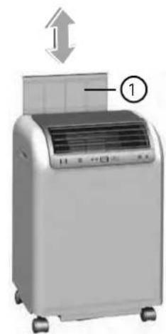
Fig. 18: Remove filter
1 Filter
- Clean the equipment using a damp cloth. Do not use a jet of water.
Do not use any caustic, abrasive or solvent-based cleaning products.
Only use suitable cleaning agents, even in the event of severe soiling.
■ Empty the condensate container and check if the diameter of the condensate lines have tapered as a result of soiling prior to and after each operating season. If this is the case, they must be cleaned.

NOTICE!
Check the level of dirt on the on the exchanger fins.
- Clean the air filter on the indoor unit at regular intervals, and more frequently if necessary.
PAC 4600
It is recommended that you take out a maintenance contract with an appropriate specialist firm.

This enables you to ensure the operational reliability of the plant at all times!

NOTICE!
Never operate the indoor unit without the original filter. The heat exchanger fins on the indoor unit with soil up if operated without a filter and the device will suffer performance loss.
Air filter for indoor unit
Clean the air filter at intervals of no more than 2 weeks. Reduce this interval if the air is especially dirty.
Cleaning the filter on the indoor unit
Please proceed as follows in order to clean the unit:
- Remove the mains plug.
- Pull the filter out of the unit (Fig. 18).
- Clean the filter of dust. Use a vacuum cleaner in the event of slight soiling.
- In the event of more severe soiling, carefully clean in lukewarm water.
- Subsequently allow the filter to dry in the air.
- Insert the filter back into the device.
10 Shut-down
! NOTICE!
Never switch off the equipment by pulling out the mains plug.
Temporary shut-down
If it is planned to shut down the equipment for longer periods e.g. during the winter, proceed as follows:
- Allow the equipment run for 2-3 hours in circulation mode. This extracts any residual humidity from the unit.
- Shut down the equipment by pressing the "I / 0" button on the operating panel. Only then should you pull out the mains plug and wind up the cable.
- Empty the internal condensate container via the condensate drain hose on the rear side of the indoor unit.
- Make sure that there is no condensate in the outdoor unit before storing the indoor and outdoor unit indoors. To drain the condensate, remove the plug from the outdoor unit.
- Clean the filter and the plastic surfaces.
- Hang the outdoor unit onto the indoor unit.
- Cover the equipment with a synthetic tar-paulin to protect it against dust.
- Store the equipment in a cool and dry location away from direct sunlight.
11 Exploded view and spare parts lists
11.1 Exploded view indoor unit
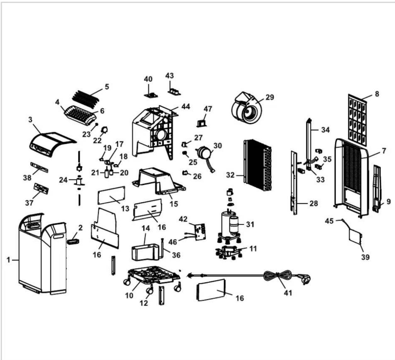
Fig. 19: Exploded view indoor unit
We reserve the right to modify the dimensions and design as part of the ongoing technical development process.
11.2 Spare parts list - Indoor unit
Please contact TROTEC GmbH & Co. KG directly to order spare parts.

IMPORTANT!
To ensure the correct delivery of spare parts, please always the device type with the corresponding serial number (see type plate)
| No. Designation PAC 4600 | | PAC 4600 S-LINE |
| 1 Front panel | |
| 2 Recessed grip |
| 3 Cover, top |
| 4 Exhaust grille |
| 5 Fins |
| 6 Shift lever for fins |
| 7 Back wall |
| 8 Air filter |
| 9 Cover for connecting line |
| 10 Unit base |
| 11 Base plate, cpl. |
| 12 Conveyor rollers |
| 13 Side cover, right / left |
| 14 Condensate container |
| 15 Partition wall | On request by providing the serial number |
| 16 Sound absorption plate |
| 17 Bracket for microswitch |
| 18 Microswitch, (container full) |
| 19 Microswitch, (pump on / off) |
| 20 Float, (container full) |
| 21 Float, (pump on / off) |
| 22 Swing motor for fins |
| 23 Coupling for swing motor |
| 24 Condensation pump cpl. |
| 25 Electrical terminal block |
| 26 Capacitor, evaporator fan |
| 27 Capacitor, condenser fan |
| 28 Frame, rear right |
| 29 Fan, cpl. |
| 30 Evaporator fan | |
| 31 Compressor, cpl. |
| 32 Evaporator |
| 33 Coupling, set (1x m / 1x w) |
| 34 Connecting line, cpl. |
| 35 Fastening block, cpl. |
| 36 Condensate drain hose |
| 37 Keypad board |
| 38 Keypad foil | On request by providing the serial number |
| 39 Control board |
| 40 IPM protection board |
| 41 Mains cable with plug |
| 42 Motherboard |
| 43 Capacitor board |
| 44 Covering for fan |
| 45 Ambient air probe |
| 46 Anti-freeze protection probe |
When ordering spare parts, please quote the serial no., unit number and type (see name plate)!
11.3 Exploded view outdoor unit
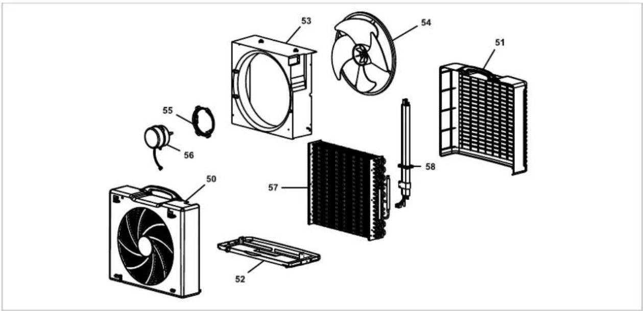
Fig. 20: Exploded view outdoor unit
We reserve the right to modify the dimensions and design as part of the ongoing technical development process.
11.4 Spare parts list - Outdoor unit
| No. | Designation PAC 4600 | | PAC 4600 S-LINE |
| 50 | Back wall | |
| 51 | Front panel |
| 52 | Unit base |
| 53 | Covering for fan | On request by providing the serial number |
| 54 | Condenser fan |
| 55 | Fastening for condenser fan |
| 56 | Condenser fan, motor |
| 57 | Condenser |
| 58 | Seal |
| Spare parts not illustrated |
| Remote control | On request by providing the serial number |
| Capacitor, compressor |
| Fastening set for outdoor unit, cpl. |
| Wall bracket |
When ordering spare parts, please quote the serial no., unit number and type (see name plate)!
12 Index
A
Assembly
Connecting line...... B-14
C
Care and maintenance B-19
D
Disposal of equipment...... B-6
E
Environmental protection...... B-6
Exploded view drawing
Indoor unit...... B-21
Outdoor unit...... B-23
F
Filter cleaning...... B-20
|
Installation
Connector pipes B-11
External wall mounting with fastening
straps B-13
Indoor unit...... B-11
Installation on the ground ...... B-11
Mounting height B-12
Mounting on an external wall with wall
bracket B-12
Outdoor unit...... B-11
M
Maintenance...... B-19
0
Operation
Circulated air mode...... B-10
Control panel...... B-9
Cooling mode B-10
Dehumidifying mode B-10
s
Safety
Dangers of failure to observe the safety
notes...... B-4
General...... B-4
Identification of notes...... B-4
Notes for inspection...... B-5
Notes for installation...... B-5
Notes for maintenance...... B-5
Personnel qualifications...... B-4
Safety-conscious working...... B-4
Safety notes for the operator...... B-5
Unauthorised modification B-5
Unauthorised replacement part manufacture.. B-5
FR
CE
1.3 Qualifications du personnel
Fig. 6: Distance minimale manquante
PAC 4600
Afb. 16: Beschermkappen opschroeven
1: Beschermkappen