
GZPA 1.4000D - Car radio Ground Zero - Free user manual and instructions
Find the device manual for free GZPA 1.4000D Ground Zero in PDF.

| Product Type | Class D Mono Amplifier |
| Brand | Ground Zero |
| Model | GZPA 1.4000D |
| Dimensions (W x H x D) | 53 x 7 x 28.6 cm |
| Weight | 4.5 kg (estimated) |
| Power Supply | 10 - 16 V DC |
| Max Power (4 Ω @ ≤1% THD+N) | 1 x 1000 W |
| Max Power (2 Ω @ ≤1% THD+N) | 1 x 1850 W |
| Max Power (1 Ω @ ≤1% THD+N) | 1 x 2700 W |
| Max Power (1 Ω @ ≤10% THD+N) | 1 x 3500 W |
| Efficiency | > 89% |
| Minimum Impedance | 1 Ω (single), 2 Ω in link mode |
| Low Pass Filter | 50 - 150 Hz, 24 dB/oct |
| Subsonic Filter | 15 - 40 Hz, 24 dB/oct |
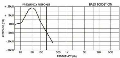
| Bass Boost | 0 - 12 dB (45 Hz) |
| Phase Shift | 0 - 180° |
| Input Sensitivity | 200 mV - 10 V |
| Signal-to-Noise Ratio | > 80 dB |
| Harmonic Distortion (THD) | < 0.04% |
| Frequency Response | 10 - 150 Hz |
| RCA Inputs/Outputs | 1 input, 1 output |
| Bass Remote Control | Yes (Remote Level Control) |
| Link Mode (Master/Slave) | Yes |
| Safety | Overheat and short circuit protection (LED Protect) |
| Chassis Material | Aluminum |
| Warranty | In accordance with legal rights |
| Manufacturer Contact | GROUND ZERO GmbH, Erlenweg 25, D-85658 Egmating, Germany |
Frequently Asked Questions - GZPA 1.4000D Ground Zero
User questions about GZPA 1.4000D Ground Zero
0 question about this device. Answer the ones you know or ask your own.
Ask a new question about this device
Download the instructions for your Car radio in PDF format for free! Find your manual GZPA 1.4000D - Ground Zero and take your electronic device back in hand. On this page are published all the documents necessary for the use of your device. GZPA 1.4000D by Ground Zero.
USER MANUAL GZPA 1.4000D Ground Zero
Limited warranty - defective products must be returned in original packaging - please add a copy of the original purchasing invoice showing the purchasing date and a detailed description of the failure. Failure caused by overload, misuse or by using the product for competition purpose are not covered by the warranty.
www.ground-zero-audio.com
We reserve the right to make needed change or improvement to the product without informing customer about this in advance.

GROUND ZERO
MOBILE ENTERTAINMENT
Amplifier
Owner's Manual
PLUTONIUM
GZPA 1.4000D
Linkable Class D Mono Amplifier

GROUND ZERO
Mobile Entertainment
PLEASE READ BEFORE INSTALLATION
Thank you for selecting a GROUND ZERO Plutonium amplifier.
We are providing a helpful hints list which should keep you from experiencing unnecessary shut down.
FEATURES:
• Class-D High Power Mono Amp
• Efficiency >89%
• Damping Factor >1000 at 100 Hz 4Ω
• 16 Volt max. Power supply
- Unkable
• 1 Ω stabil (Unkmode 2Ω stabil)
• Full Power MOS-FET Amplifier
• Power und Protect LED
• Lowpass 50 - 150Hz with 24dB/Oct
• Subsonicfilter 15 - 40Hz with 24dB/Oct
• Aluminium heat sink
• Input Sensitivity 200 mV - 10 Volt
• RCA 1 x Input/ 1 x Output
• Bassremote Control
• Bassboard 0 - 1.2 dB (45 Hz)
Phase Shift: 0 - 180°
TOOLS AND MATERIALS YOU NEED:
• SCREWDRIVER; ELECTRIC DRILL; 1/8 CARBIDE DRILL BIT;
• USE 2AWG POWER WIRE (min. 35 mm ^4 )
• GROUND YOUR AMPLIFIER ONE METER CLOSE TO INSTALLATION LOCATION
• USE 12 AWG SPEAKER WIRE OR HEAVIER FROM YOUR AMPLIFIER TO YOUR SPEAKERS
• LOOK FOR BURS IN THE PATH OF YOUR WIRES AND FILE THEM FLAT TO AVOID PUNCTURE
• USE 16 AWG WIRE FOR REMOTE TRIGGER
NOTE ALL WIRE GAUGES ARE BASED ON STRANDED WIRE WITH POLARITY INDICATORS ON TWO WIRE CONFIGURATIONS
PLEASE USE GREAT CAUTION DRILLING YOUR TRUNK, YOUR GAS TANK AND BRAKE LINES CAN BE DAMAGED BY PUNCTURING WITH YOUR DRILL BIT: THIS COULD CAUSE DAMAGE OR FAILURE OF YOUR CARS OPERATING SYSTEMS:
INTRODUCTION
Amplifiers provide high-performance sound reinforcement for you mobile audio equipment. It's versatility enables compatibility with optional equalizer, frequency dividing network crossovers, and other audio processors in a customized system.
The Multi-Mode bridging capabilities allow flexibility in hosting several different speaker configurations.
To achieve optimum performance, it is highly recommend that you read this owners manual before beginning the installation
WARNING
High powered audio systems in a vehicle are capable of generating "Live Concert" high level of sound pressure. Continued exposure to excessively high volume sound levels may cause hearing loss or damage. Also, operation of a motor vehicle while listening to audio equipment at high volume levels may impair your ability to hear external sound such as: horns, warning signals, or emergency vehicles, thus constituting to a potential traffic hazard. For safety reasons we recommends listening at lower volume levels while driving.
MOUNTING YOUR AMPLIFIER:
The mounting position of your amplifier will have a great effect on its ability to dissipate the heat generated during normal operation. It has an ample heat sink for heat dissipation, and is also designed with a thermal shut-down(for heat protection) circuit, DO NOT enclose the amplifier in a small box or cover it.
Temperatures in car trunks have been measured as high as 175°F(60 Celsius) in the summer time, since the thermal shut-down point for the amplifier is 185°F(85 Celsius) it is easy to see that it must be mounted for maximum cooling capability. To achieve maximum advantage of convection air flow in a enclosed trunk, mount the amplifier in a vertical position, on a vertical surface.
Floor mounting under the seat is usually satisfactory as long as there is at least 1 inch (2 cm) above the amplifier's fins for ventilation.
a) selected a suitable location that is convenient for mounting, is accessible for wiring and has enough room for air circulation and cooling.
b) Use the amplifier as a template to mark the mounting holes, remove the amplifier and drill 4 hols, use extreme caution, inspect underneath surface before drilling.
c) Secure the amplifier by using screws.
CAUTION:
AS A PRECAUTION; IT IS ADVISABLE TO DISCONNECT THE VEHICLE'S BATTERY BEFORE MAKING CONNECTION TO THE +12 VOLTS SUPPLY WIRUNG (see owner's manual of your car for further in formation!)
min. 35mm ^2 (thicker if planning for additional amplifiers) wire is recommended both the power and grounds. Both types are available at most Mobile audio dealers or Installation shops.
1.) GROUND: To vehicle Chassis
To avoid ignition noise caused by ground loops, it is necessary that the amplifiers be grounded to a clean, bare metal surface of the vehicles chassis.
NOTE: GROUND WIRE SHOULD NOT BE EXTENDED MORE THAN 3 FT.(1 Meter) min. 35mm ^2
2.) +12 Volt (Fused) Constant power: To Battery (+)
Due to the power requirements of the amplifier, this connection should be made directly to the positive (+) terminal of battery. For safety reasons, install an in-line fuse holder (not included) as close to the battery positive
(+) terminal as possible with a rating not exceeding value of fuses in amp.
3.) Remote Turn-On Input: to power antenna output of Car Stereo
This amplifier is turned "ON" remotely when the vehicle's stereo is turned "ON".
NOTE:
IF YOUR RADIO DOES NOT HAVE +12 VOLT OUTPUT LEAD ;THE "REM" TERMINAL ON THE AMPLIFIER CAN BE CONNECTED TO VEHICLE'S ACCESSORY CIRCUIT THAT IS LIVE WHEN THE KEY IS "ON".
(1) Input L/R
(2) Output L/R
(3) Input Slave Master
(4) Power/ Protection LED
(5) Input sensitivity adjustment
(6) Sub sonic filter
(7) Bass boost
(8) Variable low pass filter
(9) Phase shift controls 0-180°
(10) Remote level control
(11) Master Slave switch for linkmode
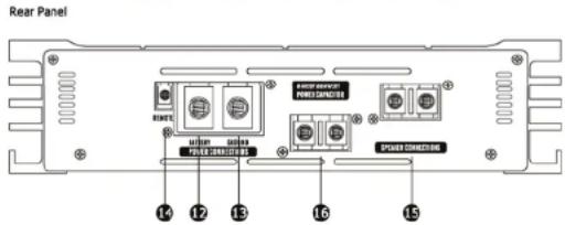
(12) +12 Volt power
(13) Ground terminal GND
(14) Remote +12 Volt
(15) Speaker terminals
(16) Direct power for capacitor
(1) Cinch-INPUT L/R These inputs are for signal cables from the source, always use high quality RCA type shielded cables
(2) Clinch-Output L/R for more amplifiers
(3) Power LED This GREEN LED will illuminate when the amplifier is turned "ON"
(4) Protection LED The amplifier protection circuitry will disable the amplifier if overload, short circuit or extremely high temperature conditions are detected. When the protection mode is in operation, the LED indicator will be illuminated, indicating the amplifier has gone into self-protection mode
(5) Input Sensitivity Adjustment This control adjusts the amplifier's input sensitivity. Input sensitivity is variable from 200mV to 8 Volt. Clockwise increases sensitivity. Counter clockwise decreases sensitivity. This knob is not a volume control for the amplifier. The amplifier can be driven to full power with a wide range of signal levels. A lower signal level will require increased sensitivity for full power. A higher signal level will require decreased sensitivity.
(6) Sub Sonic Filter (15Hz-60Hz)
(7) Bass Boost 0\~+12 dB
(8) Variable Low pass Filter (50Hz-150Hz)
(9) Phase Shift Controls 0-180° Allows the optimum alignment of audio output at speakers for best sonic imaging
(10) Remote Level Control connection for Bass level control
(11) Master-Salve switch for Linkmode
(12) +12 Volt Power Wire the amplifier directly to the car battery
(13) Ground Terminal GND Connect the GND terminal to the chassis ground of your car and take care of the electric and mechanical contact.
(14) Remote+12Volt Wire the remote connections to the auto start lead of your Headunit
(15) Speaker Terminals
(16) Direkt Power for capacitor
ADJUSTMENT AND TUNING
TURNING ON THE AMPLIFIER
The amplifier automatically turns on a few seconds after you turn your vehicle's ignitions switch to ACC. ON or turn on your auto sound system, depending on how you wired the system. The POWER LED on the side of the amplifier lights when the amplifier is on.
Important: Your amplifier requires 30 amps or more of power from your vehicle's battery during operation. To protect your battery from discharging, do not operate the amplifier unless your vehicle is running.
Note: Your amplifier temporarily shuts down if it gets too hot, then restarts automatically once it cools down.
For the best performance, you must set LEVEL (MIN/MAX) on the side of the amplifier to adjust the level of the audio signals.
- Use a screwdriver to turn LEVEL(MIN/MAX) fully to MIN
- Turn the auto sound system's volume control to about two-third of its full range.
- Adjust LEVEL(MIN/MAX) to a comfortable listening level
- Turn up the auto sound system's volume control until the sound begins to distort. Then immediately turn the volume down to a point just before where the distortion began. Caution: Never turn up the auto sound system's volume control more than needed to adjust the audio level, more than two thirds of its maximum volume.
- Adjust LEVEL (MIN/MAX) until the sound is at the maximum level you want the amplifier two produce.
- Adjust the auto sound system's volume control to a comfortable listening level.
line
| FREQUENCY (Hz) | RESPONSE (dB) | | -------------- | ------------- | | 10 | 0 | | 50 | +20 | | 100 | -10 | | 500 | -20 | | 1K | -30 | | 5K | -30 | | 10K | -30 | | 50K | -30 || Model PA 1.4000D | |
| MAX Power4 Ohm @ ≤1% THD+N | 1 x 1000W |
| MAX Power2 Ohm @ ≤1% THD+N | 1 x 1850W |
| MAX Power1 Ohm @ ≤1% THD+N | 1 x 2700W |
| MAX Power2 Ohm @ ≤10% THD+N | 1 x 2000W |
| MAX Power1 Ohm @ ≤10% THD+N | 1 x 3500W |
| Linkable | Yes |
| T.H.D. | <0.04% |
| Signal / Noise Ratio >80dB | |
| Frequency response 10 - 150Hz | |
| Bass Boost 0 - 12dB (45 Hz) | |
| LPF (Low pass Filter) 50 - 150Hz | |
| Subsonic Filter 15 - 40Hz | |
| Damping factor >1000 | |
| Adjustable sensitivity range 200mV - 10V | |
| Operation voltage 10 - 16V | |
| Fuse | No |
| DimensionsW x H x L cm / Inch | 53 x 7 x 28,6 / 20.9" x 2.8" x 11.3" |
Trouble Shooting Guide
| SYMPTOMS CHECK POINTS CURE | ||
| NO SOUND | Is the POWER LED illuminated? Check fuse in amplifier. Make sure remote load is connected check signal leads. Check gain controlCheck Tuncor/Dock volume level | |
| Is the PROTECT LED illuminated? Check for speaker short or amplifier overheating | ||
| AMP NOT SWITCHING ON | No power to the amplifier. Check power wire or connections | |
| No power to remote wire with receiver on | Check connections to radio | |
| Check fuse Replace fuse if broken | ||
| NO SOUND IN ONE CHANNEL | Check speaker leads. Respect for short circuit or an Open connection. | |
| Check audio leads. Reverse left and right RCA inputs to determine i fit is occurring before the amp | ||
| AMP TURING OFF MEDIUM HIGH VOLUME | Check speaker load impedance. Make sure proper speaker load impedance recommendations are observed.(If you use an ohm meter to check speaker resistance, please remember that DC resistance and AC impedance may not be the same) | |
| ON | Temperature shut down Turn radio volume down PROTECTION LAMP | |
| Speaker wires short. Separate speaker wires and isolate | ||
Limited warranty - defective products must be returned in original packaging - please add a copy of the original purchasing invoice showing the purchasing date and a detailed description of the failure. Failure caused by overload, misuse or by using the product for competition purpose are not covered by the warranty.
www.ground-zero-audio.com
We reserve the right to make needed change or improvement to the product without informing customer about this in advance.

GROUND ZERO
Mobile Entertainment
Amplificateur
Mode d'emploi
PLUTONIUM
GZPA 1.4000D
natural_image
Abstract black-and-white striped geometric shape with no text or symbolsGROUND ZERO
Mobile Entertainment
Lire attentivement s.v.p.
(1) Input L/R
(2) Output L/R
(3) Input Slave Master
(4) Power / Protection LED
(5) GAIN
(6) Filtre Subsonic variable
(7) Bass Boost
(8) Filtre passe bas
(9) Phase Shift
(10) Remote Level control
(11) Slave / Master mode
(12) +12 Volt Power branchement
(13) Masse
(14) Remote +12 Volt
(15) Branchement haut parleur
(16) Capacitor
Limited warranty - defective products must be returned in original packaging - please add a copy of the original purchasing invoice showing the purchasing date and a detailed description of the failure. Failure caused by overload, misuse or by using the product for competition purpose are not covered by the warranty.
www.ground-zero-audio.com
We reserve the right to make needed change or Improvement to the product without informing customer about this in advance.


Brand : Ground Zero
Model : GZPA 1.4000D
Category : Car radio