
GZTA 4.24VDC - Car radio Ground Zero - Free user manual and instructions
Find the device manual for free GZTA 4.24VDC Ground Zero in PDF.

| Product type | 4-channel 24V amplifier for commercial vehicles |
| Model | GZTA 4.24VDC |
| Brand | Ground Zero |
| Max power @ 4 Ω (1% THD+N) | 4 x 120 W |
| Max power @ 2 Ω (1% THD+N) | 4 x 200 W |
| Max bridged power @ 4 Ω (1% THD+N) | 2 x 400 W |
| Harmonic distortion (THD) | < 0,04% |
| Signal-to-noise ratio | > 60 dB |
| Frequency response | 10 Hz – 30 kHz |
| High-pass filter | 50 – 250 Hz, variable |
| Low-pass filter | 50 – 250 Hz, variable |
| Bass Boost | +6 dB / +12 dB switchable |
| Damping factor | > 70 |
| Input sensitivity | 0,2 – 6 V |
| Power supply | 24 V (truck) |
| Fuse | 2 x 40 A |
| Dimensions (W x D x H) | 440 x 263 x 55 mm |
| Minimum speaker impedance | 2 Ω (stereo), 4 Ω (bridged) |
| Protections | Triple protection (overheat, short circuit, overload) |
| Input | RCA (low level) |
| Speaker output | Screw terminal (cable 1.5 to 2.5 mm²) |
| Chassis | Brushed aluminum |
| Terminals | Platinum |
Frequently Asked Questions - GZTA 4.24VDC Ground Zero
User questions about GZTA 4.24VDC Ground Zero
0 question about this device. Answer the ones you know or ask your own.
Ask a new question about this device
Download the instructions for your Car radio in PDF format for free! Find your manual GZTA 4.24VDC - Ground Zero and take your electronic device back in hand. On this page are published all the documents necessary for the use of your device. GZTA 4.24VDC by Ground Zero.
USER MANUAL GZTA 4.24VDC Ground Zero
Limited warranty - defective products must be returned in original packaging - please add a copy of the original purchasing invoice showing the purchasing date and a detailed description of the failure. Failure caused by overload, misuse or by using the product for competition purpose are not covered by the warranty.
wwwground-zero-audio.com
24Volt 4-Channel Amplifier
- Especially for Trucks with 24V on-board voltage

GROUND ZERO
MOBILE ENTERTAINMENT
PLEASE READ BEFORE INSTALLATION
Thank you for selecting a GROUNO ZERO Titanium Amplifier.
We are providing a helpful hints list which should keep you from
Experiencing unnecessary shut down.
INTRODUCTION
This power amplifier has been designed to provide high quality performance with a minimum of maintenance. However, its performance will only be as good as the care and quality of components with which is installed. We therefore advise that you read these instructions very carefully to familiarize yourself with the product and its features.
Before installing the power amplifier please read this instruction manual carefully. The instructions for mounting and connection the set have to be followed precisely. If necessary, a service center should be consulted.
All connections for DC power, signal input and speaker outputs can be carried out easily and safely by way of RCA and screwed terminals.
INSTALLATION INSTRUCTIONS
Please choose a mounting place without any direct weather influences. Note that the amplifier generates heat so that a well ventilated place is necessary. According to your car's construction the set can be made very carefully in order to ensure the amplifier's full performance and reliability.
Keep the wire connections as short as possible with sufficient dimensions in order to minimize power losses and provide a higher audio output of the system.
For safety reasons route all power and speaker wiring by using the exiting wire channels.
To minimize damage to the cables, take care that they do not pass sharp edged metal. Lay all cables as far away as possible from the ignition cables, modules in the boot and under the key dashboard, as this create interference. Add a fuse into the (+) power cable in a distance of not more than 30cm (11.61") from the positive battery pole. Keep the length of the power wires as short as possible. It is better to use power cables which are short and then longer speaker cables. In order to reduce interference, also pay attention to the instructions.
COMMON FEATURES
- Drive delay II (2 second) control circuitry
- Triple protection
- 2 Ohm stable stereo
- PWM mosfet supply
Power & protection indicators
Variable highpass filter 50 - 250Hz
Variable lowpass filter 50 - 250 Hz - Bass Boost switch: +6dB / +12dB @ 50 Hz
- Adjustable input sensitivity
Aluminium heat sink - Platinum terminals
- Low (RCA) Level Inputs
WARNING
High powered audio systems in a vehicle are capable of generating Live Concert high level of sound pressure, continued exposure to excessively high volume sound levels may cause hearing loss or damage. Also, operation of a motor vehicle while listening to audio equipment at high volume levels may impair your ability to hear external sound such as horns, warning signals or emergency vehicles, thus constituting to a potential traffic hazard. In the interest of safety, we recommend listening at lower volume levels while driving.
FEATURES
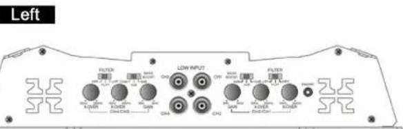
SPECIFICATIONS
| Model GZTA 4.24VDC | |
| RMS Power @ 4 Ohm @ ≤1% THD+N | 4 x 120 W |
| RMS Power @ 2 Ohm @ ≤1% THD+N | 4 x 200 W |
| RMS Power @ 2 Ohm @ ≤10% THD+N | 4 x 235 W |
| RMS Power @ 4 Ohm bridged @ ≤1% THD+N | 2 x 400 W |
| RMS Power @ 4 Ohm bridged @ ≤10% THD+N | 2 x 470 W |
| T.H.D. <0.04% | |
| Signal / Noise Ratio > 60 dB | |
| Frequency response 10 Hz - 30 KHz | |
| Bass Boost +6 / +12 dB @ 50 Hz | |
| Lowpass filter 50 - 250 Hz | |
| Highpass filter 50 - 250 Hz | |
| Damping factor > 70 | |
| Input sensitivity 0,2-6 V | |
| Operation voltage 24 V | |
| Fuse 2 x 40 A | |
| Dimensions L x W x H mm Inch | 440 x 263 x 55 17.3 x 10.4 x 2.2 |
PRECAUTIONS
Use speakers with an impedance of 2-4 Ohms
-
Avoid installing unit where:
-
It would be subject to high temperatures, such as from direct sunlight or hot air from the heater.
It would be exposed to rain or moisture.
It would be subject to dust or dirt.
If your car is parked in direct sunlight and there is a considerable rise in temperature inside the car, allow the unit to cool off before operation.
- This power amplifier employs a protection circuit to protect the transistors and speakers if the amplifier malfunctions. Do not attempt to test the protection circuits by covering the heat sink or connection improper loads.
Do not use the unit with a weak auto battery as its optimum performance depends on a normal battery supply voltage.
FUSE REPLACEMENT
If the fuse blows, check the power connection and replace the fuse. If the fuse blows again after replacement, there may be an internal malfunction. In this case, consult your dealer.
WARNING:
Use the specified amperage fuse. Use of a higher amperage fuse may cause serious damage. PROTECTION CIRCUIT:
This amplifier is provided with a protection circuit which operates in the following cases when the unit is overheated or the speaker terminals are short circuited.
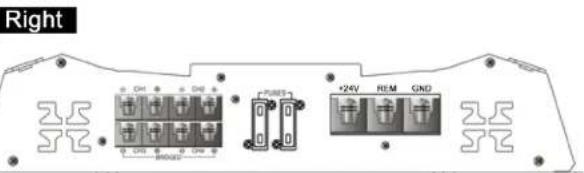
WIRING INSTRUCTIONS
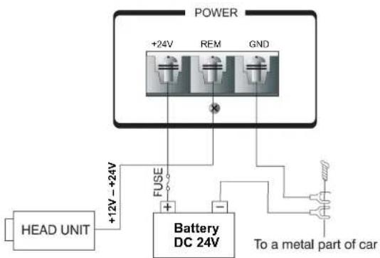
o POWER CONNECTION
The battery terminal (BATT) must be connected directly to the positive terminal of the vehicle battery to provide an adequate voltage source and minimize noise. Connecting the battery terminal lead to any other point (such as the fuse block) will reduce the power output and may cause noise and distortion. Use only #12 gauge or thicker wire for this lead and connect it to the terminal of the battery after all other wiring is completed.
GROUND CONNECTION
The ground terminal (GND) connection is also critical to the correct operation of the amplifier. Use a wire of the same gauge as the power connection (4.12 or thicker) and connect it between the ground terminal (GND) of the amplifier and a metal part of the vehicle close to the mounting location. This wire should be as short as possible and any paint or rust at the grounding point should be scraped away to provide a clean metal surface to which the end of the ground wire can be screwed or bolted.
- REMOTE TURN-ON CONNECTION
The amplifier is turned on by applying +24V to the remote turn-on terminal (REM). The wire lead to this terminal should be connected to the "Auto-Antenna" lead from the car stereo which will provide the +12V + 24V only when the car stereo is turned on.
SPEAKER CONNECTION
Wire the speakers depending on their type and number with the amplifier as shown below. For most operation possibilities a 1,5 - 2,5mm^2 cable is necessary.
STEREOWIRING DIAGRAM
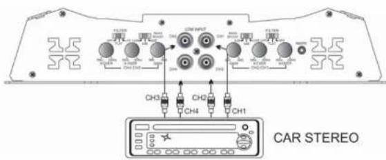
SPEAKER CONNECTIONS
Note that the two speakers & four speakers have been connected to the four terminals following the (+) and (-) graphic. Your speaker terminals may be marked (+) and (-) or there may be a red dot by one terminal which means the same as (+).
Connecting the speakers in this manner ensures that the two speaker cones will move in and out together according to the original recording. If one of the two speakers is reversed, stereo Imaging and bass response will be degraded.
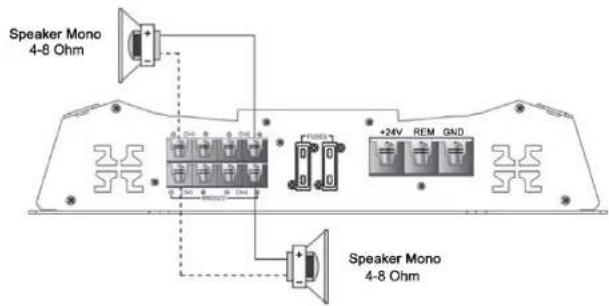
BRIDGED MODE
POWER CONNECTION LEADS
9
NOTES ON THE POWER SUPPLY:
Connect the +24V power input lead only after all other leads have been connected.
1. Be sure to connect the ground wire of the unit securely to a metal part of the car. A loose connection may cause a malfunction of the amplifier.
REM: The unit is turned on by applying +12 - +24 Volts to this terminal. This terminal does not draw heavy current like the two power terminals so a thinner connecting wire is acceptable. Standard 18 gauge is fine (standard colour: yellow). If the radio is equipped with a power antenna control wire, it can drive this terminal.
Place the fuse in the power supply lead as close as possible to the car battery (max. 30 cm / 11.81").
During a full power operation, maximum current will run through the system. Therefore, make sure that the leads to be connected to the +24V and GND terminals of the unit respectively must be larger than 10 gauge (AWG 10).
OPERATION
After the amplifier has been installed and all connections have been made carefully and securely, turn the radio on so that the amplifier is switched on automatically. After a short power-on period, the amplifier reaches its full performance. Now turn up the volume slowly using the volume control of the radio. If there is no sound or only a distorted replay, switch off the radio immediately – the amplifier will also switch off automatically – and check if all connections have been made correctly.
GAIN = INPUTLEVELCONTROL
The input level control allows the system to work well within a wide range of output level. Choose the adjustment in the way that you achieve a sound most possibly without any distortion. As a guideline the following procedure is recommended: Tune in the volume of your car radio to 2/3 of the maximum volume. Now turn the gain control of the amplifier from "Min" to "Max" direction until you can hear distortions. Then turn the level control a little back to "Min". The gain control adjustment is finished now.
X-OVER FREQUENCY CONTROL
A) When the crossover control is in the Low-pass position, this control becomes active allowing you to select your crossover point. For example: If you select 30Hz the amplifier will operate below 30Hz. If you select 250Hz the amplifier will operate below 250Hz.
B) When the crossover control is In the High-Foss position, this control becomes active allowing you to select your crossover point. For example: If you select 30Hz the amplifier will operate above 30Hz, if you select 250Hz the amplifier will operate above 250Hz.
CROSSOVER SWITCH
Flat: full range frequency
Low pass: the lower frequency under setting point can be pass. High pass: The higher frequency above setting point can be pass.
10
BASS BOOST CONTROLS
The amplifier has bass controls for making good sound combination.
FUSE
The amplifier is equipped with a plug-in auto fuse protecting the set against fault conditions. Do not use a fuse with a higher value and never bridge the fuse over, as this may lead to irreparability damage so that any claim for warranty is denied.
HOW TO PROCEED IN CASE OF FAULTS
| Symptoms Check Points Cure | ||
| No Sound | Is the POWER LED Illuminated? Check fuses in amplifier. Be sure Remote lead is connected. Check signal leads. Check again control. Check Tuner/Deck volume level. | |
| Is the Diagnostic LED illuminated? Check for speaker short or amplifier overheating. | ||
| Amp not switching on | No power to the amplifier Check power wire or connections. | |
| No power to remote wire with receiver on | Check connections to radio. | |
| Check fuse Replace fuse if broken. | ||
| No sound in one channel | Check speaker Leads Inspect for short circuit | cult or an open connection. |
| Check audio Leads Reverse left and right RCA Inputs to determine if it is occurring before the AMP. | ||
| Protection Lamp on | Temperature shut down Turn radio volume down. | |
| speaker wires shut | Separate speaker wires and insulate. | |
| Amp turning off on medium / high volume | Check speaker load Impedance The sure proper speaker load impedance recommendations are observed. (If you use an ohm meter to check speaker resistance, please remember that DC resistance and AC impedance may not be the same.) | |
Limited warranty - defective products must be returned in original packaging - please add a copy of the original purchasing invoice showing the purchasing date and a detailed description of the failure. Failure caused by overload, misuse or by using the product for competition purpose are not covered by the warranty.
wwwground-zero-audio.com
We reserve the right to make needed changes or improvements to the product without informing customer about this in advance.
Limited warranty - defective products must be returned in original packaging - please add a copy of the original purchasing invoice showing the purchasing date and a detailed description of the failure. Failure caused by overload, misuse or by using the product for competition purpose are not covered by the warranty.
wwwground-zero-audio.com
We neae the right to make raled change or improvement to the product without informing customers about this in advenoes.
Wb beho dns he hcht cme nge nce venerigeni ene veberenien an het product dor be oien erder de kien henvr te mcmeren.
GAIN = INPUT LEVEL Controle
Instellen van de ingangsgcvollighoid
Limited warranty - defective products must be returned in original packaging - please add a copy of the original purchasing invoice showing the purchasing date and a detailed description of the failure. Failure caused by overload, misuse or by using the product for competition purpose are not covered by the warranty.
wwwground-zero-audio.NL
We rere the right to mabe redal change or imprearmnt in the product without inforing customer shor this is in advance.
Wef behoienen hat nicht um die moglich erweiterend von befristeten man, het producte chart in vuren zeno dei klaer. Herewith ineminen. Nusire reo cie t d'entreprene et aven le rassifionment des modifiations ou des ambidantes ou producins en relation cierein.


- GROUND ZERO
- MOBILE ENTERTAINMENT
- PLEASE READ BEFORE INSTALLATION
- INTRODUCTION
- INSTALLATION INSTRUCTIONS
- COMMON FEATURES
- WARNING
- FEATURES
- SPECIFICATIONS
- PRECAUTIONS
- FUSE REPLACEMENT
- WARNING:
- WIRING INSTRUCTIONS
- o POWER CONNECTION
- GROUND CONNECTION
- - REMOTE TURN-ON CONNECTION
- SPEAKER CONNECTION
- STEREOWIRING DIAGRAM
- SPEAKER CONNECTIONS
- NOTES ON THE POWER SUPPLY:
- OPERATION
- GAIN = INPUTLEVELCONTROL
- X-OVER FREQUENCY CONTROL
- CROSSOVER SWITCH
- BASS BOOST CONTROLS
- FUSE
- GAIN = INPUT LEVEL Controle
Brand : Ground Zero
Model : GZTA 4.24VDC
Category : Car radio