Crossover CX 4 R - Car stereo CALIBER - Free user manual and instructions
Find the device manual for free Crossover CX 4 R CALIBER in PDF.
| Product Type | Active 2-way crossover |
| Brand | Caliber |
| Model | Crossover CX 4 R |
| Dimensions (W x D x H) | 260 x 160 x 38 mm |
| Weight | Approximately 1 kg |
| Power Supply | 12 V DC (terminal +12V, ground, remote control) |
| Fuse | 1 A (rated current) |
| Frequency Response | 10 Hz - 30 kHz ± 1 dB |
| Total Harmonic Distortion | 0.02% |
| Signal-to-Noise Ratio | > 100 dB (A-weighted) |
| Channel Separation | > 80 dB |
| Input Level | -12 dB to 12 dB (7 V - 0.2 V) |
| Input Impedance | 20 kOhms |
| Maximum Output Level | 15 V |
| Output Impedance | 50 ohms (balanced) |
| Low-Pass Crossover Frequencies | 60 Hz / 80 Hz / 100 Hz / 120 Hz (4-position selector) |
| High-Pass Crossover Frequencies | 80 Hz / 100 Hz / 120 Hz / Full-range (4-position selector) |
| Crossover Slope | 24 dB/octave |
| Graphic Equalizer | 7 bands (estimated) |
| Subsonic Filter | Yes, with on/off selector |
| Remote Control Included | Yes, model CXR for remote subwoofer level adjustment |
| Input and Output Peak LED | Yes (clipping indicators) |
| Delayed Remote Output | Yes (2-second delay) |
| Maintenance | Clean with a soft dry cloth. Avoid solvents. |
| Warranty | 12 months if installed by an authorized dealer, 30 days for self-installation |
Frequently Asked Questions - Crossover CX 4 R CALIBER
User questions about Crossover CX 4 R CALIBER
0 question about this device. Answer the ones you know or ask your own.
Ask a new question about this device
Download the instructions for your Car stereo in PDF format for free! Find your manual Crossover CX 4 R - CALIBER and take your electronic device back in hand. On this page are published all the documents necessary for the use of your device. Crossover CX 4 R by CALIBER.
USER MANUAL Crossover CX 4 R CALIBER
Thank you for choosing a Caliber product. In doing so you've demonstrated a desire to own the finest in Car Audio Technology. Caliber strives to provide you with the finest products possible, and is always looking for ways to please our customers even more.
Properly installed, your Caliber CX4R will provide years of high quality sonic reproduction. Before installing this 4-way crossover in your vehicle, please read this entire manual carefully, in order to protect your vehicle, and get the maximum performance of your mobile sound system.
Caliber Warranty
Due to the complexity of our products, we strongly recommend that this 4-way crossover is installed by your authorized Caliber dealer. If properly installed by your dealer we provide a warranty for 12 month from the date of purchase. If you install this 4-way crossover yourself, we wish you lots of fun and success in doing so. If you follow our guidelines, you'll get the best result. Our warranty, however, will be limited to and not exceed 30 days from the date of purchase.
Caliber Accessories
To realize the exceptional performance of which this 4-way crossover is capable, it is necessary that power sources, signal sources, speakers and interconnects are of the highest quality. Remember that Caliber is a specialized manufacturer of all sorts of Car Audio components. We also manufacture everything needed for the 'optimal' Car Audio System (except the car). So be sure to 'Get Connected' with Caliber and ask your local Caliber dealer for our accessories.
Important
The quality of installation may effect the performance and reliability of a Caliber CX4R 4-way crossover. If you have any doubts or questions regarding installation or use, don't hesitate to contact your official Caliber dealer. A Caliber dealer is selected for his knowledge in auto sound, and has been trained to give you great advice and service. You can always count on him to give you advice for any technical problems and will keep you informed on the latest products by Caliber.
Wewish you lots of enjoyable moments with your newest toy. Adjust the sound to perfection, but keep paying attention to the road whilst doing so.

Specifications CX4R
Frequency response 10Hz to 30KHz ±1dB T.H.D. 0.02%
Signal to noise ratio >100dB Channel separation >80dB
Input level -12dB to 12dB (7V to 0.2V)
Input impedance 20K
Maximum output level Output impedance
15V
502 Balanced
Crossover slope 24dB/Oct
Fuse rating
IA
Dimensions W x L x H (mm)
260× 160× 38(mm)
Features CX4R (See illustration on the inside cover)
I Input
Docking ports for the RCA connectors arriving from the source unit's output. If you choose for a two channel input, connect the RCA's to the dockingports 1A, and switch the input selector-switch(1C) to the single position. If you decide to use the four channel input option, connect both the RCA dockingports 1A and 1B, and switch the input selector-switch(1C) to the dual position. In case you use a four channel input, you can still use the feder adjustment from your headunit.
2 Input Level Control
This Input sensitivity control allows you to adjust the input sensitivity to the output of your source unit, in order to get a maximal signal transmission.
3 Subsonic filter On/Off Switch
This switch allows you to switch on or off the Subsonic filter. The Subsonic filter filters the lowest (non musical) frequencies out, which will make your speakers (especially your woofers) sound more naturally.
4 Subsonic Frequency Adjustment
The subsonic frequency adjustment allows you to adjust the frequency which is filtered by the subsonic filter. By adjusting this frequency (between 10 - 40Hz ) to the frequency-range of your subwoofer, you can get an optimal result.

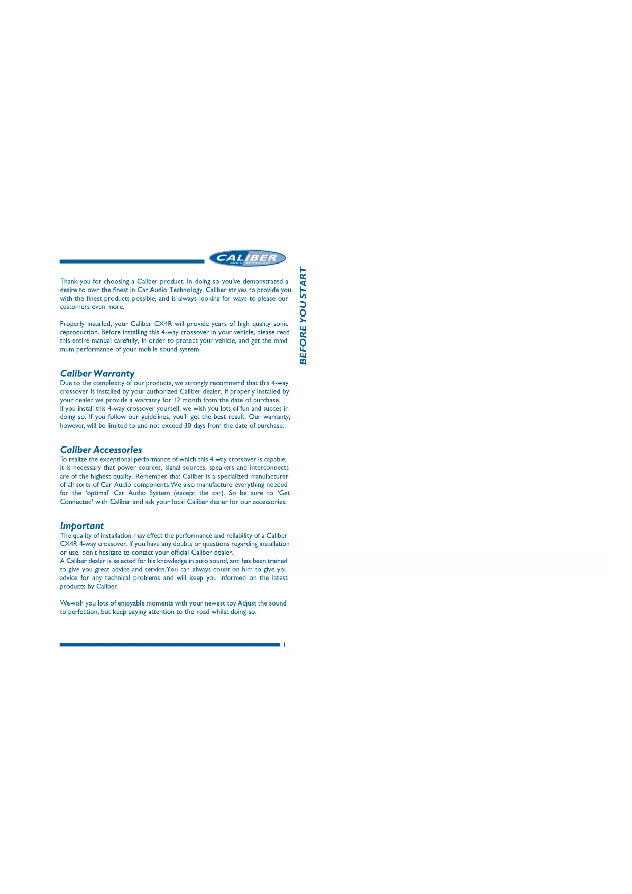
5 Power Terminals
" ^ 十 + ^ 一 Connect to the vehicle's positive 12V supply (+12V DC)
" = "Connect to the vehicle's ground (-12V DC)
"R" Connect to the head unit's remote turn on leads.
"D/R" Delayed Remote output. Connect to all the amplifiers following the CX4R. This will delay the turn on of these units by 2 seconds after the system is powered up.
6 Remote Low Pass Level Control
Docking port for the jack of the supplied CXR Remote control. This gives you the possibility to adjust your Low Pass Level on dash.
7-10 Output Level Controls
These allow you to adjust the output levels of all 4 different channels. Because not all speakers (tweets, woofers) have the same sensitivity, the output level has to be adjusted, so the overall volume will be the same for all speakers.
II Band Pass Mono/Stereo Switch
This switch gives you the opportunity to set the Band Pass output in a mono or stereo mode. This can be very useful if you use the Band Pass output for your rearfill or as a centerchannel.
12 Low Pass Phase Switch
This switch allows you to turn the phase of the Low Pass channel 0^ , 90^ or 180^ . This option can be helpful when your subwoofoers are places further away as the rest of your speakers. This creates significant phase differences which make you hardly hear any low-reproduction in the driversseat. By turning the phase of the low pass signal, you can correct the sound level of your Low Pass.
13 Low Pass Mono/Stereo Switch
With this switch you can choose whether to have your subwoofer(s) (Low Pass) play in mono or stereo mode. We advice you to always let your woofers play in mono-mode, especially when there is more than one woofer in an enclosure.
14 Band Pass/High Pass Selector
In some installations two High Pass outputs are desirable. This selector switch enables you to make a second High Pass output from the third channel.
CALIBER
15-20 Modulair Resistor Units
These 16-pins modulair resistor units are what it is all about with the CX4R. They allow you to create a really personal sound, which is especially tuned for your installation. By changing the resistor value of these units, you can determine your own crossover frequency per channel. The sequence of these resistor units is shown in the graphics below them. So, module 1 (15) is for the High Pass side of your Band Pass channel, and module 2 (16) is for the Low Pass side of your Band Pass Channel, and so on.
By giving all the modules your own resistor value (and thus their own bandwidth) you can tune your installation to perfection. How you can calculate the resistor values for each frequency is demonstrated in a separate chapter.
21 Clipping LED's
These clipping LED's will warn you when an output is clipping. When they lit up continuously the output is clipping, and you should immediately adjust the outputlevel, or you will damage your speakers. When these LED's start to flicker, the output is almost clipping. This is a warning sign for you to take extra care to the output level.
22 Outputs
Docking ports for the RCA cables which lead to the various amplifiers.
Mounting your CX4R
Find a steady, secure area to mount your CX4R. Be sure it is accessible, but not in an area where the adjustments may be bumped by accident. Use the chassis of the CX4R as a template and mark the locations of the mounting holes.Predrill the mounting holes using a 2.5 mm diameter drill bit and use the screws supplied with your CX4R to fasten your 4-way crossover. Make sure the screws are tightened securely.
Getting your power started
REMEMBER TO ALWAYS DISCONNECT BATTERY GROUND BEFORE WORKING ON A VEHICLE'S ELECTRICAL SYSTEM
- First, the +12V terminal is connected. The +12V terminal is the first slot(A) from the left of the powerconnector. Use the same +12V source as you are using for your amplifiers, in order to avoid picking up noise due to voltage differences.
Don't forget to add an inline fuseholder holding a IA fuse at the beginning of the powercable for the CXQ20. This to protect both your vehicle and audiosystem in case of a short.
CALIBER
- Second, the -12V ground terminal must be connected. The -12V ground is the second slot(B) from the left of the powerconnector. This cable has to be fastened securely to the chassis of the vehicle with the same gauge cable as the positive cable (the same amount of power has to run through it). Preferably you should have the same ground connection for your entire system. Ensure that all paint, undercoating or any other insulation is removed from the area where you want to make your ground connection to.
- Third to connect is your remote turn-on. The R (remote turn on) is the third slot(C) from the left of the powerconnector. Many radio-cassette and CD-players have an output terminal for connection of the Remote turn on. If you don't have such an output, a separate switch must be installed to control your remote on/off functions.
- The last terminal to connect is your Delayed Remote output. The D/R (Delayed Remote output is the first slot (D) from the right of your powerconnector. The delayed remote output should be connected to all the amplifiers and other equipment following the CX4R, so they can be started with a 2 seconds delay.
Signal input
The next to connect is your signal input. Choose the correct length and style of RCA patch cables for your needs. Better RCA's, such as the ones from the Caliber CL 600 and CL 800 Get Connected Series, have gold-plated connectors and multiple layers of shielding for better noise rejection. These twisted cables give a better result in combination with the balanced outputs. (Consult your official Caliber dealer about these cables and RCA's).
Be extra careful when running your RCA patch cables. Car environments are notorious for poorly insulated wires. This means that hiss, engine noise and fan noise can easily be picked up trough RCA cables, if ran incorrectly. As a precaution, avoid placing your RCA's near large wire looms and electronic fans whenever possible.
Connect the patch cables to the RCA output of your source unit. Run the RCA cables to the location of the CX4R, and connect them to the input RCA connectors of the CX4R. Be sure to connect the right channel to the right channel, and the left to the left. (In an audio system the right always has red RCA connectors, and the left RCA connectors are white or black).
Signal output
Once you have connected the inputs, it is time to connect the outputs. Be careful to connect, via RCA patch cables, the correct output to the correct amplifier. Take good care in the balance of your signal (Right to right, and left to left). Now that you have connected all your signal and power cables, it is time to connect your battery again, and place the IA fuse in the fuseholder.

Crossoverpoints (resistor unit values)
Determining the best crossoverpoints (= resistor unit values) for your speakers is critical. The size of the speakers, their powerhandling characteristics and frequency range have to be taken into consideration. Also the location of the speakers has to be evaluated before the best crossoverpoints can be chosen. A good ear, and preferably some advice from your official Caliber dealer can help you a lot when you are adjusting your crossoverfrequencies.
How to calculate the correct resistor value for a desired crossover-frequency.
$$ R (K i l o - O h m) = \frac {7 2 0 0}{F r e q u e n c y (H z)} $$
Example: Desired crossover-frequency = 72Hz
$$ R (K i l o - O h m) = \frac {7 2 0 0}{7 2 \mathrm {H z}} = 1 0 0 K \Omega $$
To make your own value resistor units, you will need a 16-pins module and the required resistors to come to the calculated resistor unit value.
| Frequency R (Kilo-Ohm) | Frequency R (Kilo-Ohm) |
| 20Hz 360KΩ | 1300Hz 5,6KΩ |
| 30Hz 240KΩ | 1550Hz 4,7KΩ |
| 40Hz 180KΩ | 1800Hz 3,9KΩ |
| 50Hz 150KΩ | 2000Hz 3,6KΩ |
| 60Hz 120KΩ | 2200Hz 3,3KΩ |
| 70Hz 100KΩ | 2500Hz 3,0KΩ |
| 80Hz 91KΩ | 2700Hz 2,7KΩ |
| 90Hz 81KΩ | 3000Hz 2,4KΩ |
| 100Hz 75KΩ | 3200Hz 2,2KΩ |
| 125Hz 56KΩ | 3500Hz 2,0KΩ |
| 160Hz 47KΩ | 4000Hz 1,8KΩ |
| 200Hz 36KΩ | 4500Hz 1,6KΩ |
| 250Hz 30KΩ | 5000Hz 1,5KΩ |
| 316Hz 22KΩ | 6000Hz 1,2KΩ |
| 400Hz 18KΩ | 7000Hz 1,0KΩ |
| 500Hz 15KΩ | 7500Hz 0,96KΩ |
| 630Hz 11KΩ | 8000Hz 0,91KΩ |
| 800Hz 9,1KΩ | 9000Hz 0,81KΩ |
| 1000Hz 7,5KΩ | 10000Hz 0,75KΩ |
Given resistorvalues are the standard values of the E12 resistorseries.

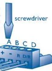
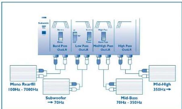
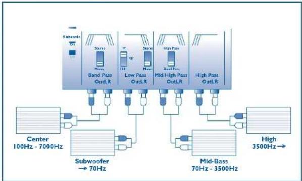
We will give you three examples of how you can set up a system. Take good care in the position of the various switches. In all the system set-ups we show you, the subsonicfilter is in its "on" position.

Checking the level settings once more
Now that you've had your fun in tuning your system to your likings, it is time to check the output levels of your CX4R once again. Since you have been playing with power, in cutting or boosting certain frequencies, the output level may have been affected. Play a dynamic track you know very well, turn the volume on your radio to 3/4 of the maximum and adjust the outputs accordingly. If distortion is heard, or the Clipping LED's are illuminating, turn your output levels down. If on the other hand you have a drop in volume now, you can very slowly increase the output levels as long as the Clipping LED's do not illuminate.
BE CAREFUL NOT TO OVERDRIVE YOUR AMPLIFIERS
The Caliber CXR Sub-woofer Level Remote Control
Now here is an accessory which came with your CX4R that you are going to have a lot of fun with. It gives you the complete control over your sub-woofer level, from the front seat of your vehicle, and allows you to adjust the amount of bass to the type of music you are playing.
The CXR Remote Control is easy to mount and comes with a 5 meter cable with clip on telephone jacks at both sides. It will take you about 10 minutes to install this Remote control on your dashboard.
After you have plugged in your telephone jacks in the remote control and the CX4R, you must turn up the Low Pass output level a little.
And now: Start your engine, turn on your audio, crank up the volume, pay attention (to the road), sit back, relax and enjoy your new Caliber sound system.