
RMB795 - Thermostat SIEMENS - Free user manual and instructions
Find the device manual for free RMB795 SIEMENS in PDF.
| Product type | HVAC control unit |
| Brand | Siemens |
| Model | RMB795 |
| Power supply | 24 V AC (typical for Siemens devices) |
| Display | LCD screen with symbols and text |
| Control elements | Navigator button OK, ESC key, INFO key, fault key |
| Main functions | Time scheduling, Comfort/Precomfort/Economy/Protection modes, exception and holiday management, trend recording, fault display |
| Number of room groups | Up to 10 groups |
| Number of ambient modes | 4 (Comfort, Precomfort, Economy, Protection function) |
| Number of holiday periods | Up to 16 per group |
| Number of exception days | Up to 16 per group |
| Number of daily switching operations | Up to 6 per day |
| Program memory | Retained in case of power failure |
| Maintenance and cleaning | Clean with a soft dry cloth. Do not use liquids. |
| Safety | Installation and commissioning by qualified technician only. Integrated frost protection. |
| General information | Manual available in French, German, English, Dutch and other languages. |
Frequently Asked Questions - RMB795 SIEMENS
User questions about RMB795 SIEMENS
0 question about this device. Answer the ones you know or ask your own.
Ask a new question about this device
Download the instructions for your Thermostat in PDF format for free! Find your manual RMB795 - SIEMENS and take your electronic device back in hand. On this page are published all the documents necessary for the use of your device. RMB795 by SIEMENS.
USER MANUAL RMB795 SIEMENS
Languages not required can be removed
natural_image
Close-up of a Siemens industrial control panel with no visible text or symbols on the device itself.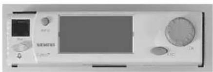
natural_image
Front view of a medical or laboratory device with control buttons and display (no visible text or symbols)Inhalt
natural_image
Close-up of a Siemens air conditioner unit with control knobs and a screen (no visible text or symbols on the device itself)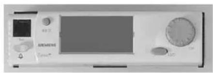
natural_image
Front view of a medical or laboratory device with control panel and display (no visible text or symbols)Contents
The operating elements.... 3
The display 4
The symbols on the display 5
Navigating through the menu....6
Selecting the room groups' operating modes....8
Do you want to operate the plant according to the time program? 9
You don't want to operate the plant according to the time program....10
What room temperature can you set?....11
Do you want to query the plant's operating state in a room group?......12
Do you want to view the current operating state of the reference rooms? 13
Do you want to have the current plant data displayed? . 14
Do you want to readjust the time of day or the date?..... 15
Do you want to change the daily heating / cooling periods? 16
Do you want to enter holiday periods? 18
Do you want to enter special days? 19
Do you want to display the recording of measured values? 20
Do you want to access a specific RXB room controller? 21
A fault has occurred.... 23
What information is required by your HVAC engineer?.. 24
Saving energy without sacrificing comfort 25
Please note that these Operating Instructions cover all technical features of your controller. However, depending on the type of plant, not all functions are necessarily active. In case of doubt, please contact your HVAC engineer.
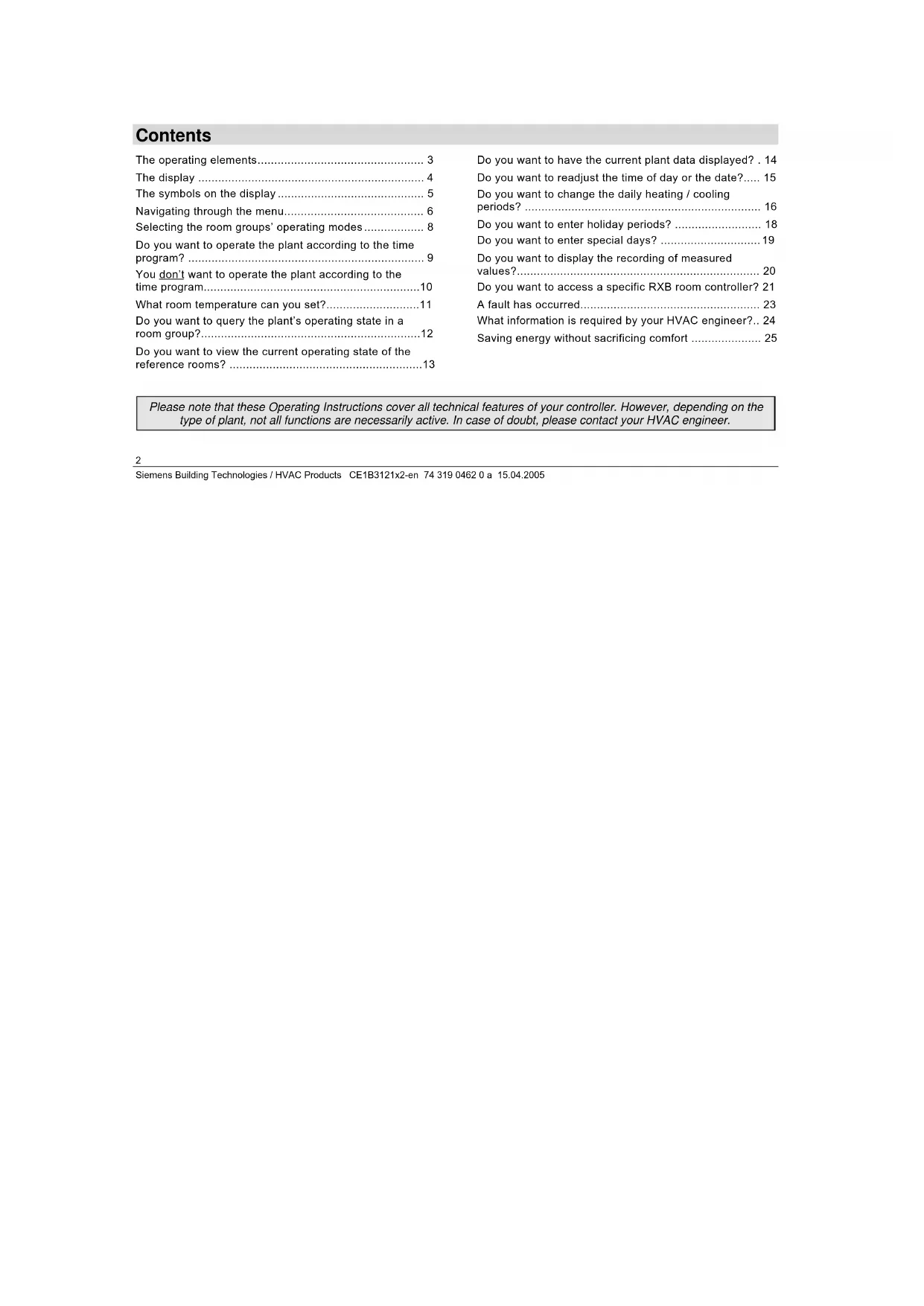
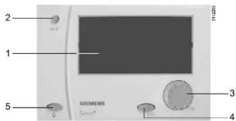
The operating elements
Plug-in type operator unit
Detached operator unit
1 Display
2 INFO button
Function 1: Display of key plant data Function 2: Display of information about the individual datapoints on the current menu
3 OK select-and-press knob
Turn: Selection of values menu options or adjustment of
Press: Confirmation of menu options or settings
4 ESC button
Returning to the previous menu
5 Fault button with LED
LED lit / flashes: Indication of fault Press: Acknowledgement of fault or reset
The display
The symbols on the display
| Symbol | Meaning Symbol Meaning | ||
| 1 | Room group with room group numberHere: Room group 1 | Trend recording of a measured value with trend channel number. Here: Trend channel 1 | |
| Auto | Automatic operation according to the time program | Holidays | |
| Room operating mode "Comfort" / | Special day | ||
| p | Room operating mode "Precomfort" | Help display – information about the selected data point | |
| Room operating mode "Economy" / | |||
| @ | Protection | Info level – display of key plant data | |
| DHW optg mode "Normal" | Setting level – display and adjustment | ||
| DHW optg mode "Reduced" | Please wait – searching | ||
| DHW optg mode "Protection" | Fault |
The service engineer may have overwritten the submenu names "Room group 1...10" and "Trend channel 1...4" used in these Operating Instructions with clear-text names when commissioning the plant!
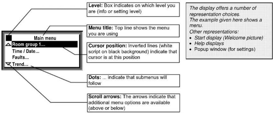
Navigating through the menu
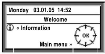
Start display:

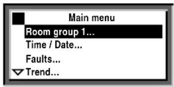
Main menu

Introduction
These Operating Instructions assist you in operating the controller in all standard situations (Do you want ... etc., starting on page 9).
The Operating Instructions always give you the Path you need to follow through the menu to reach the relevant function – from the start display to the adjustable value.
Start display
When not operated, the display always shows the start display – unless a fault has occurred.
- Press the OK select-and-press knob:
The list of menus appears.
Main menu
- Turn the OK knob: The cursor advances from one line to the next.
- The selected line appears with black background and inverse text.
- Select the required option.
- Confirm your choice by pressing the OK knob.
Submenu:

Setting the numerical value:
Submenus
- Now, you are on the submenus.
- The 3 dots (...) after the text indicate that additional submenus will follow.
- Follow the indicated path by turning the OK knob to find the option, then push to confirm.
- At the end of the path you will reach the adjustable value.
Setting the numerical value
- The numerical value appears as a pop-up window.
- Adjust the value by turning the OK knob.
- Then, confirm the value by pressing the OK knob.
- The cursor now advances to the next value to be adjusted, or returns to the datapoint if there is no other value to be adjusted.
- By pressing the ESC button, you return to the entry box or menu choice you have previously quit.
- Pressing the ESC button several times takes you back to the start display.
With the majority of menus, you can display information about the option currently selected.
For that, press the INFO button.
Selecting the room groups' operating modes
The ventilation / air conditioning plant was switched on by your HVAC specialist.
On submenus Room group 1...10 > Room operating mode..., he selected Auto, which acts on the relevant room group.
In that case, that room group operates automatically.
The control system switches automatically. Reasons can be:
• Yearly or 7-day time switch program
• Interventions via a room unit
- Night cooling
- Fire alarm off
- Smoke extraction
• External commands via the signal inputs
Path: Welcome > Main menu > Room group 1... > Room operating mode... > Preselection: > ...
Do you want to operate the plant according to the time program?
In room operating mode ② the central control unit operates according to the time program.
Time program
The time program contains the start time and the associated room operating mode (room setpoint) for all phases of 24-hour heating / cooling operation. The time program has been entered in your central control unit. To satisfy your individual needs, you can change the entries made (page 16).
Example of a time program
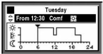
From 06:00: Comfort mode
From 11:30: Precomfort mode
From 12:30: Comfort mode
From 17:00: Precomfort mode
From 19:00: Economy mode
You don't want to operate the plant according to the time program
Other room operating modes
If you don't want to use the time program (that is, no automatic operation of plant), choose one of the following room operating modes from operating line
Preselection:
| Comfort | Plant ON, heating / cooling to the Comfort setpoint | |
| Precomfort | Plant ON, heating / cooling to the Precomfort setpoint | |
| Economy | Plant OFF, unoccupied mode heating / cooling to the Economy setpoint; night cooling and frost protection function activated | |
| Protection | Plant OFF, frost protection function activated |
Setpoints
The setpoints assigned to the room operating modes use the same symbols and designations.
Settings: pages 11.
Path: Welcome > Main menu > Room group 1... > Room operating mode... > Preselection: > ...
If you want to heat / cool temporarily with a «Continuous operating mode», don't forget to return to AUTO mode in due time!
What room temperature can you set?
Your central control unit offers 4 room operating modes. Each operating mode are assigned 2 temperature set-points (heating and cooling).
Depending on the selected room operating mode, your central control unit changes the setpoints according to a time program (page 9).
The following setpoints are available. The default values represent the recommended setpoints.
You can change the setpoints to suit your individual needs.
| Symbol | Operating mode | Impact on the room? Guide value*Heating Cooling | ||
| ☀️ | Comfort This is the operating mode for the occupied space. It ensures comfortable conditions | 21 °C | 24 °C | |
| ☒ | Precomfort This is an energy-saving operating mode for the space to ensure that comfortable conditions will be reached quickly when changing to Comfort mode | 19 °C | 28 °C | |
| ☒ | Economy Plant OFF. A minimum / maximum temperature is ensured in the space (unoccupied mode) | 15 °C | 30 °C | |
| ☒ | Protection | Plant OFF. Frost protection active | ---- | ---- |
* = factory settings
Path: Welcome > Main menu > Room group 1... > Room temp setpoint...
Do you want to query the plant's operating state in a room group?
If, during automatic heating / cooling operation, you want to know your plant's current operating state (the room operating mode), go to the Info level:
- Go back to the start display by pressing the ESC button.
- Press the INFO button or turn the OK knob.
The room operating state is displayed as follows:
| Room group 1 | |
| Operating mode: | Comf |
| Cooling setpoint: | 24.0 °C |
| Heating setpoint: | 21.0 °C |
| Cause: | Time switch |
Meaning:
Operating mode:
Here, the currently active room operating mode is displayed. In this example, it is room operating mode ⚙Comf for room group 1.
Cooling setpoint:
Here, the Comfort setpoint of cooling is displayed.
Heating setpoint:
Here, the Comfort setpoint of heating is displayed.
Cause
Here, the cause for the current operating state is given. Possible reasons:
- Operating mode switch (manual changeover)
- Operating mode selector (manual changeover)
• Occupancy button on the room unit - Timer button on the room unit
- Special day
- Holidays
- Time switch of the time program (in the example shown)
Do you want to view the current operating state of the reference rooms?
This means for room group 1 in our example:
Reference rooms 2 and 3:
Here, the current room temperature can be read off. In our example, 22 °C in reference rooms 2 and 3.
Highest room temp:
Here, the highest room temperature within the selected room group can be read off. In our example, 23 °C.
Lowest room temp:
Here, the lowest room temperature within the selected room group can be read off. In our example, 21 °C.
Path: Welcome > Main menu > Room group 1... > Room temp actual value...
Do you want to have the current plant data displayed?
If you are on the start display (welcome picture), you only have to press the INFO button or turn the OK knob and you will be on the information level 1. Here, you find the key plant data listed.
Please note: The display depends on the type of plant. You cannot change any values here!
Now, press the INFO button or turn the OK knob. This will take you from one info page to the next.
The ESC button will take you straight back to the start display.
You can display the following data, for example:
• Room operating mode (state, reason) per room group
• Time switch per room group
- Various data (e.g. outside temperature)
You reach the Info page only from the start display! However, if you press the INFO button while one of the menus is displayed, it is not the current plant data that appear, but a help display for each datapoint with the cursor. The help display shows the path you have followed thus far and the correct datapoint name.
Do you want to readjust the time of day or the date?
Time of day / date
All data of the yearly time switch in your central control unit were entered when your plant was commissioned. If readjustments are required, use the Time of day / date menu.
Summer- and wintertime
The same is true if you need to readjust the dates for the start of summer- and wintertime.
Note: Do not enter the actual dates of changeover but - in accordance with international standards - the earliest possible dates for the start of summertime and winter-time!
The Time of day / date menu includes:
• Time of day (e.g. 09:53)
- Date (e.g. 25.07)
• Year (e.g. 2005)
• Summer time start (e.g. 25.03.)
• Winter time start (e.g. 25.10.)
Path: Welcome > Main menu > Time of day / date...
The change from wintertime to summertime, and vice versa, takes place automatically!
Do you want to change the daily heating / cooling periods?
General
In the time program, you can set the daily heating / cooling periods to suit your individual needs. Each day can accommodate a maximum of 6 switching points; a room setpoint is assigned to each time period. In addition to the weekdays (Monday through Sunday), you can program a special day, that is, a special 24-hour heating / cooling program. The special day will be activated when you make an entry on the Holidays / special days menu (page 18). Changes on the central control unit can only be made if the heating program is predefined by the time switch in the controller. If the program is defined by an external operator station, changes to the program can only be made from that station.
Before making entries, please observe
- First, always enter the start time of the heating / cooling period, then the room operating mode for that period
- You have the room operating modes ⚙, p; and ① to choose from. Set the setpoints on menu Room temp setpoint... (page 11)
- You can copy any 24-hour heating / cooling program to other days ( page 17)
Changing and canceling times and setpoints
- Select the required day.
- In the diagram, advance pointer ▼ to the point in time to be changed.
- Set the required time. Reset the time via 00:00 until ---:--- appears.
- Select the required operating mode.
- If required, set additional times and select additional setpoints.
Path: Welcome > Main menu > Room group 1... > Time switch...
Entering additional switching points
- Select the required day.
- In the diagram, advance pointer ▼ to the last point in time of the current program.
- Turn the OK knob by one notch;
--:-- —— appears. - Set the required start time.
- Select the required room operating mode.
Copying a time program within the same week
- Select the day to be copied.
- Turn the OK knob in clockwise direction until Copy to: appears.
- Press the OK knob.
- The menu with the selection of days (week section, individual weekdays, special day) appears.
- Select the required weekday or week section.
- Copy (press the OK knob).
Copying a time program to other room groups
- Select the day to be copied.
- Turn the OK knob in clockwise direction until Copy to: appears.
- Press the OK knob.
- The menu for selection of the room groups (All room groups, Room group 1...10) appears.
- Select the required room group.
- Copy (press the OK knob).
New 24-hour program
The central control unit is supplied with a 24-hour program entered for every day (incl. special day). This means that you never have to create a new 24-hour program, but only change an existing program.
Power off – heating / cooling program lost?
In the event of a power failure, the 24-hour programs entered will be maintained, independent of the duration of the power failure.
First, prepare a 7-day schedule for the daily switching times and operating modes – this will facilitate entry into the central control unit!
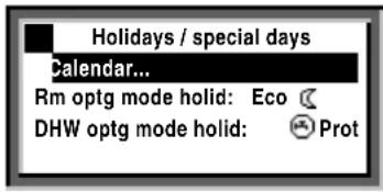
Do you want to enter holiday periods?
For each room group, you can enter 16 holiday periods on your central control unit. During a holiday period, there is no heating program active but only the same room operating mode or DHW operating mode.
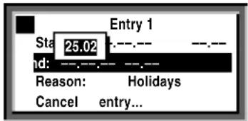
Date
On the submenus Entry 1, Entry 2, Entry 3, etc., you need to enter for each holiday period:
- Menu option Start: The date, year and time of day of the first day of the holiday period
- Menu option End: The date, year and time of day of the last day of the holiday period
- Menu option Reason: The holidays
Every entry can be deleted (menu option Cancel entry).
Room operating mode
Enter the required room operating mode with menu option Rm optg mode holid. Available are Economy or Protection. The entry will apply to all holiday periods.
DHW operating mode
Enter the required DHW operating mode on operating line DHW optg mode holid. Possible are Auto, Normal Reduced and Protection The entry will apply to all holiday periods.
Path: Welcome > Main menu > Room group 1... > Holidays / special days > Calendar... > Entry 1...
Path: Welcome > Main menu > Room group 1... > Holidays / special days > Rm optg mode holid:
Path: Welcome > Main menu > Room group 1... > Holidays / special days > DHW optg mode holid:
Before making entries, prepare a yearly time schedule for all holiday periods!
Do you want to enter special days?
For each room group, you can enter 16 special days on your central control unit.
During the special days, it is not normal heating / cooling program of heating / cooling operation that is active, but the operating modes according to the special day program.
Date
On the submenus Entry 1, Entry 2, Entry 3, etc., you need to enter for each special day:
- Menu option Start: The date, year and time of day of the special day
- Menu option End: For 1 special day: Confirm the data that appear in the popup window. For 2 or more successive special days: The date, year and time of day of the last special day
- Menu option Reason: The special day
Path: Welcome > Main menu > Room group 1... > Holidays / special days > Calendar... > Entry 1...
Every entry can be deleted:
Select and confirm menu option Cancel entry...
Heating / cooling program
Enter the heating / cooling program for the special days on the Time switch menu (page 16). It will apply to all special days.
Before making entries, prepare a yearly time schedule for all special days!
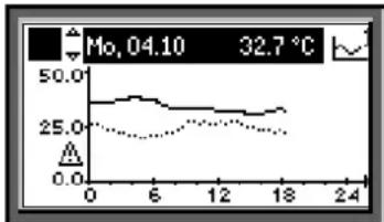
Do you want to display the recording of measured values?
Using the Trend... menu, the progression of a maximum of 4 measured values (Trend channel 1...4) can be displayed. The trend function offers the following choices of measured value recording:
Over the last 8 minutes, 8 hours, 24 hours or last 6 days.
Display of measured value recording:
- Select the Trend... menu
- Choose the required Trend channel 1...4 or the measured value in clear-text. The 24-hour view of the current day appears
Navigating through the views:
- Turn the OK knob counterclockwise to show the previous day, and clockwise to show the next day
- Having the current 24-hour view displayed, turn the OK knob clockwise to show the last 8 hours. Turn clockwise again to reach the view of the last
- 8 minutes, and counterclockwise to go back again
- If you want to return to the previous menu, press the ESC button.
Recording of measured value looks as follows:
line
| Time | Value | |------|-------| | 0 | 32.7 | | 6 | ~30 | | 12 | ~28 | | 18 | ~25 |Path: Welcome > Main menu > Trend... > Trend channel 1...
This function is only available if the plant is appropriately designed and the necessary settings on the central control unit have been made by the service engineer when commissioning the plant!
Do you want to access a specific RXB room controller?
Select the required RXB room controller:
- Select the Operation RXB... menu
- Enter the number of the geographical zone per Geogr zone(ap), Geogr zone(room) of the RXB you wish to access
- Then, select the RXB device data... menu
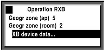
Path Welcome > Main menu > Operation RXB... > RXB device data...
The following information about the RXB room controller is displayed:
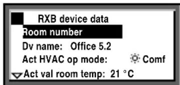
Meaning:
Room number:
This is the number of the room in which the RXB room controller is located. In our example: Room number 110.
Device name:
The device name identifies each individual RXB room controller. In our example: Office 5.2.
Active HVAC operating mode:
Here, the currently active room operating mode is indicated. In our example, the RXB room controller uses room operating mode ⚙ Comf.
Actual value room temp:
This is the current room temperature of the selected room. In our example: 21 °C.
Current room temp setpoint:
This is the current room temperature setpoint of the selected room.
A fault has occurred
If a fault occurred in the plant, it will appear on the display. In addition, the LED inside the 🔔 button will flash or will be on. Proceed as follows
LED flashes:
- Press the button to unlock.
- If the LED keeps flashing, the fault still exists or the button must be pressed again to unlock.
LED lit:
- Rectify the fault.
- If the LED is still lit, the 🔔 button must be pressed again to unlock.
Unlocking is possible only after the cause of fault has been removed.
If you cannot rectify the fault, contact your HVAC engineer.
Additional information about the display of faults:
Faults current menu
Here, you can see which faults are currently present.
The following information about each fault is displayed:
• The cause (e.g. pump 1)
- The error code (important for the HVAC engineer)
- The date and the time of day the fault occurred
Fault history menu
Here, each of the last 10 faults will be listed. The information given is the same as that provided with current faults.
Fault status message bus menu
If your plant contains several interconnected devices, the central control unit will display faults of other devices.
Fault indication on the setting level
If you keep the ESC button depressed for 2 seconds, the current fault will be displayed.
Path: Welcome > Main menu > Faults...
What information is required by your HVAC engineer?
Your Central control unit has characteristic data that enable your HVAC engineer to offer support, to answer your questions about the plant, etc. You find these data on the submenu Device information....
Controller
| Menu option Explanation, example | |
| File | B |
| Software version of the central control unit | |
| Hardware version of the central control unit | |
Path: Welcome > Main menu > Device information... > Controller...
Saving energy without sacrificing comfort
- During the day, do not allow the room temperature to exceed 21 °C when heating. Each additional degree increases heating costs by 6 to 7 %
- During the day, do not allow the room temperature to fall below 24 °C when cooling. Each degree below that level increases cooling costs
-
Guide values for room temperatures in living and working spaces:
– During the day in the heating period:
Precomfort = 19 °C, Comfort = 20...22 °C
– During the day in the cooling period:
Precomfort = 28 °C, Comfort = 22...24 °C
– During the night in the heating period:
Economy = 14...18 °C. Protect objects sensitive to low temperature, such as plants!
– During the night in the cooling period:
Economy = 29...31 °C -
Ensure that there are no curtains, furniture or other objects in front of or behind air inlets and outlets. They have an impact on air circulation and can cause drafts
- Closed shutters and blinds reduce heat losses
- Closing blinds in due time during the cooling season reduces the impact of solar radiation, thus saving cooling costs
- Make sure air filters are checked and replaced at regular intervals
If your plant uses a room unit with temperature and humidity sensor, it should not be exposed to thermal and moisture disturbances since these affect the control function. For this reason, following applies to the reference room where the room unit is located:
- Avoid drafts through open doors
- Avoid heat gains from people, machines and lighting
- Ensure that there are no curtains, furniture or other objects in front of temperature and humidity sensors
Energy savings do not only conserve our natural resources, they also ensure active environmental protection!
©2005 Siemens Switzerland Ltd.
Siemens Building Technologies / HVAC Products CE1B3121x2-en 74 319 0462 0 a 15.04.2005
natural_image
Front view of a medical or laboratory instrument with control panel and display (no visible text or symbols)Sommaire
©2005 Siemens Switzerland Ltd.
Siemens Building Technologies / HVAC Products CE1B3121x2-fr 74 319 0462 0 a 15.04.2005
natural_image
Close-up of a Siemens industrial control panel with no visible text or symbols on the device itself.
natural_image
Front view of a medical or laboratory device with control buttons and display screen (no visible text or symbols)Inhoud
De bedienelementen .... 3
De weergave....4
Symbolen in de weergave 5
©2005 Siemens Switzerland Ltd.
Siemens Building Technologies / HVAC Products CE1B3121x2-nl 74 319 0462 0 a 15.04.2005

- Inhalt
- Contents
- The operating elements
- Navigating through the menu
- Introduction
- Start display
- Main menu
- Submenus
- Setting the numerical value
- Selecting the room groups' operating modes
- Do you want to operate the plant according to the time program?
- Time program
- You don't want to operate the plant according to the time program
- Other room operating modes
- Setpoints
- What room temperature can you set?
- Do you want to query the plant's operating state in a room group?
- Operating mode:
- Cooling setpoint:
- Heating setpoint:
- Cause
- Do you want to view the current operating state of the reference rooms?
- Do you want to have the current plant data displayed?
- Do you want to readjust the time of day or the date?
- Time of day / date
- Summer- and wintertime
- Do you want to change the daily heating / cooling periods?
- General
- Before making entries, please observe
- Changing and canceling times and setpoints
- Entering additional switching points
- Copying a time program within the same week
- Copying a time program to other room groups
- New 24-hour program
- Power off – heating / cooling program lost?
- Do you want to enter holiday periods?
- Date
- Room operating mode
- DHW operating mode
- Do you want to enter special days?
- Heating / cooling program
- Do you want to display the recording of measured values?
- Display of measured value recording:
- Navigating through the views:
- Do you want to access a specific RXB room controller?
- Room number:
- Device name:
- Active HVAC operating mode:
- Actual value room temp:
- Current room temp setpoint:
- A fault has occurred
- LED flashes:
- LED lit:
- Faults current menu
- Fault history menu
- Fault status message bus menu
- Fault indication on the setting level
- What information is required by your HVAC engineer?
- Saving energy without sacrificing comfort
- Sommaire
- Inhoud
Brand : SIEMENS
Model : RMB795
Category : Thermostat