
Synco 700 - Thermostat SIEMENS - Free user manual and instructions
Find the device manual for free Synco 700 SIEMENS in PDF.
| Product type | Universal controller for heating/cooling |
| Brand | Siemens |
| Model | Synco 700 (RMU7..B) |
| Display | Symbol display with backlighting |
| Controls | Rotary button «OK», keys «ESC», «INFO», fault key with LED |
| Room modes | Comfort, Precomfort, Economy, Protection |
| Temperature setpoints | Adjustable for each mode (e.g., Comfort: 21 °C heating, 24 °C cooling) |
| Humidity setpoints | Adjustable for Comfort (60 % high, 40 % low) and Precomfort (80 % high, 20 % low) |
| Time programming | Up to 6 phases per day, copy possible |
| Holiday management | Up to 16 holiday periods or exception days |
| Trend recording | 2 channels, visualization from 8 min to 6 days |
| Counters | 2 consumption counters with monthly history |
| Fault display | Yes, with history of last 10 faults |
| Bus communication | Yes, device network possible |
| Power supply | 24 V AC/DC (typical) |
| Dimensions (W × H × D) | Approx. 144 × 96 × 30 mm |
| Weight | Approx. 0.3 kg |
| Manual languages | French, German, English, Dutch |
| Protection class | IP20 (estimated) |
| Operating temperature | 0...50 °C (estimated) |
Frequently Asked Questions - Synco 700 SIEMENS
User questions about Synco 700 SIEMENS
0 question about this device. Answer the ones you know or ask your own.
Ask a new question about this device
Download the instructions for your Thermostat in PDF format for free! Find your manual Synco 700 - SIEMENS and take your electronic device back in hand. On this page are published all the documents necessary for the use of your device. Synco 700 by SIEMENS.
USER MANUAL Synco 700 SIEMENS
Languages not required can be removed
Operating elements 3
Display 4
Symbols and characters on the display. 5
Navigate menu 6
Readjust time or date. 8
Heat or cool per time switch program 9
Do not heat or cool per time switch program. 10
Operate aggregates per time switch 2. 11
Room temperature. 12
Room humidity 13
Change daily heating / cooling periods. 14
Holiday periods or special days. 16
Display plant operating state 17
Display current plant data. 18
Display measured value trends 19
Fault 20
Required information for HVAC engineer. 21
Save energy without sacrificing comfort 22
Please note that these Operating Instructions describe all controller settings and displays that can be accessed by the user. However, depending on the type of plant, not all functions are necessarily active. In case of doubt, please contact your heating engineer.
2
Building Technologies / HVAC Products CE1B3144x2 74 319 0350 0a 31.01.2007
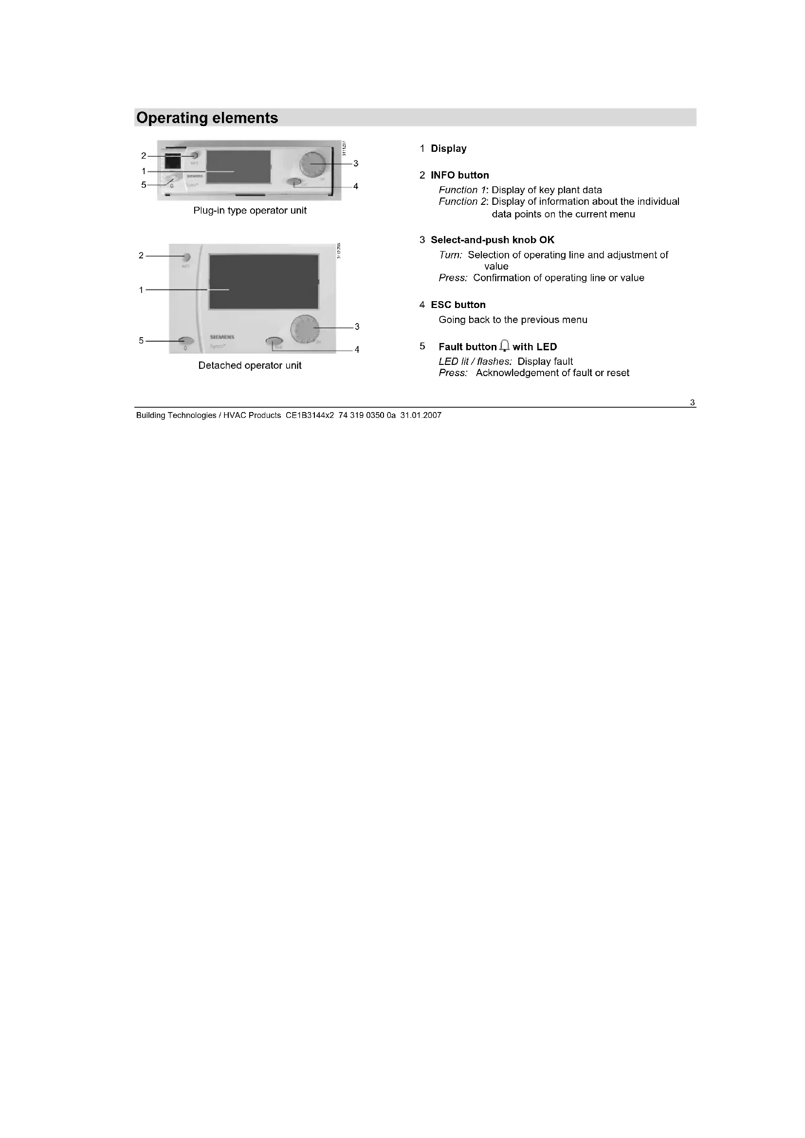
Operating elements
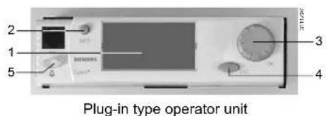
1 Display
2 INFO button
Function 1: Display of key plant data
Function 2: Display of information about the individual data points on the current menu
3 Select-and-push knob OK
Turn:Selection of operating line and adjustment of value Press:Confirmation of operating line or value
4 ESC button
Going back to the previous menu
5 Fault button with LED
LED lit / flashes: Display fault
Press: Acknowledgement of fault or reset
Display
Building Technologies / HVAC Products CE1B3144x2 74 319 0350 0a 31.01.2007
Symbols and characters on the display
| Symbol | Meaning | Symbol | Meaning |
| ○Arc | Virtual operating mode selector (dot indicates the current operating mode). | ■ | Setting level – display and settings |
| ■ | Info level – display of key plant data | ||
| ○ | Room operating mode "Comfort". | ||
| ○ | Room operating mode "Precomfort". | ||
| ○ | Room operating mode "Economy". | ||
| ○ | Protection. | ◎ | Time switch |
| □ | Operation selector (Logic 1) or Logic 1 | ||
| ←1 | Trend 1 | ||
| ○ | Help picture "Explanations relating to the query data point". | □n1 | Meter 1 |
| □1 | Pump 1 | ||
| ○ | Please wait – the controller is working | □1 | Controller 1 |
| ✓ | Value set | Holidays | |
| 248 | Page numbers – current / total | × | Special day |
| Fault |
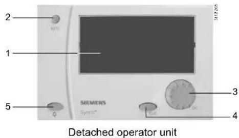
Navigate menu
Start display:
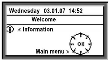
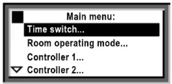
Main menu:
Introduction
These Operating Instructions assist you in operating the controller in all standard situations (Readjust time ... etc., starting on page 9). The Operating Instructions always give you the Path you need to follow through the menu to reach the relevant function - from the start display to the adjustable value.
Start page
When not operated, the display always shows the start display - unless a fault has occurred.
- Press the OK knob: The list of menus appear.
Main menu:
- Turn the OK knob: The cursor advances from one line to the next.
- The selected line appears with a black background and inverse text.
- Select the required option.
- Confirm by pressing the OK knob.
Submenu:
Setting the numerical value:
Submenu
- Now, you are on the submenus.
- The 3 dots (...) after the text indicate that additional submenus follow.
- Follow the indicated path by turning the OK knob to find the line, then push to confirm.
- At the end of the path you will reach the adjustable value.
Setting the numerical value
- The numerical value appears as a pop-up
- Adjust the value by turning the OK knob.
- Then, confirm the value by pressing the OK knob.
- The cursor now advances to the next value to be adjusted, or returns to the data point if there is no other value to be adjusted.
- Press the ESC button to return to the previous entry box or menu.
- When you press the ESC button several times, you will reach the start display again.
With the majority of menus, you can display information about the option currently selected. Press the INFO button.
7
Building Technologies / HVAC Products CE1B3144x2 74 319 0350 0a 31.01.2007
Readjust time or date
Time of day/date
All data of the yearly time switch in your controller were entered when your plant was commissioned. If readjustments are required, use the Time of day / date menu.
Summer and wintertime
The same is true if you need to readjust the dates for the start of summer and wintertime.
Note: Do not enter the actual dates of changeover but, in accordance with international standards, the earliest possible dates for the start of summertime and winter-time!
The menu Time of day/date
The time of day (e.g. 09:53)
The date (e.g. July 25)
The year (e.g. 2007)
The start of daylight savings time (e.g. March 25)
The start of standard time (e.g. October 25)
Path: Welcome > Main menu > Time of day/date... > ...
The change from wintertime to summertime, and vice versa, takes place automatically!
Building Technologies / HVAC Products CE1B3144x2 74 319 0350 0a 31.01.2007
Heat or cool per time switch program
In room operating mode controller operates according to the selected heating program.
Time switch program
In the time switch program, the start time and associated room operating mode have been entered for all periods of 24-hour heating / cooling operation. The heating program has been entered for you; if you wish, you can change the entries made (Page 14) to satisfy your personal needs.
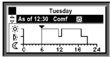
Example of a time program:
As of 6:00 am Comfort mode
As of 11:30 am Precomfort mode
As of 12:30 pm Comfort mode
As of 7:00 pm Precomfort mode
As of 9:00 pm Economy mode
Do not heat or cool per time switch program
Select another room operating mode
If you do not want to heat or cool according to the time switch program (i.e., not automatically), you need to change the preselection for the room operating mode.
Setpoints
The setpoints assigned to the room operating modes use the same symbols and designations.
Setting setpoints is described on pages 12 and 13.
| Symbol | Room operating mode | Comments |
| \( \text{ }_{\text{ }_{\text{ }_{\text{ }_{\text{ }_{\text{ }_{\text{ }_{\text{ }_{\text{ }_{\text{ }_{\text{ }_{\text{ }_{\text{ }_{\text{ }_{\text{ }_{\text{ }_{\text{ }_{\text{ }_{\text{ }_{\text{ }_{\text{ }_{}}}}}}}}}}}}}}}}}} | Comfort Plant ON, Heating / Cooling on comfort | |
| \( \text{ }_{\text{ }_{\text{ }_{\text{ }_{\text{ }_{\text{ }_{\text{ }_{\text{ }_{\text{ }_{\text{ }_{\text{ }_{\text{ }_{\text{ }_{\text{ }_{\text{ }_{\text{ }_{\text{ }_{\text{ }_{\text{ }_{ \text{ }_{\text{ }_{\text{ }_{\text{ }_{\text{ }_{\text{ }_{\text{ }_{\text{ }_{\text{ }_{\text{ }_{\text{ }_{\text{ }_{\text{ }_{\text{ }_{\text{ }_{\text{ }_{\text{ }_{\text{ }_{\text{ }_{\text{ } _ { } _ { } _ { } _ { } _ { } _ { } _ { } _ { } _ { } _ { } _ { } _ { } _ { } _ { } _ { } _ { } _ { } _ { } _ { } _ { } _ { } _ { } _ { } _ { } _ { } _ { } _ { } _ { } _ { } _ { } _ { } _ { } _ { } _ { }\right) \) | Precomfort Plant ON, Heating / Cooling on precomfort | |
| \( \text{ }_{\text{ }_{\text{ }_{\text{ }_{\text{ }_{\text{ }_{\text{ }_{\text{ }_{\text{ }_{\text{ }_{\text{ }_{\text{ }_{\text{ }_{\text{ }_{\text{ }_{\text{ }_{\text{ }_{\text{ }_{\text{ } _ { } _ { }_{\text{ } _ { } _ { } _ { } _ { } _ { } _ { } _ { } _ { } _ { } _ { } _ { } _ { } _ { } _ { } _ { } _ { } _ { } _ { } _ { } _ { } _ { } _ { } _ { } _ { } _ { } _ { } _ { } _ { } _ { } _ { } _ { } ^ { } }} | Economy Plant OFF, Sustained mode Heating / Cooling on economy; Night cooling and frost protection activated | |
| \( \text{ }_{\text{ }_{\text{ }_{\text{ }_{\text{ }_{\text{ }_{\text{ }_{\text{ }_{\text{ }_{\text{ }_{\text{ }_{\text{ }_{\text{ }_{\text{ }_{\text{ }_{\text{ }_{\text{ }_{\text{ }_{\text{ } \( \text{ }_{\text{ }_{\text{ }_{\text{ }_{\text{ }_{\text{ }_{\text{ }_{\text{ }_{\text{ }_{\text{ }_{\text{ }_{\text{ }_{\text{ }_{\text{ }_{\text{ }_{\text{ }_{\text{ }_{\text{ }_{\text{ }_{\text{ } \( \text{ }_{ \text{ }_{\text{ }_{\text{ }_{\text{ }_{\text{ }_{\text{ }_{\text{ }_{\text{ }_{\text{ }_{\text{ }_{\text{ }_{\text{ }_{\text{ }_{\text{ }_{\text{ }_{\text{ }_{\text{ }_{\text{ }_{\text{ }_{ \text{ } _ { } _ { } _ { } _ { } _ { } _ { } _ { } _ { } _ { } _ { } _ { } _ { } _ { } _ { } _ { } _ { } _ { } _ { } _ { } _ { } _ { } _ { } _ { } _ { } _ { } _ { } _ { } _ { } _ { } _ { } _ { } _ { } ^ { } }}}}}}}} | frost protection active |
Path: Welcome > Main menu > Room operating mode... > Preselection > ...
Do not forget to switch back to auto when you only intend to heat/cool temporarily!
10
Building Technologies / HVAC Products CE1B3144x2 74 319 0350 0a 31.01.2007
Operate aggregates per time switch 2
When your controller is configured with a time switch, the controlled aggregate (e.g. a pump) is switched on and off per the set time switch program.
If also configured with [Time switch 2] op selector, it must be set to auto, to automatically switch on and off the aggregate per the set time switch program.
If a [time switch 2] op selector is available and you do not want to control the aggregate per the time switch program, you can manually override it with the [time switch 2] op selector either on or off.
Example of a time program:
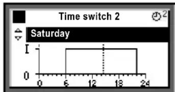
Switched on at 6:00 am - switched off at 10:00 pm
Path: Welcome > Main menu > [Time switch 2] op selector > Preselection:
If you want to set the plant to On or Off for a limited period only, do not forget to return to auto in due time!
11
Room temperature
Your universal controller offers 4 room operating modes. Each room operating mode are assigned two temperature setpoints (heating and cooling).
Depending on the selected room operating mode, your controller switches the setpoints per a time program (page 9) or controls continuously to the setpoint for the selected room operating mode.
The following setpoints are available. The default factory settings represent the recommended setpoints.
You can change the comfort and precomfort setpoints as needed. The economy setpoint cannot be set at the user level.
| Symbol | Setpoint Room operating mode | Impact on the room? | Guide value HeatingCooling |
| \( \text{ }_{\text{ }_{\text{ }_{\text{ }_{\text{ }_{\text{ }_{\text{ }_{\text{ }_{\text{ }_{\text{ }_{\text{ }_{\text{ }_{\text{ }_{\text{ }_{\text{ }_{\text{ }_{\text{ }_{\text{ }_{\text{ }_{\text{ }_{\text{ }_{}}}}}}}}}}}}}}}}}} | Comfort This is the setpoint for the occupied room. Ensuring comfortable conditions | 21 °C 24 °C | |
| \( \text{ }_{\text{ }_{\text{ }_{\text{ }_{\text{ }_{\text{ }_{\text{ }_{\text{ }_{\text{ }_{\text{ }_{\text{ }_{\text{ }_{\text{ }_{\text{ }_{\text{ }_{\text{ }_{\text{ }_{\text{ }_{\text{ }_{ \text{ }_{\text{ }_{\text{ }_{\text{ }_{\text{ }_{\text{ }_{\text{ }_{\text{ }_{\text{ }_{\text{ }_{\text{ }_{\text{ }_{\text{ }_{\text{ }_{\text{ }_{\text{ }_{\text{ }_{\text{ }_{\text{ }_{\text{ } _ { } _ { } _ { } _ { } _ { } _ { } _ { } _ { } _ { } _ { } _ { } _ { } _ { } _ { } _ { } _ { } _ { } _ { } _ { } _ { } _ { } _ { } _ { } _ { } _ { } _ { } _ { } _ { } _ { } _ { } _ { } _ { } _ { } _ { }\ }}}}}} | Precomfort This is the energy saving setpoint for the room to ensure that com- fortable conditions are reached quickly when changing to comfort mode | 19 °C 28 °C | |
| \( \text{ }_{\text{ }_{\text{ }_{\text{ }_{\text{ }_{\text{ }_{\text{ }_{\text{ }_{\text{ }_{\text{ }_{\text{ }_{\text{ }_{\text{ }_{\text{ }_{\text{ }_{\text{ }_{\text{ }_{\text{ }_{\text{ }}}}}}}}}}}}}}}} | Economy Plant OFF. A maximum / minimum temperature is ensured in the room (sustained mode) | 15 °C 30 °C | |
| \( \text{ }_{\text{ }_{\text{ }_{\text{ }_{\text{ }_{\text{ }_{\text{ }_{\text{ }_{\text{ }_{\text{ }_{\text{ }_{\text{ }_{\text{ }_{\text{ }_{\text{ }_{\text{ }_{\text{ }_{\text{ }_{\text{ }}}}}}}}}}}}}}} | Protection Plant OFF. Frost protection active ---- ---- |
Path: Welcome > Main menu > Controller1... > ...
12
Building Technologies / HVAC Products CE1B3144x2 74 319 0350 0a 31.01.2007
Room humidity
If your plant also includes room humidity control, the universal controller allows you to change the humidity setpoint limits in comfort and precomfort room operating modes.
The following setpoints are available.
The default factory settings represent the recommended setpoints.
Your controller changes the setpoints according to a time switch program, or maintains the setpoint of the selected operating mode depending on the room operating mode.
| Symbol | Setpoint | Impact on the room? | Upper setpoint | Lower setpoint |
| \( \text{Comfort} \) | Comfort This is the setpoint for the occupied room. Ensuring comfortable conditions | 60 % 40 % | ||
| \( \text{Precomfort} \) | Precomfort This is the energy saving setpoint for the space to ensure that comfortable conditions will be reached quickly when changing to comfort mode | 80 % 20 % | ||
Path: Welcome > Main menu > Controller 2... > ...
13
Change daily heating / cooling periods
General
In the time switch program, you can set the daily heating and cooling periods to suit your individual needs. Each day can accommodate a maximum of 6 switching points; a room setpoint is assigned to each time period.
In addition to the weekdays (Monday through Sunday), you can program a special day, that is, a special 24-hour heating and cooling program. The special day is activated when you make an entry in Holidays ( page 16).
Changes on the controller are possible only if the controller's time switch defines the program. If an external operator station controls the program, changes can only be made from that station.
Observe the following prior to making entries:
- First enter the start time for the heating/cooling phase and then the room operating mode for the phase.
- The following room operating modes, and are available. Set the corresponding setpoints in menu Controller 1 and Controller 2 (page 12 und 13).
- You can copy any 24-hour heating / cooling program to other days ( page 15).
Change and delete times and setpoints
- Select the required day.
- In the diagram, advance the pointer to the time to be changed.
- Set the desired time.
Delete the time: Reset the time via 00:00 until ---:--- appears. - Select the desired operating mode.
- If required, set additional times and select additional setpoints.
Path: Welcome > Main menu > Time switch... > ...
Enter additional switching points
- Select the desired day.
- In the diagram, advance pointer to the last point in time of the current program.
- Turn the OK knob by one notch; --- appears.
- Set the desired start time.
- Set the desired room operating mode.
Copy a 24-hour heating / cooling program
- Select the day to be copied.
- Turn the OK knob clockwise until Copy to: appears.
- Press the OK knob.
- The menu for the day selection (week sections, individual weekdays, special day) appears.
- Select the desired weekday or week section.
- Copy (press the OK knob).
Create a new 24-hour program
The controller is supplied with a 24-hour program for every day (including special days). This means that you will never have to create a new 24-hour program, but only change an existing program.
Operating voltage off-heating / cooling program lost?
In the event of a power failure, the 24-hour programs entered will be maintained, independent of the duration of the power failure.
First, write down a 7-day schedule for daily switching times and operating modes - this will facilitate entry into the controller!
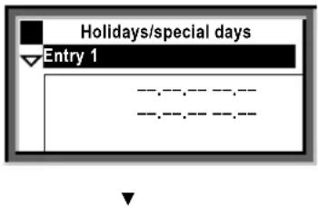
Holiday periods or special days
You can enter a total of 16 holiday periods and special days. During a holiday period, there is no heating / cooling program active, but only the same room operating mode. On special day(s), the special day program is active.
Date
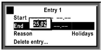
Enter on the submenus Entry 1, Entry 2, Entry 3, etc., the holiday period or special day:
- Operating line start:
Date, year and time of day for the start of holidays or special day. - Operating line end:
Date, year and time of day for the end of holidays or special day. - Operating line reason: Holidays or special day
Every entry can be cancelled:
- Delete entry.
Room operating mode (for holidays).
Enter the desired room operating mode in the operating line room operating mode holidays.
The following choices are available:
Economy or
Protection
The entry will apply to all holiday periods.
Heating / cooling program (for special day)
Enter the heating / cooling program for the special days in Time switch (page 14).
The heating/cooling program applies to all special days.
Path: Welcome > Main menu > Holidays/special days > Entry 1 > ...
Path: Welcome > Main menu > Room operating mode > Room operating mode holidays > ...
Before making entries, prepare a yearly time schedule for all holiday periods!
Display plant operating state
If, during automatic heating / cooling operation, you want to know your plant's current operating state (the room operating mode), go to the info level:
- Go back to the start display by pressing the ESC button.
- Press the INFO button.
The room operating mode is displayed as follows:
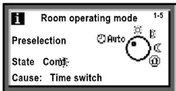
Meanings:
Preselection
The selected room operating mode. In the example shown, the selector is set to Auto
State
This is the current state.
In the example, heating or cooling at the comfort setpoint.
Cause
Here, the reason for the current state is given.
Possible reasons:
- Operating mode contact (manual changeover).
- Operating mode selector.
- Occupancy button on the room unit.
- Timer button on the room unit.
Special day
Holidays - Time switch for the time program (as displayed).
Display current plant data
In addition to plant data on the info pages ( page 17), the submenus configured functions allow you to query additional plant data.
Data queries are explained on page 19 based on the function data acquisition > Trend channel.
You find the following data via the following paths:
Trend.
Main menu > Data acquisition > Trend channel 1...2 >
Display of trend recordings of characteristics.
Meter.
Main menu > Data acquisition > Meter 1...2 >
The meters are used to acquire consumption values.
The current meter reading, the date and the reading of the last 15 months are displayed.
The names of the submenus used in these operating instructions may have been replaced by clear-text names as defined by your service engineer.
18
Building Technologies / HVAC Products CE1B3144x2 74 319 0350 0a 31.01.2007
Display measured value trends
Data acquisition... allows you to display the progression of up to 2 measured values (trend channel...2). This trend function shows measured value trends over the last 8 minutes, the last 8 hours, the last 24 hours or the last 6 days.
Display measured value trend:
-
Select the Data acquisition... menu.
-
Select the required Trend channel 1...2 or the measured value in clear-text; the 24-hour view of the current day appears.
Navigate views:
- Turn the OK knob counter clockwise to jump back the display by 1 day, and vice versa.
- Starting with the current 24-hour view, you reach the view of the last 8 hours by turning the OK knob in clockwise direction. Turn the OK knob clockwise again and you reach the view of the last 8 minutes, turn counter clockwise to return.
- Press the ESC button to go back to the previous menu.
The measured value trend is presented as follows:
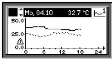
Path: Welcome > Main menu > Data acquisition... > Trend channel 1...2.
Fault
If a fault has occurred in the plant, it will appear on the display and the LED inside the fault button will flash or be lit. Proceed as follows:
LED flashes:
- Press the button to acknowledge the fault.
- If the LED is still lit, the fault still exists or the button must be pressed again to unlock.
LED lit:
- Correct the fault.
- If the LED is still lit, the fault can be unlocked by pressing the button. Unlocking is possible only after the cause of fault has been removed.
Contact your HVAC if the fault is not corrected.
Additional information about the display of faults:
Menu Faults current.
Displays current faults. The following information is displayed about each fault:
Source (e.g. pump 1).
The fault number (for the service engineer).
The date and the time of day the fault occurred.
Fault history...
Displays the last 10 faults. The information given is the same as that provided for current faults.
Fault status message bus.
If your plant includes multiplied networked devices, faults from other controllers are displayed on your controller.
Fault indication on the setting level
Display the current fault by pressing the ESC button for 2 seconds.
Path: Welcome > Main menu > Faults...
Building Technologies / HVAC Products CE1B3144x2 74 319 0350 0a 31.01.2007
Required information for HVAC engineer
Your controller has characteristic data that enable your HVAC engineer to offer support, to answer your questions about the plant, etc. The information is available in the Device information... submenus.
| Operating line | Explanation, example |
| Plant type A01. | |
| Plant type adapted Yes. | |
| File name AEFB01 U3B HQ. | |
| Device type RMU730B-1. | |
| Software version Of the controller. | |
| Hardware version Of the controller. |
Path: Welcome > Main menu > Device information... > Controller... > ...
21
Building Technologies / HVAC Products CE1B3144x2 74 319 0350 0a 31.01.2007
Save energy without sacrificing comfort
During the day, do not allow the room temperature to exceed 21^ when heating. Each additional degree increases heating costs by 6 to 7%
During the day, do not allow the room temperature to fall below 24^ when cooling. Each degree below that level increases the cooling costs
- Guide values for the room temperature in living and working spaces during heating and cooling periods:
- Daytime during heating period: Precomfort = 19 °C, Comfort = 20...22 °C.
Daytime during the cooling period: Precomfort = 28^ , Comfort = 22 24^
Night time during the heating period: Economy = 14...18 °C. Protect objects sensitive to low temperatures, such as plants!
Night time during the cooling period: Economy = 29 31^
-
Ensure that there are no curtains, furniture or other objects in front of or behind air inlets and outlets They have an impact on air circulation and can cause drafts
-
Closed shutters and blinds reduce heat loss
Closing blinds in due time during the cooling season reduces the impact of solar radiation, thus saving cooling costs
Make sure air filters are checked and replaced at regular intervals
If your plant uses a room unit with temperature and humidity sensor, it should not be exposed to thermal and moisture disturbances since these affect the control function. For this reason, the following applies to the reference room where the sensor is located:
- Avoid drafts through open doors
- Avoid heat gains from people, machines and lighting
- Ensure that there are no curtains, furniture or other objects in front of temperature and humidity sensors
Energy savings conserve our natural resources, thus contributing actively to environmental protection!