
AVICZ150BH - GPS Navigation System PIONEER - Free user manual and instructions
Find the device manual for free AVICZ150BH PIONEER in PDF.

| Product type | Multimedia GPS navigation system |
| Brand | Pioneer |
| Model | AVIC-Z150BH |
| Power supply | 12 V DC (vehicle battery) |
| Fuse | 10 A |
| Speaker impedance | 4 Ω to 8 Ω |
| Recommended speaker power | More than 50 W (max output) |
| Connectivity | HDMI, USB, Bluetooth, AV inputs (x2), rear video output, SiriusXM |
| GPS antenna | External (included) |
| Microphone | External (included), adjustable |
| Main functions | GPS navigation, audio/video playback, Bluetooth hands-free calling, smartphone compatibility (iPhone/Android), backup camera, steering wheel controls |
| Backup camera inputs | Yes (RCA, purple/white wire) |
| Safety | Parking brake lock, vehicle speed detection (pink wire), reverse gear detection (purple/white wire) |
| Installation | Double DIN, dashboard or console mounting |
| Dimensions (approx.) | Standard double DIN (178 x 100 x 160 mm) |
| Weight | Approximately 1.5 kg (estimate) |
| Cleaning | Use a soft, dry cloth for the panel. Avoid chemicals. |
| Supplied parts | Navigation unit, GPS antenna, microphone, HDMI cable holder, cables, screws, metal plate |
| Repairability | Professional installation recommended. Spare parts available via authorized Pioneer. |
| Operating temperature | Not specified, but avoid extreme temperatures |
Frequently Asked Questions - AVICZ150BH PIONEER
User questions about AVICZ150BH PIONEER
0 question about this device. Answer the ones you know or ask your own.
Ask a new question about this device
Download the instructions for your GPS Navigation System in PDF format for free! Find your manual AVICZ150BH - PIONEER and take your electronic device back in hand. On this page are published all the documents necessary for the use of your device. AVICZ150BH by PIONEER.
USER MANUAL AVICZ150BH PIONEER
02 Connectingthesystem
Precautionsbeforeconnectingthe system5
Beforeinstallingthisproduct5
Topreventdamage6
-Noticefortheblue/whitelead6
Partssupplied7
InstallingtheHDMI®cableholder7
Connectingthesystem8
WhenconnectingtheiPhone9
WhenconnectingtheAndroid™ device(for AVIC-Z150BHandAVIC-X950BH)11
Connectingthepowercord(1)12
Connectingthepowercord(2)14
Whenconnectingtoseparatelysoldpower amp16
Whenconnectingarearviewcamera18
Whenconnectingtheexternalvideo component19
-UsinganAVinput(AV1)19
-UsinganAVinput(AV2)20
Whenconnectingthereardisplay20
-When using areardisplayconnectedto rearvideooutput20
03 Installation
Precautionsbeforeinstallation21
Toavoidelectromagneticinterference21
Beforeinstalling21
-ForAVIC-Z150BHusers22
Installingthenavigationsystem22
-Installationusingthescrewholeson thesideofthenavigationunit23
-Fasteningthedetachablefaceplate24
InstallingtheGPSantenna25
-Wheninstallingtheantennainsidethe vehicle(onthedashboardorrear shelf)26
Installingthemicrophone27
-Partssupplied27
-Mountingonthesunvisor27
-Installationonthesteeringcolumn28
-Adjustingthemicrophoneangle28
Yournewnavigation systemandthismanual
- Thenavigationfeaturesofthisproduct (andtherearviewcameraoptionifpur-chased)areintendedsolelytoaidyouin theoperationofyourvehicle.Itisnotasub-stituteforyourattentiveness,judgment andcarewhendriving.
- Neverusethisnavigationsystemtoroute tohospitals,policestations,orsimilarfacilitiesinanemergency.Pleasecalltheappropriateemergencynumber.
- Donotoperatethisnavigationsystem(or therearviewcameraoptionifpurchased)if doingsowilldivertyourattentioninany wayfromthesafeoperationofyourvehicle. Alwaysobservesafedrivingrulesandfollowallexistingtrafficregulations.Ifyouexperienceddifficultyinoperatingthesystem orreadingthedisplay,parkyourvehiclein asafelocationandapplytheparkingbrake beforemakingthenecessaryadjustments.
- Thismanualeexplainshowtoinstallthisnavigationsysteminyourvehicle.Operation of thisnavigationsystemisexplainedin theseparatemanualsforthenavigation system.
- Donotinstallthisproductwhereitmay(i) obstructthedriver'svision,(ii)impairthe performanceofanyofthevehicle'soperatingsystemsofsafetyfeatures,including airbags,hazardlampbuttons,or(iii)impair thedriver'sabilitytosafelyoperatethevehicle.Insomecases,itmaynotbepossible toinstallthisproductbecauseofthevehicletypeortheshapeofthevehicleinterior.
Important safeguards
WARNING
Pioneerdoesnotrecommendthatyouinstall yournavigationsystemyourself.Thisproductisdesignedforprofessionalinstallation only.Werecommendthatonlyauthorized Pioneerservicepersonnel,whohavespecial trainingandexperienceinmobileelectronics,setupandinstallthisproduct.NEVER SERVICETHISPRODUCTYOURSELF.Installingorservicingthisproductanditsconnectingcablesmayexposeyoutotheriskof electricshockorotherhazards,andcan causedamagetothenavigationsystemthat isnotcoveredbywarranty.
- Readthismanualfullyandcarefullybefore installingyournavigationsystem.
- Keep this manual handy for future reference.
- Paycloseattentiontoallwarningsinthis manualandfollowtheinstructionscarefully.
- This navigationsystemmayincertaincircumstancesdisplayinaccuratepositionof yourvehicle,thedistanceofobjectsshown onthescreen,andcompassdirections.In addition,thesystemhascertainlimitations,includingtheinabilitytoidentifyone-waystreets,temporarytrafficrestrictions andpotentiallyunsafedrivingareas.Please exerciseyourownjudgmentinthelightof actualdrivingconditions.
- Aswithanyaccessoryinyourvehicle'sinterior,thenavigationsystemshouldnotdivertyourattentionfromthesafeoperation ofyourvehicleasitmayresultinserious injuryordeath.Ifyouexperienceddifficulty inoperatingthesystemorreadingthedisplay,pleasemakeadjustmentswhilesafely parked.
- Pleaseremembertowearyourseatbeltat alltimeswhileoperatingyourvehicle.If youareinanaccident,yourinjuriescanbe considerablymoresevereifyourseatbelt isnotproperlybuckled.
01 (Precautions
- Certaincountryandgovernmentlawsmay prohibitorrestricttheplacementanduse ofthissysteminyourvehicle.Pleasecomplywithallapplicablelawsandregulations regardingtheuse,installationandoperationofyournavigationsystem.
Precautionsbefore connectingthesystem

WARNING
Donottakeanystepstotamperwithordisabletheparkingbrakeinterlocksystem whichisinplaceforyourprotection.Tamperingwithordisablingtheparkingbrakeinterlocksystemcouldresultinseriousinjuryor death.

CAUTION
- If you decide to perform the installation yourself, and have special training and experience in them mobile electronics installations, please carefully follow all of the steps in the installation manual.
- Secureallwiringwithcableclampsorelectricaltape.Donotallowanybarewiringtoremainexposed.
- Donotdirectlyconnecttheyellowleadof thisproducttothevehiclebattery.If the leadisdirectlyconnectedtothebattery, enginevibrationmayeventuallycause theinsulationtofailatthepointwhere thewirepassesfromthepassengercompartmentintotheenginecompartment.If theyellowlead'sinsulationtearsasaresultofcontactwithmetalparts,short-circuitingcanoccur,resultingin considerabledanger.
- Itisextremelydangeroustoallowcables tobecomewoundaroundthesteeringcolumnorshiftlever.Besuretoinstallthis product,itscables,andwiringawayin suchsothattheywillnotobstructorhinderdriving.
- Makesurethatthecablesandwireswill notinterferewithorbecomecaughtin anyofthevehicle'smovingparts,especiallythesteeringwheel,shiftlever,parkingbrake,slidingseattracks,doors,or anyofthevehicle'scontrols.
- Donotroutewireswheretheywillbeexposedtohightemperatures.Iftheinsulationheatsup,wiresmaybecome
damaged, resulting in an short circuit or malfunction and permanent damage to the product.
- DonotcuttheGPSantennacableto shortenitoruseanextensiontomakeit longer. Alteringtheantennacablecould resultinashortcircuitormalfunction.
- Donotshortenanyleads.Ifyoudo,the protectioncircuit(fuseholder,fuseresistororfilter,etc.)mayfailtoworkproperly.
- Neverfeedpowertootherelectronicproductsbycuttingtheinsulationofthepowersupplyleadofthenavigationsystemandtappingintothelead.Thecurrentcapacityoftheleadwillbeexceeded, causingoverheating.
Beforeinstallingthisproduct
- Usethisunitwitha12-voltbatteryandnegativegroundingonly.Failuretodosomay resultinafireormalfunction.
- To avoid shortsin the electrical system, be suretodisconnectthe(-)batterycablebeforeinstallation.
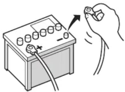
natural_image
Illustration of a hand holding a battery with a switch and power plug, no text or symbols present
Topreventdamage

WARNING
- Usespeakersover50W(outputvalue) andbetween4Ωto8Ω(impedancevalue). Donotuse1Ωto3Ωspeakersforth is unit.
- Theblackcableisground.Wheninstallingthisunitorpoweramp(soldseparately),makesuretoconnecttheground wirefirst.Ensurethatthegroundwireis properlyconnectedtometalpartsofthe car'sbody.Thegroundwireofthepower ampandtheoneofthisunitoranyother devicemustbeconnectedtothecarse separatelywithdifferentscrews.Ifthescrew forthegroundwireloosensorfallsout,it couldresultinfiregenerationofsmokeor malfunction.
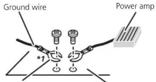
Other devices (Another electronic device in the car)
Metal parts of car's body
*1 Not supplied for this unit.
- Whenreplacingthefuse,besuretoonly useafuseoftheratingprescribedonthis product.
- Whendisconnectingacon connector, pull the connector itself. Donotpullthelead, as youmaypullitoutoftheconnector.
- ThisproductcannotbeinstalledinvehiclewithoutACC(accessory)positionontheignitionswitch.


ACCpositionNoACCposition
• To avoid short-circuiting, cover the disconnected lead with insulating tape. It is especially important to insulate all unused speaker leads, which if left uncovered may
causeashortcircuit.
- Attachtheconnectorsofthesamecolorto thecorrespondingcoloredport,i.e.,blue connectortotheblueport,blacktoblack, etc.
- Refertotheowner'smanualfordetailson connectingthepowerampandotherunits, thenmakeconnectionsaccordingly.
- SinceauniqueBPTLcircuitisemployed, donotdirectlygroundthe⊖sideofthe speakerleaderconnectthe⊖sideofan-othersideofthespeakerleadtogether.Be suretoconnectthe⊖sideofthespeaker leadtothe⊖sideofthespeakerleadon thisnavigationsystem.
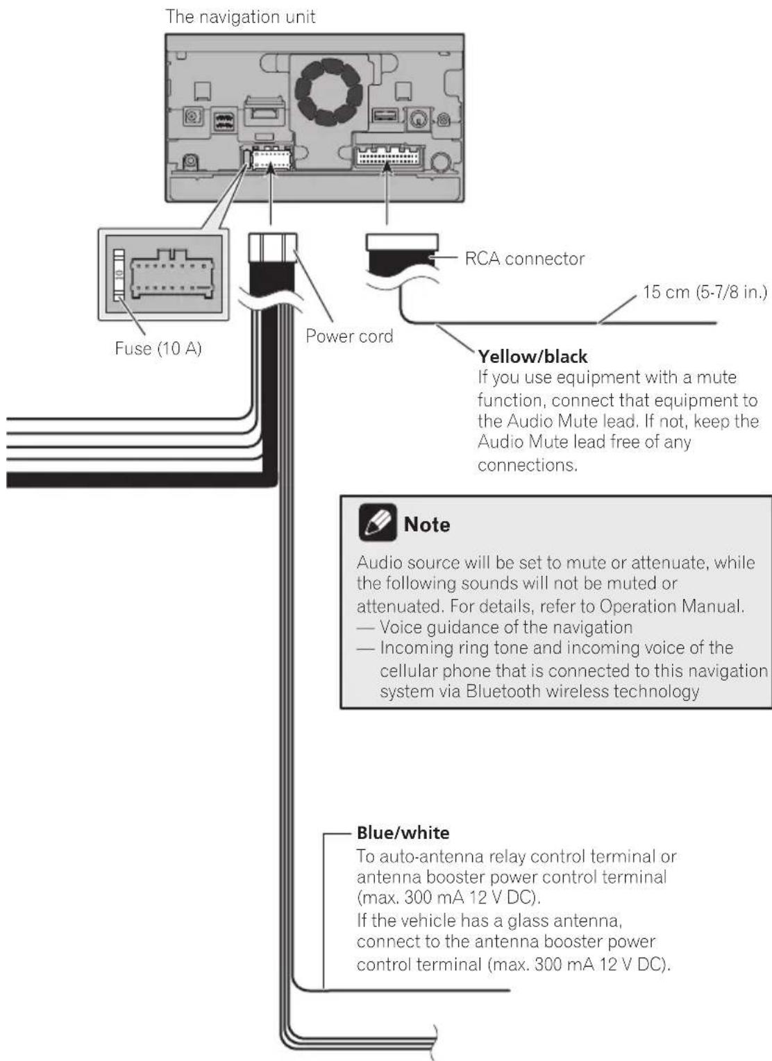
Noticefortheblue/whitelead
- Whentheignitionswitchisturnedon(ACC ON),acontrolsignalisoutputthroughthe blue/whitelead.Connecttoanexternal poweramp'ssystemremotecontrolterminal,theauto-antennarelaycontrolterminal,ortheantennaboosterpowercontrol terminal(max.300mA12VDC).Thecontrolsignalisoutputthroughtheblue/white lead,eveniftheaudiosourceisswitched off.
- Besurenottousethisleadasthepower supplyleadfortheexternalpoweramps. Suchconnectioncouldcauseexcessive currentdrainandmalfunction.
- Besurenottousethisleadasthepower supplyleadfortheauto-antennaorantennabooster.Suchconnectioncouldcause excessivecurrentdrainandmalfunction.

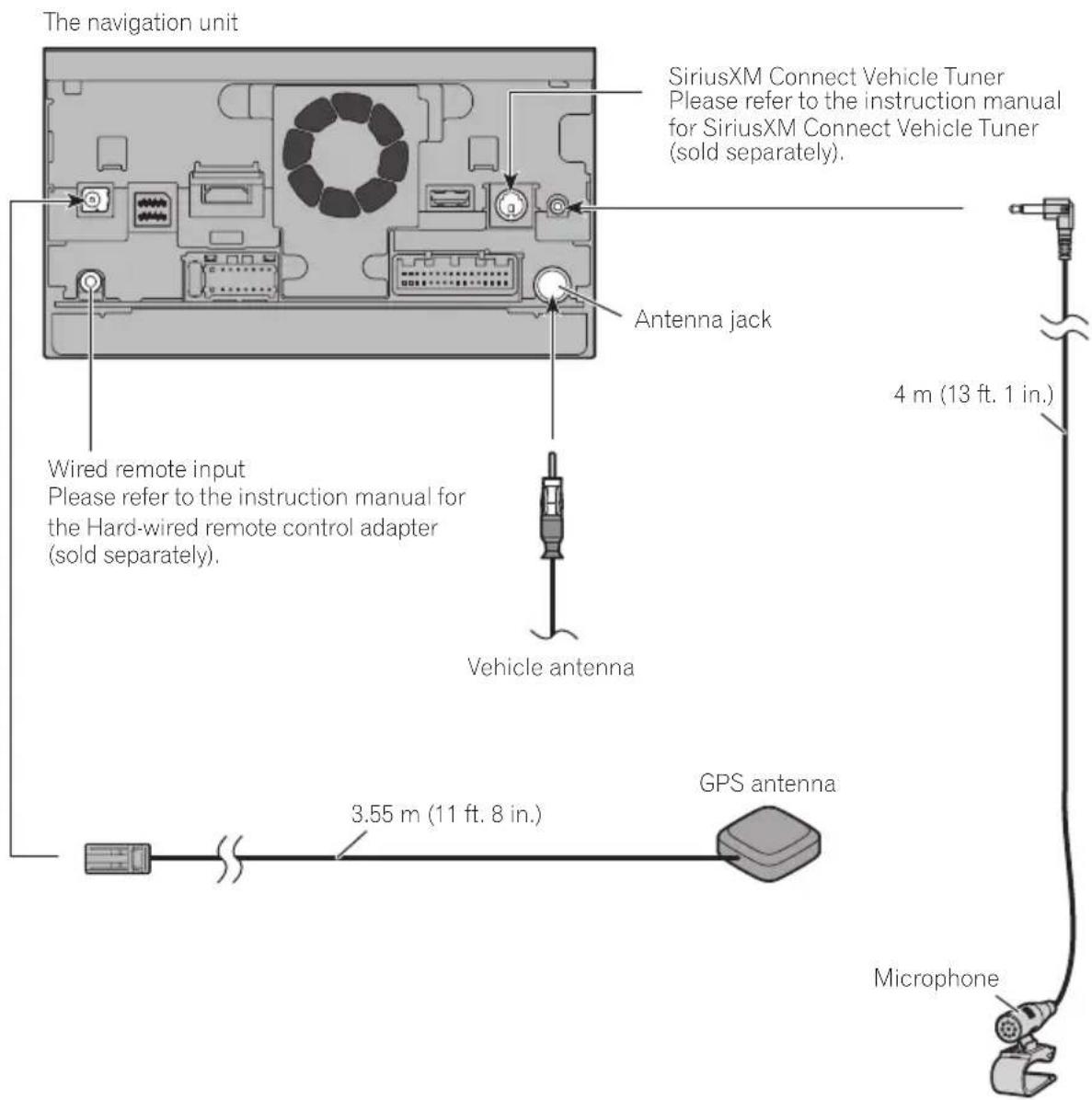
Connectingthesystem
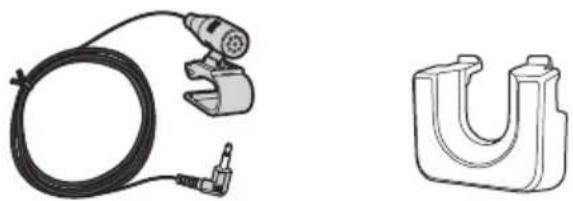
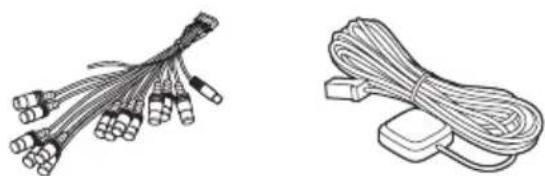
Partssupplied
Partsmarked(*)aresuppliedwithAVIC-Z150BHandAVIC-X950BH.
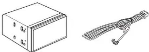
natural_image
Technical line drawing of a rectangular electronic component and a coiled cable with connectors (no text or symbols)ThenavigationunitPowercord
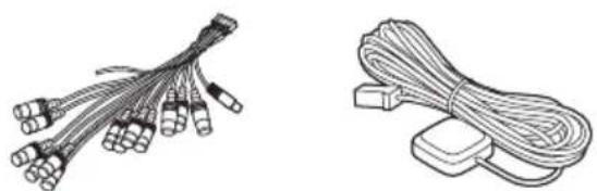
natural_image
Two types of cable connectors shown: a bundle of wires with connectors and a separate coiled cable (no text or symbols)RCAconnectorGPSantenna
natural_image
Technical line drawings of a cable and a U-shaped mechanical component (no text or symbols)MicrophoneHDMlcableholder*
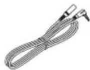
Mini-jackextension cable

InstallingtheHDMI® cable holder
1InsertthelowertaboftheHDMicable holderintothegrooveofthisproduct.
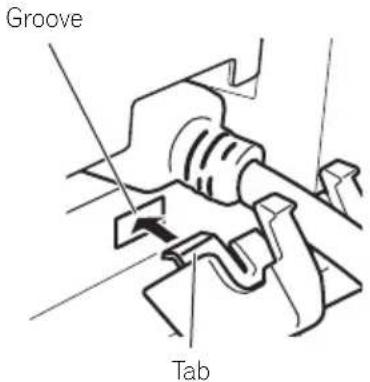
2Insertthetwouppertabsintothethis productbypushingtheHDMIcableholder.
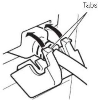
natural_image
Technical line drawing of a mechanical assembly with a labeled 'Tabs' (no other text or symbols)□UsetheHDMIcableholderwhenyouconnectthisproductwiththeseparatelysold AppConnectivityKit(CD-AH200),HDMI/USBinterfacecableforiPod/iPhone(CD-IH202)orVGA/USBinterfacecableforiPod/iPhone(CD-IV202NAVI).
□Nevergriptheholdertightlyoruseforce whenremovingorattaching.
Connectingthesystem

WARNING
- To avoid the risk of accident and the potential violation of applicable laws, this product should never be used while the vehicle is being driven except for navigation purposes. And, also rear displays should not be in a location where it is a visible distraction to the driver.
- In some countries, the viewing of images on a display inside a vehicle even by persons other than the driver may be illegal. Where such regulations apply they must be obeyed and this product's video source should not be used.

WhenconnectingtheiPhone
Connecting an iPhone with Lightning connector (for AVIC-Z150BH and AVIC-X950BH)
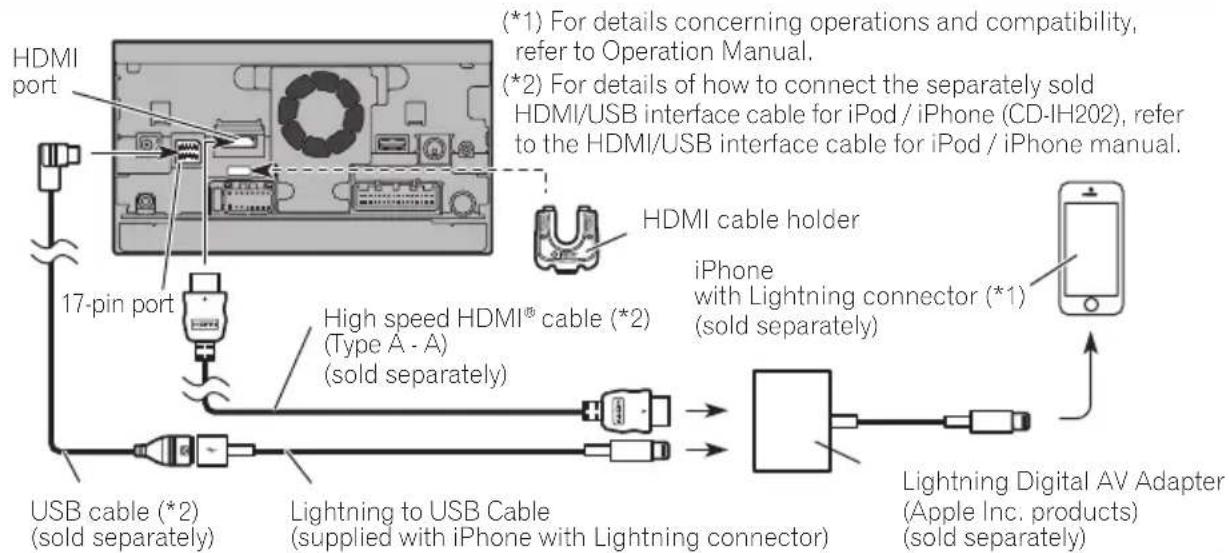

Notes
- When you connect the High Speed HDMI® Cable, use the HDMI cable holder to fix it securely.
- The iPhone needs to be connected to this navigation system via Bluetooth® wireless technology when you want to operate applications on the screen of the navigation system.
Connecting an iPhone with Lightning connector (for AVIC-X850BT and AVIC-X8510BT)
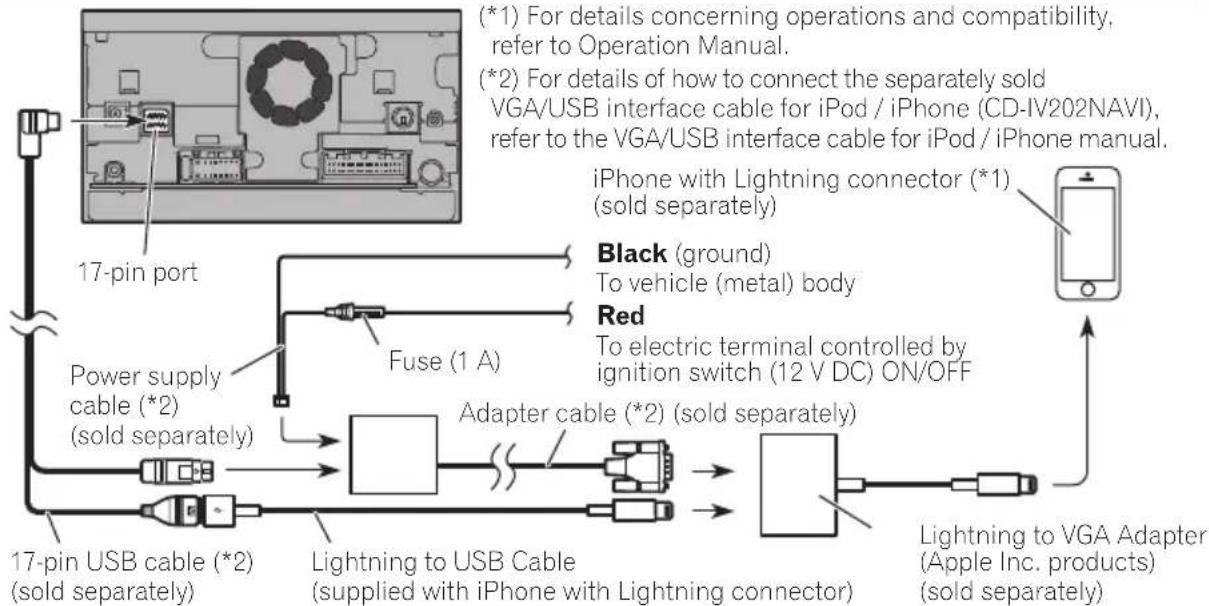
flowchart
graph TD
    A["17-pin port"] --> B["Fuse (1 A)"]
    B --> C["Power supply cable (*2) (sold separately)"]
    C --> D["17-pin USB cable (*2) (sold separately)"]
    D --> E["Lightning to USB Cable (supplied with iPhone with Lightning connector)"]
    E --> F["Adapter cable (*2) (sold separately)"]
    F --> G["Lightning to VGA Adapter (Apple Inc. products) (sold separately)"]
    H["Black (ground)"] --> I["To vehicle (metal) body"]
    J["Red"] --> K["To electric terminal controlled by ignition switch (12 V DC) ON/OFF"]

Note
- The iPhone needs to be connected to this navigation system via Bluetooth® wireless technology when you want to operate applications on the screen of the navigation system.
Connecting an iPhone with 30-pin connector
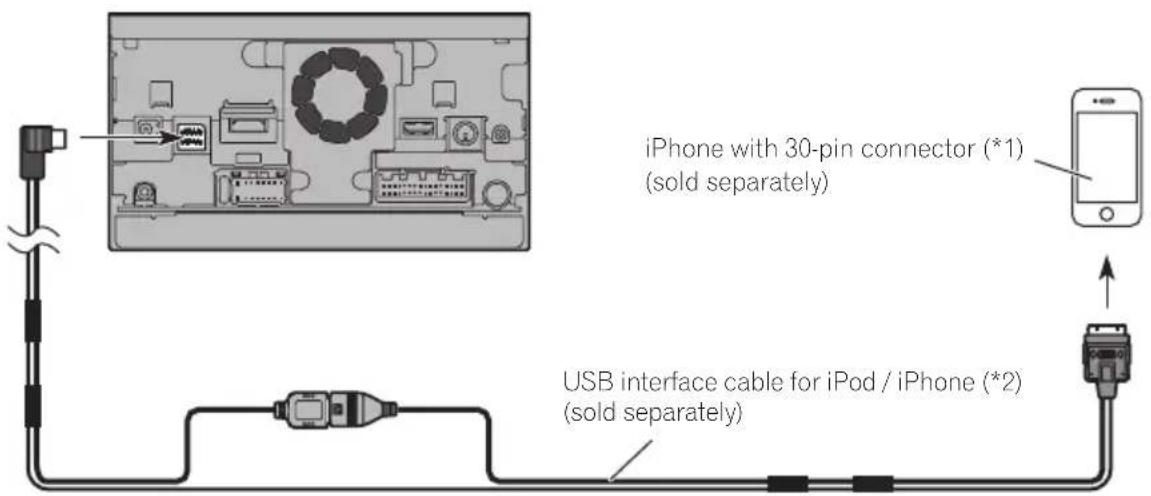
(*1) For details concerning operations and compatibility, refer to Operation Manual.
(*2) For details of how to connect the separately sold USB interface cable for iPod / iPhone (CD-IU201N) refer to the USB interface cable for iPod / iPhone manual.
Connecting an iPhone with a Lightning to 30-pin Adapter
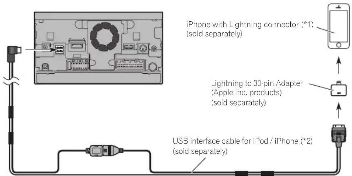
(*1) For details concerning operations and compatibility, refer to Operation Manual.
(*2) For details of how to connect the separately sold USB interface cable for iPod / iPhone (CD-IU201N) refer to the USB interface cable for iPod / iPhone manual.

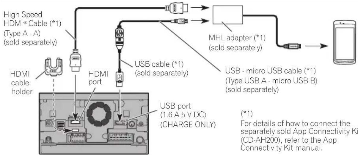
WhenconnectingtheAndroid ^TM device(forAVIC-Z150BH andAVIC-X950BH)
Connecting an Android device with an MHL port
flowchart
graph TD
    A["High Speed HDMI* Cable (*1) (Type A - A) (sold separately)"] --> B["HDMI cable holder"]
    B --> C["HDMI port"]
    C --> D["USB cable (*1) (sold separately)"]
    D --> E["MHL adapter (*1) (sold separately)"]
    E --> F["USB - micro USB cable (*1) (Type USB A - micro USB B) (sold separately)"]
    F --> G["Mobile Device"]
    C --> H["USB port (1.6 A 5 V DC) (CHARGE ONLY)"]
    style A fill:#f9f,stroke:#333
    style G fill:#ccf,stroke:#333

Notes
- When you connect the High Speed HDMI® Cable, use the HDMI cable holder to fix it securely.
- The Android device needs to be connected to this navigation system via Bluetooth® wireless technology when you want to operate applications on the screen of the navigation system.
- An adapter cable will not be used if you use the MHL adapter.
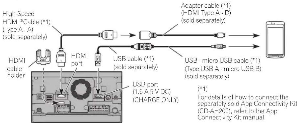
Connecting an Android device with an HDMI port
flowchart
graph LR
    A["High Speed HDMI *Cable (*1) (Type A - A) (sold separately)"] --> B["HDMI cable holder"]
    B --> C["HDMI port"]
    C --> D["USB cable (*1) (sold separately)"]
    D --> E["Adapter cable (*1) (HDMI Type A - D) (sold separately)"]
    E --> F["USB - micro USB cable (*1) (Type USB A - micro USB B) (sold separately)"]
    F --> G["Smartphone"]
    C --> H["USB port (1.6 A 5 V DC) (CHARGE ONLY)"]
    style A fill:#f9f,stroke:#333
    style G fill:#ccf,stroke:#333

Notes
- When you connect the High Speed HDMI® Cable, use the HDMI cable holder to fix it securely.
- The Android device needs to be connected to this navigation system via Bluetooth wireless technology when you want to operate applications on the screen of the navigation system.
- An MHL adapter will not be used if you use the adapter cable.

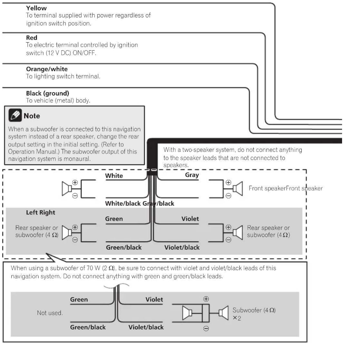
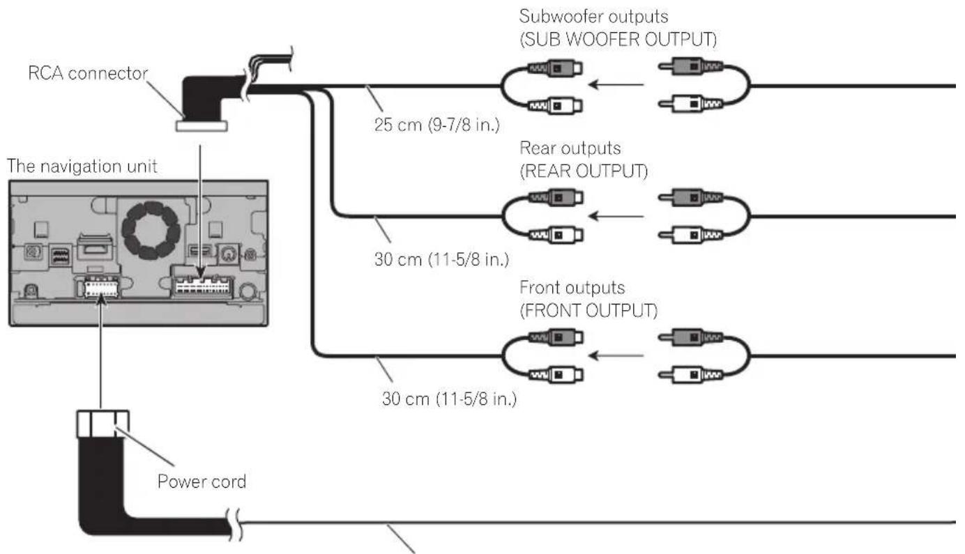
Connectingthepowercord(1)
flowchart
graph TD
    A["Yellow\nTo terminal supplied with power regardless of ignition switch position."] --> B["Red\nTo electric terminal controlled by ignition switch (12 V DC) ON/OFF."]
    B --> C["Orange/white\nTo lighting switch terminal."]
    C --> D["Black (ground)\nTo vehicle (metal) body."]
    D --> E["Note\nWhen a subwoofer is connected to this navigation system instead of a rear speaker, change the rear output setting in the initial setting. (Refer to Operation Manual.) The subwoofer output of this navigation system is monaural."]
    E --> F["Left Right\nRear speaker or subwoofer (4 Ω)"]
    E --> G["Right Right\nGreen/black\nWhite/black\nGray/black\nViolet/black\nViolet"]
    F --> H["Subwoofer (4 Ω) × 2"]
    G --> I["Subwoofer (4 Ω) × 2"]
    H --> J["Not used.\nGreen\nGreen/black\nViolet/Violet/black\nGreen"]
    I --> K["Not used.\nGreen\nGreen/black\nViolet/black\nViolet/black\nGreen"]
    J --> L["Front speaker Front speaker"]
    K --> M["Front speaker Front speaker"]
    L --> N["Front speaker Front speaker"]
    M --> O["Front speaker Front speaker"]
Connectingthesystem

Connectingthepowercord(2)
Pink (CAR SPEED SIGNAL INPUT)
The navigation system is connected here to detect the distance the vehicle travels. Always connect the vehicle's speed detection circuit. Failure to make this connection will increase errors in the vehicle's location display.

WARNING
IMPROPER CONNECTION MAY RESULT IN SERIOUS DAMAGE OR INJURY INCLUDING ELECTRICAL SHOCK, AND INTERFERENCE WITH THE OPERATION OF THE VEHICLE'S ANTILOCK BRAKING SYSTEM, AUTOMATIC TRANSMISSION AND SPEEDOMETER INDICATION.

CAUTION
It is strongly suggested that the speed pulse wire be connected for accuracy of navigation and better performance.

Note
The position of the speed detection circuit and the position of the parking brake switch vary depending on the vehicle model. For details, consult your authorized Pioneer dealer or an installation professional.
Light green (PARKING BRAKE)
Used to detect the ON/OFF status of the parking brake. This lead must be connected to the power supply side of the parking brake switch.
If this connection is made incorrectly or omitted, certain functions of your navigation system will be unusable.

WARNING
LIGHT GREEN LEAD AT POWER CONNECTOR IS DESIGNED TO DETECT PARKED STATUS AND MUST BE CONNECTED TO THE POWER SUPPLY SIDE OF THE PARKING BRAKE SWITCH. IMPROPER CONNECTION OR USE OF THIS LEAD MAY VIOLATE APPLICABLE LAW AND MAY RESULT IN SERIOUS INJURY OR DAMAGE.
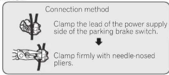
flowchart
graph TD
    A["Connection method"] --> B["Clamp the lead of the power supply side of the parking brake switch."]
    B --> C["Clamp firmly with needle-nosed pliers."]
Connectingthesystem
Violet/white (REVERSE GEAR SIGNAL INPUT)
This is connected so that the navigation system can detect whether the vehicle is moving forwards or backwards. Connect the violet/white lead to the lead whose voltage changes when the shift lever is put in reverse. Unless connected, the sensor may not detect your vehicle traveling forward/backward properly, and thus the position of your vehicle detected by the sensor may be misaligned from the actual position.

Note
When you use a rear view camera, please make sure to connect this lead. Otherwise you cannot switch to the rear view camera picture.

Whenconnectingtoseparatelysoldpoweramp
Blue/white
To system control terminal of the power amp (max. 300 mA 12 V DC).

Notes
- You can change the RCA output of the subwoofer depending on your subwoofer system. (Refer to Operation Manual.)
- The subwoofer output of this navigation system is monaural.
Connectingthesystem
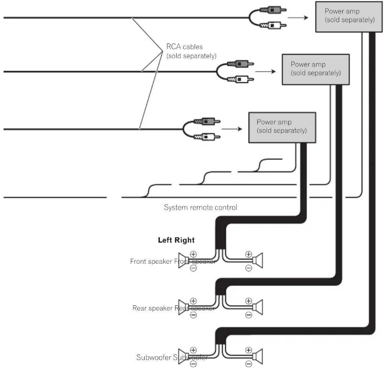
flowchart
graph TD
    A["Input"] --> B["RCA cables (sold separately)"]
    B --> C["Power amp (sold separately)"]
    C --> D["Power amp (sold separately)"]
    D --> E["Output"]
    F["Input"] --> G["Power amp (sold separately)"]
    G --> H["System remote control"]
    H --> I["Left Right"]
    I --> J["Front speaker Front-speaker"]
    I --> K["Rear speaker Rear-speaker"]
    I --> L["Subwoofer Subwoofer"]
    J --> M["+"]
    K --> N["+"]
    L --> O["+"]

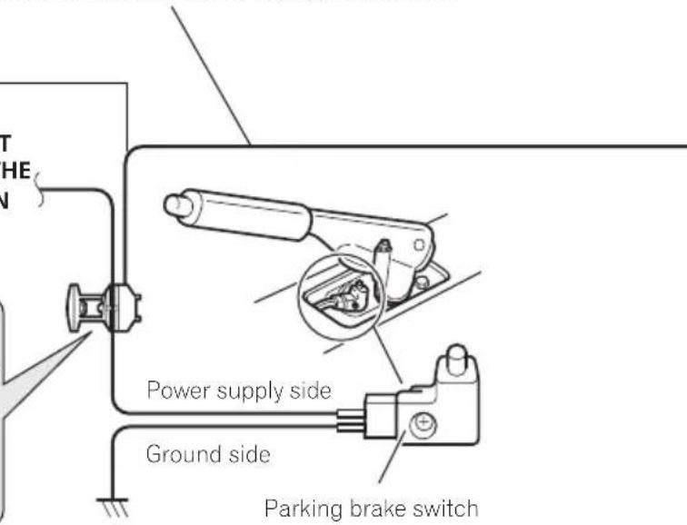
Whenconnectingarear viewcamera
When this product is used with a rear view camera, it is possible to automatically switch from the videotorear view image when the shiftleverismoved to REVERSE(R). Rear Viewmode also allows you to check what is behind you while driving.

WARNING
USEINPUTONLYFORREVERSEORMIRROR IMAGEREARVIEWCAMERA.OTHERUSEMAY RESULTININJURYORDAMAGE.

CAUTION
- Thescreenimagemayappearreversed.
- Therearviewcameraisusedasanaidto keepaneyontrailers,orbackingintoatight parkingspot.Donotusethisfunctionforentertainmentpurposes.
- Objectsinrearviewmayappearcloseror moredistantthaninreality.
- Plesenotethattheimageareashownbythe rearviewcameramaydifferslightlywhenfull-screenimagesaredisplayedwhenbacking andwhencheckingtherearofthevehicle whilemovingforward.
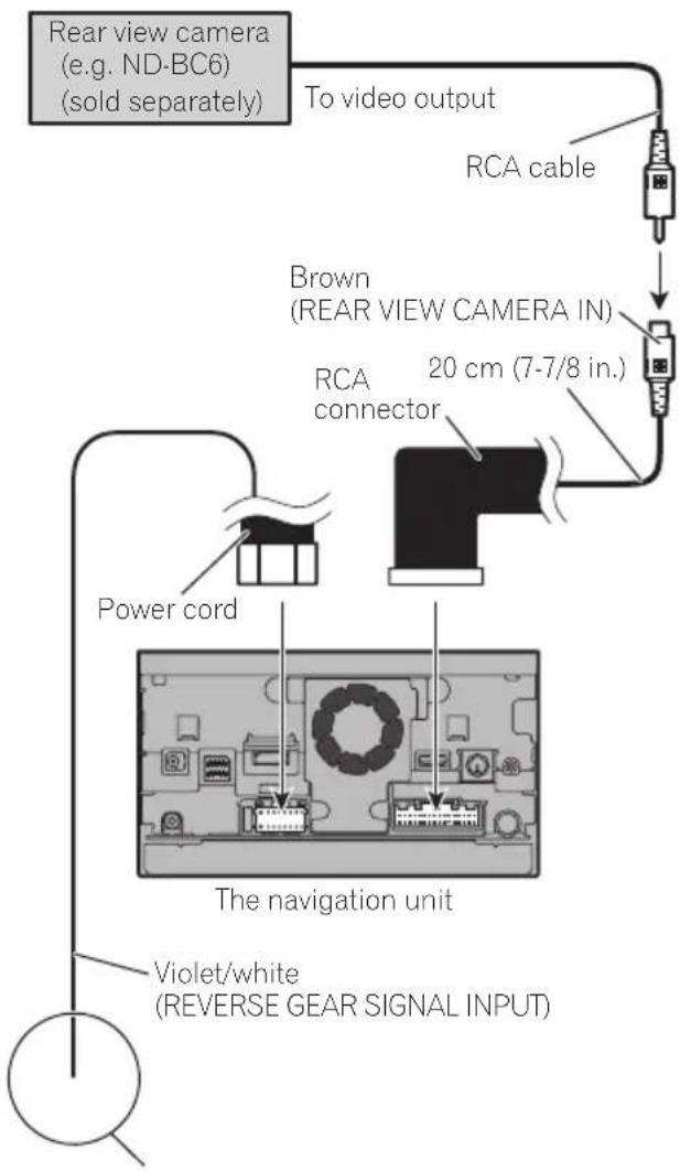
flowchart
graph TD
A["Rear view camera (e.g. ND-BC6) (sold separately)"] --> B["To video output"]
B --> C["RCA cable"]
C --> D["Brown (REAR VIEW CAMERA IN)"]
D --> E["RCA connector"]
E --> F["20 cm (7-7/8 in.)"]
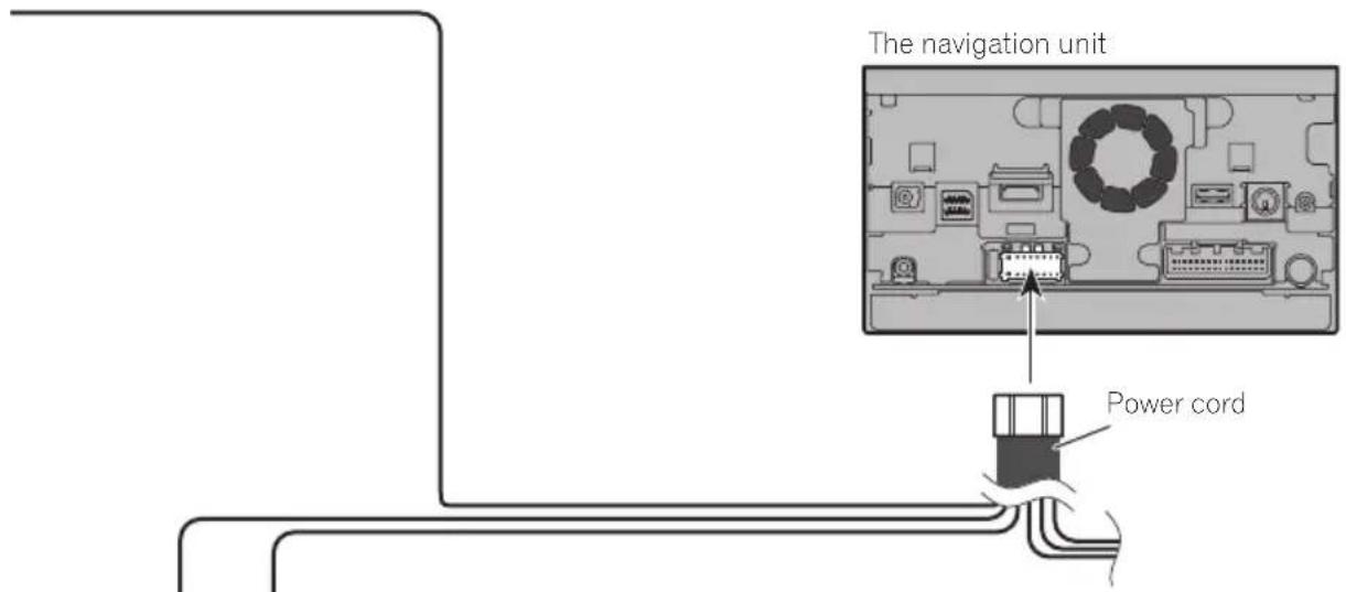
G["Violet/white (REVERSE GEAR SIGNAL INPUT)"] --> H["The navigation unit"]
I["Power cord"] --> J["Image with internal components"]
Formoredetailsaboutthewiring,refertoConnecting thepowercord(2)onpage14.

Notes
- Thismodeisavailablewhentherearview camerasettingissetto"On".(Fordetails, refertoOperationManual.)
- Connectthenavigationsystemtotherear viewcameraonly.Donotconnecttoany otherequipment.

Connectingthesystem
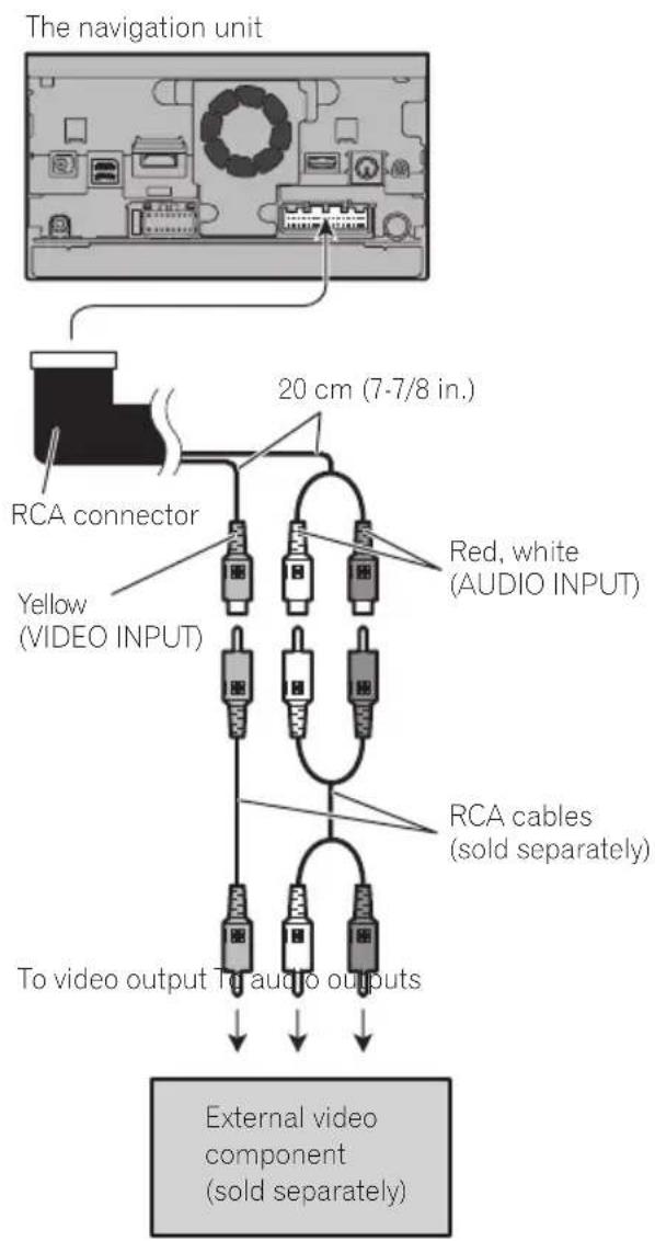
Whenconnectingthe externalvideocomponent UsinganAVinput(AV1)

flowchart
graph TD
    A["The navigation unit"] --> B["RCA connector"]
    B --> C["AUX input"]
    C --> D["Mini-jack extension cable 2 m (6 ft. 7 in.)"]
    D --> E["Mini-jack AV cable (CD-RM10) (sold separately)"]
    E --> F["Red, white"]
    E --> G["Yellow"]
    E --> H["To video output"]
    E --> I["To audio outputs"]
    E --> J["External video component (sold separately)"]
- Thismodeisavailablewhenthesettingof video input 1 (AV1) is set to "On". (For details, refertoOperationManual.)
CAUTION
Besuretouseamini-jackAVcable(CD-RM10) (soldseparately)forwiring.Ifyouuseother cables,thewiringpositionmightdifferresulting indisturbedimagesandsounds.
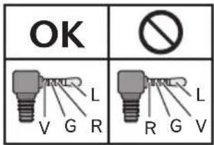
L: Left audio (White)
R : Right audio (Red)
V: Video (Yellow)
G: Ground
UsinganAVinput(AV2)
- Thismodeisavailablewhenthesettingof video input 2 (AV2) is set to "On". (For details, refertoOperationManual.)
Whenconnectingtherear display
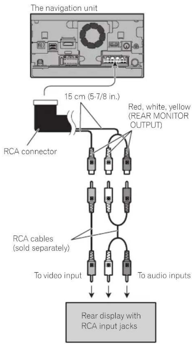
When using areardisplay connected to rear video output
WARNING
NEVERinstallthereardisplayinalocation that enable sthedrivertowatch the video sourcewhiledriving.
Thisnavigationsystem'srearvideooutputisfor connectionofadisplaytoenablepassengersin therearseatstowatchthevideosource.
Precautionsbefore installation

CAUTION
- Neverinstallthisproductinplaceswhere, orinamannerthat:
—Could injurethedriverorpassengersif thevehiclestopssuddenly.
—Mayinterferewiththedriver'soperationofthevehicle,suchasonthefloorinfrontofthedriver'sseat,orclosetothesteeringwheelorshiftlever. - Makesurethereisnothingbehindthe dashboardorpanelingwhendrillingholes inthem.Becarefulnottodamagefuel lines,brakelines,electroniccomponents, communicationwiresorpowercables.
- Whenusingscrews, donotallowthemto comeintocontactwithanyelectricallead. Vibrationmaydamagewiresorinsulation, leadingtoashortcircuitorotherdamage tothevehicle.
- Toensureproperinstallation,besureto usethesuppliedpartsinthemannerspecified.Ifanypartsarenotsuppliedwith thisproduct,usecompatiblepartsinthe mannersspecifiedafteryouhavetheparts' compatibilitycheckedbyyourdealer.If partsotherthansuppliedorcompatible onesareused,theymaydamageinternal partsofthisproductortheymaywork looseandtheproductmaybecomedetached.
- Itisextremelydangeroustoallowcables tobecomewoundaroundthesteeringcolumnorshiftlever.Besuretoinstallthis product,itscables,andwiringawayin suchsothattheywillnotobstructorhinderdriving.
- Makesurethatleadscannotgetcaughtin adoorortheslidingmechanismofaseat, resultinginashortcircuit.
-
Please confirm the proper function of your vehicle's other equipment after installation of thenavigations system.
-
Donotinstallthisnavigationsystem whereitmay(i)obstructthedriver'svision,(ii)impairtheperformanceofanyof thevehicle'soperatingsystemsorsafety features,includingairbags,hazardlamp buttonson(iii)impairthedriver'sability tosafelyoperatethevehicle.
- Installthenavigationsystembetweenthe driver'sseatandfrontpassengerseatso thatitwillnotbehitbythedriverorpassengerifthevehiclestopsquickly.
- Neverinstallthenavigationsystemin frontofornexttotheplaceinthedashboard,door,orpillarfromwhichoneof yourvehicle'sairbagswoulddeploy. Pleaserefertoyourvehicle'sowner's manualforreferencetothedeployment areaofthefrontalairbags.
- Failuretofollowalloftheseprecautions mayresultinserious injuryordeath.
Toavoidelectromagnetic interference
Inordertopreventinterference,setthefollowingitemsasfaraspossiblefromthisnavigationsystem,othercablesorleads:
• FM, AMantennaanditslead
- GPSantennaanditslead Inaddition,youshouldlayorrouteeachantennaleadasfaraspossiblefromotherantennaleads.Donotbind,layorrouetethem together,orcrossthem.Electromagnetic noisewillincreasethepotentialforerrorsin thevehicle'slocationdisplay.
Beforeinstalling
- Consultwithyournearestdealerifinstallationrequiresdrillingholesorothermodificationsofthevehicle.
- Beforemakingafinalinstallationofthis product, temporarilyconnectthewiringto confirmthattheconnectionsarecorrect andthesystemworksproperly.
ForAVIC-Z150BHusers
DonotinstallthisnavigationsysteminapositionwheretheopeningoftheLCDpanelisobstructedbyanyobstacles,suchastheshift lever.Beforeinstallingthisnavigationsystem, besuretoleavesufficientspacesothatthe LCDpaneldoesnotobstructtheshiftlever whenitisfullyopened.Thismaycauseinterferencewiththeshiftlever,oramalfunctionof themechanismofthisnavigationsystem.
Installingthenavigation system
Installationnotes
- Donotinstallthenavigationsystemin placesubjecttohightemperaturesorhumidity,suchas:
—Placesclosetoaheater,ventorairconditioner.
—Placesexposedtodirectsunlight,such asontopofthedashboard.
—Placesthatmaybeexposedtorain, suchasclosetothedoororonthevehicle'sfloor.
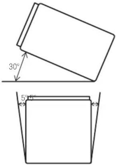
• Install this navigationsysteminan area strongenoughtobearitsweight.Choosea positionwherethis navigationsystemcan befirmlyinstalled,andinstallitsecurely.If this navigation system is not securely installed,the current location of the vehicle cannot be displayed correctly.
- Installthenavigationunithorizontallyona surfacewithin0to30degreestolerance (within5degreestotheleftorright).Improperinstallationoftheunitwiththesurface tiltedmorethanthesetolerancesincreases thepotentialforerrorsinthevehicle'slocationdisplay,andmightotherwisecausereduceddisplayperformance.
- Wheninstalling,toensureproperheatdispersalwhenusingthisunit,makesureyou leaveamplespacebehindtherearpanel andwrapanyloosecablessotheyarenot blockingthevents.

Installation
- Thecordsmustnotcovertheareashown inthefigurebelow. This is necessary to allow the amps and navigation mechanism to dissipate heat.
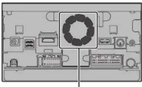
natural_image
Top-down schematic of a computer monitor with integrated circuitry and display panels (no text or labels)Donotcoverthisarea.
- These semiconductor laser will be damaged if to overheats, sodon't install then navigation unit any where hot—for instance, near a heater outlet.
Partssupplied
Partsmarked(*)aresuppliedwithAVIC-X950BH,AVIC-X850BTandAVIC-X8510BT.
natural_image
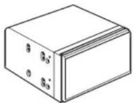
Isometric view of a rectangular block with four small circular holes on its surface (no text or symbols)
ThenavigationunitTrussheadscrew
(5mm×8mm) (6pcs.)
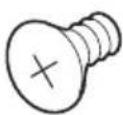

Flushsurfacescrew (5mm×9mm) (6pcs.)
Screw ^* (2mm×4mm) (1pc.)
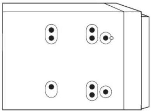
Installationusingthescrewholes onthesideofthenavigationunit
●Fasteningthenavigationunittothe factoryradio-mountingbracket.
Positionthenavigationunitsothatthebracketsscrewholesanditsscrewholesare aligned,andtightenthescrewsatthreelocationsoneachside.
Use either the truss head screw (5mm × 8mm) or flush surfaces screw (5mm × 9mm), depending on the shape of the bracket's screw holes.
natural_image
Simple line drawing of a 3D box with four circular buttons and one small circle on top (no text or symbols)If the pawl interferes with installation, you may bend it down out of the way.
Factory radio-mounting bracket
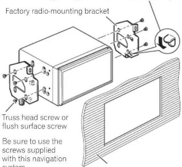
Dashboard or console
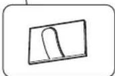
Fasteningthedetachablefaceplate
ThisdescriptionisforAVIC-X950BH,AVIC-X850BTandAVIC-X8510BT. If you donot plantoremovethedetachablefaceplate, the detachablefaceplate can be fastened with the supplied screw.
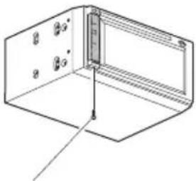
natural_image
Isometric line drawing of a 3D rectangular enclosure with internal components and a vertical scale bar (no text or symbols)Screw(2mm×4mm)

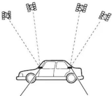
InstallingtheGPSantenna
CAUTION
DonotcuttheGPSantennaleadtoshortenitoruseanextensiontomakeitlonger. Alteringtheantennacablecouldresultinashortcircuitormalfunctionandpermanentdamagetothenavigationsystem.
Installationnotes
- Theantennashouldbeinstalledonalevel surfacewhereradiowaveswillbeblocked aslittleaspossible.Radiowavescannotbe receivedbytheantennaifreceptionfrom thesatelliteisblocked.
natural_image
Diagram of a car with multiple sensor arrays radiating from a central vehicle (no text or symbols present)DashboardRearshelf
- WheninstallingtheGPSantennainside thevehicle,besuretousethemetalsheet providedwithyoursystem.Ifthisisnot used,thereptionsensitivitywillbepoor.
- Donotcuttheaccessorymetalsheet. This would reduce cethesensitivity of the GPS antenna.
• Takecarenottopulltheantennaleadwhen removingtheGPSantenna. Themagnetattachedtotheantennaisverypowerful, and theleadmaybecomedetached. - DonotpainttheGPSantenna, asthismay affect its performance.
Partssupplied
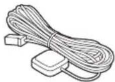
GPSantennaMetalsheet

Wheninstallingtheantennainsidethevehicle(onthedashboard orrearshelf)

WARNING
DonotinstalltheGPSantennaoveranysensorsorventsonthedashboardofthevehicle, asdoingsomayinterferewiththeproper functioningofsuchsensorsorventsandmay compromisetheabilityofthemetalsheet undertheGPSantennatoproperlyandsecurelyaffixtothedashboard.
Affixthemetalsheetonthesurfaceaslevelas possiblewheretheGPSantennafacesthe window.PlacetheGPSantennaonthemetal sheet.(TheGPSantennaisfastenedwithits magnet.)
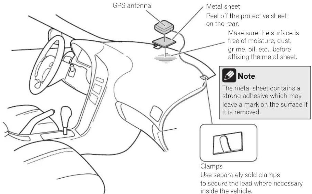
Clamps
Use separately sold clamps to secure the lead where necessary inside the vehicle.


Notes
- Whenattachingthemetalsheet, donotcut itintosmallpieces.
- Somemodelsusewindowglassthatdoes notallowsignalsfromGPSsatellitesto passthrough.Onsuchmodels,installthe GPSantennaontheoutsideofthevehicle.
Installation
Installingthemicrophone
• Install themicrophone in a place where its direction and distance from the driver make it easiest to pickup the driver's voice.
- Makesuretoconnectthemicrophoneto thenavigationsystemafterthesystemis turnedoff(ACCOFF).
Partssupplied
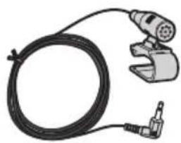
natural_image
Illustration of a welding torch and wire with a clamp (no text or symbols)
MicrophoneDouble-sidedtape
Mountingonthesunvisor
1Fitthemicrophoneleadintothe groove.
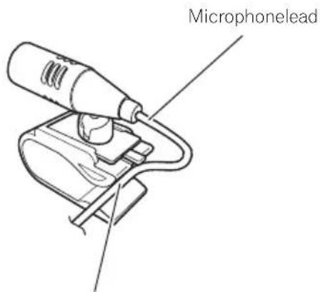
Groove
2Attachthemicrophonecliptothesun visor.
Clamps
Useseparatelysoldclamps
tosecuretheleadwherene-
cessaryinsidethevehicle.
Install themicrophone on the sunvisor when it is in the up position. It cannot recognize the driver's voice if the sunvisor is in the down position.
Installationonthesteeringcolumn
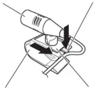
1 Detachthemicrophonebasefrom the microphoneclipbyslidingthemicrophone basewhilepressingthetab.
MicrophoneTab
natural_image
Diagram of a handheld device with directional arrows indicating movement or force (no text or symbols)MicrophoneclipMicrophonebase
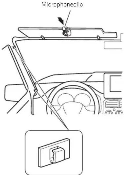
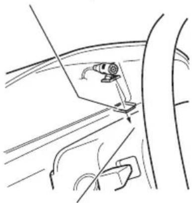
2Mountthemicrophoneonthesteering column.
Double-sidedtape
natural_image
Line drawing of a car's side panel with a clip and handle, no text or symbols presentInstall themicrophone on the steering column, keeping it away from the steering wheel.

natural_image
Line drawing of a car interior showing steering wheel and dashboard, with a close-up inset of the dashboard switch (no text or symbols)Clamps
Useseparatelysold clampstosecurethe leadwherenecessary insidethevehicle.
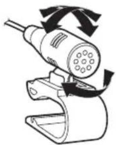
Adjustingthemicrophoneangle
Themicrophoneanglecanbeadjusted.
natural_image
Diagram of a handheld device with rotating arrows indicating motion (no text or symbols)
01 Précautions
Votrenouveausystèmedenavigationetce manuel30
natural_image
Illustration of a hand holding a battery with a power plug, showing terminal connections and polarity (no text or symbols)
natural_image
Technical line drawing of a rectangular component with three small holes and a coiled cable with connectors (no text or symbols)UnitédenavigationCordond'alimentation
natural_image
Two types of cable connectors shown: a bundle of wires and a separate cable with a plug (no text or symbols)natural_image
Technical illustration of a mechanical clamp and a U-shaped bracket component (no text or symbols)HDMI*
natural_image
Top-down schematic of a computer monitor with labeled ports and a circular button (no text or symbols)natural_image
Isometric line drawing of a rectangular block with four labeled faces (no text or symbols)
natural_image
Simple line drawing of a 3D box with four circular buttons and one small circle on top (no text or symbols)natural_image
Isometric line drawing of a 3D rectangular enclosure with internal components and a vertical scale bar (no text or symbols)Vis(2mm×4mm)

Installationdel'antenneGPS

ATTENTION
natural_image
Diagram of a car with multiple sensor arrays radiating from a central vehicle (no text or symbols present)natural_image
Illustration of a coiled cable and two rectangular components (no text or symbols)Installationdumicrophone
natural_image
Illustration of a handheld tool with a coiled cable and connector (no text or symbols)
MicrophoneBandeadhésiveà
doubleface
Installationsurlepare-soleil
natural_image
Line drawing of a handheld tool with a cylindrical component and attached circuit board (no text or symbols)Fente
2Fixezl'agrafepourmicroaupare-soleil.
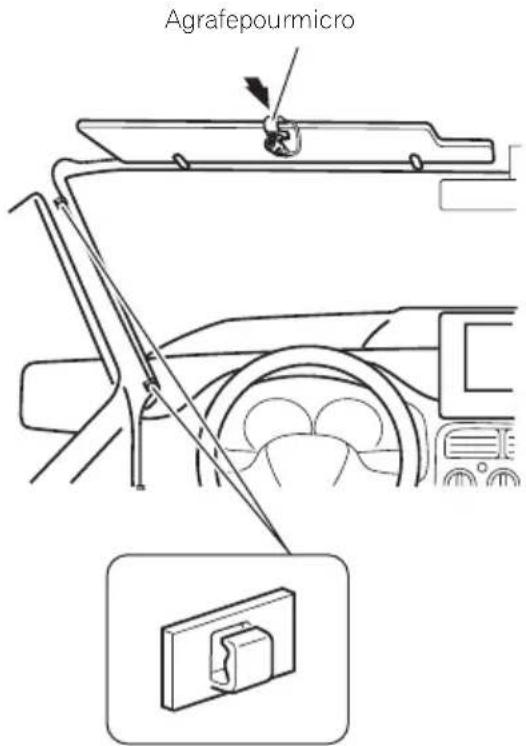
natural_image
Diagram of a handheld device with directional arrows indicating movement or force (no text or symbols)AgrafepourmicroBasedumicrophone
2Montezlemicrophonesurlacolonne dedirection.
Bandeadhésiveàdoubleface

natural_image
Line drawing of a car's side panel showing a clip and handle (no text or symbols)Installezlemicrophonesurlacolonnededirection,àdistancedu volant.
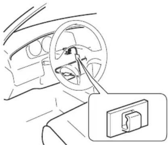
natural_image
Line drawing of a car interior showing steering wheel and dashboard, with a magnified inset showing a switch mechanism (no text or symbols)Serre-fils
natural_image
Diagram of a handheld device with rotating arrows indicating motion (no text or symbols)

PIONEERCORPORATION
1-1, Shin-ogura, Saiwai-ku, Kawasaki-shi,
Kanagawa212-0031, JAPAN
PIONEERELECTRONICS(USA)INC.
P.O.Box1540, Long Beach, California 90801-1540, U.S.A.
TEL:(800)421-1404
PIONEERELECTRONICSOFCANADA, INC.
340FerrierStreet, Unit2, Markham, Ontario L3R2Z5, Canada
TEL:1-877-283-5901
TEL:905-479-4411
PIONEEREUROPENV
Haven1087, Keetberglaan1, B-9120Melsele, Belgium/Belgique
TEL:(0)3/570.05.11
PIONEERELECTRONICSASIACENTREPTE.LTD.
253AlexandraRoad,#04-01,Singapore159936
TEL:65-6472-7555
PIONEERELECTRONICSAUSTRALIAPTY.LTD.
5ArcoLane,Heatherton,Victoria,3202,Australia
TEL:(03)9586-6300
PIONEERELECTRONICSDEMEXICO,S.A.deC.V.
Blvd.ManuelAvilaCamacho13810piso
Col.LomasdeChapultepec,Mexico,D.F.11000
TEL:55-9178-4270
先鋒股份有限公司
台北市內湖區瑞光路407號8樓
電話:886-(0)2-2657-3588
先鋒電子(香港)有限公司
香港九龍長沙灣道909號5樓
電話:852-2848-6488
©2013PIONEERCORPORATION.
Allrightsreserved.
©2013PIONEERCORPORATION.
Tousdroitsdereproductionetde
traductionréservés.

- Connectingthesystem
- Installation
- Yournewnavigation systemandthismanual
- Important safeguards
- WARNING
- (Precautions
- Precautionsbefore connectingthesystem
- CAUTION
- Beforeinstallingthisproduct
- Topreventdamage
- Noticefortheblue/whitelead
- Connectingthesystem
- Partssupplied
- InstallingtheHDMI® cable holder
- WhenconnectingtheiPhone
- Notes
- Note
- Connecting an iPhone with 30-pin connector
- Connecting an iPhone with a Lightning to 30-pin Adapter
- WhenconnectingtheAndroid TM device(forAVIC-Z150BH andAVIC-X950BH)
- Connectingthepowercord(1)
- Connectingthepowercord(2)
- Pink (CAR SPEED SIGNAL INPUT)
- Light green (PARKING BRAKE)
- Violet/white (REVERSE GEAR SIGNAL INPUT)
- Blue/white
- Whenconnectingarear viewcamera
- Whenconnectingthe externalvideocomponent UsinganAVinput(AV1)
- When using areardisplay connected to rear video output
- Precautionsbefore installation
- Toavoidelectromagnetic interference
- Beforeinstalling
- ForAVIC-Z150BHusers
- Installingthenavigation system
- Installationnotes
- Installation
- Installationusingthescrewholes onthesideofthenavigationunit
- ●Fasteningthenavigationunittothe factoryradio-mountingbracket.
- Fasteningthedetachablefaceplate
- InstallingtheGPSantenna
- Wheninstallingtheantennainsidethevehicle(onthedashboard orrearshelf)
- Installingthemicrophone
- Mountingonthesunvisor
- 2Attachthemicrophonecliptothesun visor.
- Installationonthesteeringcolumn
- Adjustingthemicrophoneangle
- Précautions
- Installationdel'antenneGPS
- ATTENTION
- Installationdumicrophone
- Installationsurlepare-soleil
- 2Montezlemicrophonesurlacolonne dedirection.
- PIONEERCORPORATION
Brand : PIONEER
Model : AVICZ150BH
Category : GPS Navigation System