
PAC F400 - Air Conditioning DELONGHI - Free user manual and instructions
Find the device manual for free PAC F400 DELONGHI in PDF.
| Product type | Portable split air conditioner (monoblock with outdoor unit) |
| Brand | De'Longhi |
| Model | PAC F400 |
| Category | Air conditioning |
| Max. power consumption in cooling mode | See rating plate |
| Supply voltage | See rating plate |
| Indoor unit dimensions (W x H x D) | 452 x 800 x 415 mm |
| Indoor unit weight | 35 kg |
| Outdoor unit dimensions (W x H x D) | 570 x 475 x 260 mm |
| Outdoor unit weight | 18 kg |
| Max. treated air volume | 460 m³/h |
| Fan speeds | 2 |
| Main functions | Cooling, fan/air purification |
| Filter type | Washable antibacterial filter + FILTRETE™ electrostatic filter |
| Programmable timer | Yes, 24-hour programming in 15-minute intervals |
| Connection | Duct with quick connectors (detachable) |
| Installation | Indoor unit on floor (min. 30 cm from walls); outdoor unit on terrace or wall |
| Safety | Grounding mandatory, do not use extension cord, unplug before maintenance |
| Maintenance | Clean antibacterial filter weekly; replace FILTRETE filter at end of season |
| Condensation management | Automatic evaporation drainage; backup tank with indicator light |
| Recommended operating temperature | Room: 21–32°C; outdoor: 21–43°C |
| Repairability | Contact an authorized after-sales service center |
Frequently Asked Questions - PAC F400 DELONGHI
User questions about PAC F400 DELONGHI
0 question about this device. Answer the ones you know or ask your own.
Ask a new question about this device
Download the instructions for your Air Conditioning in PDF format for free! Find your manual PAC F400 - DELONGHI and take your electronic device back in hand. On this page are published all the documents necessary for the use of your device. PAC F400 by DELONGHI.
USER MANUAL PAC F400 DELONGHI
natural_image
Abstract sketch of horizontal lines with a small circular symbol at the center (no text or symbols)
entile Cliente,
Thank you for having purchased an appliance made by De' Longhi, the international leader in portable air conditioning units. Thanks to our years of experience all around the world we are constantly improving the quality and performance of Pinguino. We are confident that you will be satisfied with your purchase and enjoy the cool comfort created by the Pinguino for many years to come. You should spend some time reading this instruction manual and keep it handy to refer to in order to use your Pinguino in conditions of maximum efficiency and peace of mind.

hère Cliente, Cher Client,
natural_image
Line drawing of a portable air conditioner unit on a hallway, with a dimension label indicating 20mm (no text or symbols present)UTILIZZO DEI RACCORDI RAPIDI
(solo mod. F400 e F300)
natural_image
Line drawing of hands using a tool to lift a cylindrical component (no text or symbols)natural_image
Illustration of hands performing a mechanical valve or actuator operation (no text or symbols present)natural_image
Line drawing of a kitchen interior with a suitcase and ladder (no text or symbols)TIMER: REGOLAZIONE DELL'ORA
natural_image
Line drawing of a window with curtains and sheer curtains, no text or symbols presentPROBLEMI CAUSE RIMEDI
What is Pinguino Pinguino and SuperPinguino
During the summer, optimum comfort is achieved with a temperature of between 24 and 27^ and about 50% relative humidity.
An air conditioner removes moisture and heat from the room where it is located. One advantage of portable air conditioning units over fitted models is that they can be moved from one room to another in the home or even transferred between different buildings.
The hot air in your room is passed through a coil cooled by refrigerant gas, losing excess heat and moisture before being discharged again into the room.
In single unit models (Pinguino), a small part of this air is used to cool the refrigerant gas before, hot and moist, being discharged outside.
In suitcase models (Super-Pinguino), the circuit is cooled using the air outside.
Each Pinguino and Super-Pinguino can also be used as a fan only.
For more details, contact or visit our Internet site
www.delonghi.it
Important Safe-guards
- This appliance has been manufactured to cool and de-humidify domestic environments and should not be used for other purposes.
- It is dangerous to alter or modify the unit's characteristics in any way.
- The appliance must be installed in conformity with the relevant national legislation.
- Should repairs be necessary, contact the nearest authorised Repair Service Centre. Unauthorised servicing can be dangerous.
- This appliance is to be used by adults only; keep children away from it.
• Always ground the appliance. Have the electrical system checked by a qualified electrician. - Avoid using extension leads with the unit.
- Before cleaning or maintenance operations, always unplug the unit from the socket.
- Do not pull on or place strain on the power cable when moving the appliance.
- The appliance should not be installed where the atmosphere may contain combustible gases, oil or sulphur, or near heat sources.
• After turning off the conditioner, always wait at least three minutes before turning it on again. - Do not rest hot or heavy objects onto the appliance.
- Clean the anti-bacterial filters at least once a week.
- Avoid using heaters near the unit.
- If it is not possible to transport the appliance in an upright position, then either lay it on its side.
- Before transporting the unit drain the condensation collecting-tray and tank. After transportation, wait at least 1 hour before switching on the unit.
- The packaging materials can be recycled. You are therefore recommended to place them in the special containers for differentiated waste collection.
Setting up
PREPARING THE INTERNAL UNIT
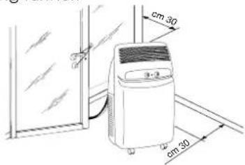
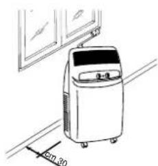
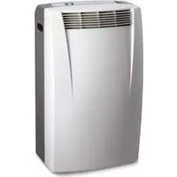
Install the appliance inside the room to be air conditioned, usually near a window or a perimeter wall. The internal unit must be located on the level. Also use the wheel blocks supplied. The intake zone (intake grill) and emission zone (outlet grill) of the internal unit should be kept clear of obstacles.
NB: Leave at least 30 cm between the wall and the appliance.
POSITIONING THE CONNECTING SHEATH
The sheath 4 connecting the external and internal units can be passed:
a) Through the crack of a window or door left ajar. Use the suckers prevent it from opening further.
b) Through a small crack (5.5 cm x 2.5 cm) in the bottom of a door or the frame of a window, using the sheath frame [20] provided.
natural_image
Line drawing of a small industrial air conditioner unit on a hallway, with no visible text or symbols.USING THE RAPID COUPLINGS
(models F400 and F300 only)
As an alternative to the methods described above, the sheath connecting the external and internal units can be passed through a 6 cm diameter hole in a wall communicating with the outside.
Rapid couplings in the model F400
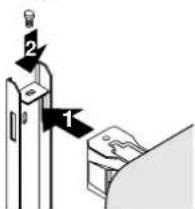
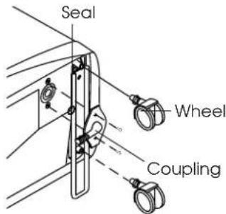
In this model, the connections of the external unit must be disconnected as follows:
1) Unplug the appliance from the main.
2) Remove the handle by undoing the two metric screws then remove the front panel.
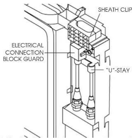
3) Remove the "U"-stay by undoing the two metric screws.
4) Remove the sheath clip by undoing the two metric screws.
natural_image
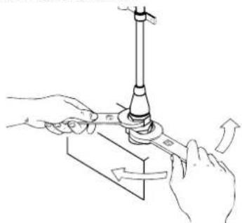
Illustration of hands using a tool to lift a mechanical component (no text or symbols)5) Use a number 24 spanner to undo the rotating union on the coupling. At the same time, use a number 21 spanner to hold the end of the flexible pipe steady. Repeat for the second union using a number 24 and a number 19 spanner.
6) Disconnect the condensate pipe from the pipe fitting.
7) Undo the two self-tapping screws holding the guard and remove the electrical connection block.
Avoid tight curves in the connection sheath
Setting up
Rapid couplings in model F300
In this model, the connections of the internal unit must be disconnected as follows:
1) Unplug the appliance from the main.
2) Remove the filters on the side.
3) Remove the rear door in the back panel by undoing the two screws.
4) Remove the metal "U"-stays fixing the pipes to the appliance (2).
natural_image
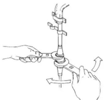
Illustration of hands using a tool to adjust or install a mechanical component, no text or symbols present5) Use a number 24 spanner to undue the rotating union on the coupling. At the same time, use a number 21 spanner to hold the end of the flexible pipe. Repeat for the second union using a number 24 and a number 19 spanner
6) Disconnect the condensate pipe from the pipe fitting.
7) Remove the electrical connection block.
Avoid tight curves in the connection sheath
Reconnecting the sheath in models F400 and F300
To reconnect the ends of the connecting sheath to the internal unit, repeat operations 1, 2, 3, 4, 5, 6 and 7 in reverse order, observing the following precautions:
- Before passing the sheath through the hole in the wall, protect the threaded ends of the rapid couplings with insulating tape or similar.
- Fit the top two refrigerant couplings to the bottom two and hand tighten them for several turns. Check they fit well before tightening with the spanners used previously
- After connecting the two refrigerant couplings, fix the stays.
- Check the seal of the refrigerant connections by covering the joins with a little soapy water. No soap bubbles should form.
Attention
We recommend that disconnection and connection of the rapid couplings be carried out by qualified personnel.
Setting up
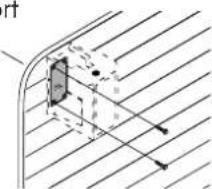
PREPARING THE EXTERNAL UNIT
The external unit can be placed on a terrace or balcony. In this case, the brackets should not be used.
natural_image
Line drawing of a kitchen interior with a suitcase and ladder (no text or symbols)The external unit can also be hung on a wall using the brackets .12 proceed as follows:
1) Fix the bracket 12
to the wall, taking care to position it as indicated in the figure. To make the holes, use the jig on the cover of the polystyrene packaging
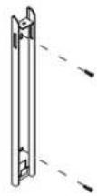
2) Screw the support blocks 13 the exter-
nal unit using the M4mm screws supplied (taking care to position them with the hole for the screw on the
natural_image
Pure technical diagram showing a curved pipe or channel with internal components and diagonal hatching (no text or symbols)3) Hook the external unit to the brackets, fixing it with the Mómm screw 17.
Alternatively, for temporary installation, the external unit can be suspended as shown in the figure. In this case, use the belts 340 applied hooked to the eyes 15 before inserting the eyes, remove the rubber bungs.
The external unit can be installed above or at the same level as the internal unit, providing the difference in level is not greater than 1.5 m. The air intake and outlet of the external unit should be kept clear of obstacles.
Leave at least 6 cm between the wall and the appliance.
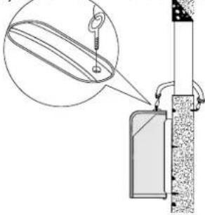
The drops of condensation formed during the air conditioning function (summer usage) is in part drained by evaporation by the external unit. The residual condensation exits the appliance through the hole at the base of the external unit. It is possible to utilise the
condensation drainage pipe-fitting 18 in order to make the condensation flow through a common rubber tube (not included). The drainage pipe-fitting must
be assembled onto the base of external unit (see illustration).
The external unit should be protected from rain, snow, drips from the roof and the sun.
Turning on and selecting the functions
CONNECTING TO THE ELECTRICAL MAIN AND TURNING THE APPLIANCE ON.
-
Before plugging the appliance into the electrical main, check that:
-
mains voltage conforms to the value indicated on the rating plate on the back of the appliance;
- the socket and power line are adequate for the required load;
- the socket is the right type for the plug, otherwise have the socket replaced;
- the socket is connected to an efficient earth installation. Failure to observe this accident prevention rule absolves the manufacturer of all liability.
Replacement of the power cable must be carried out by qualified personnel.
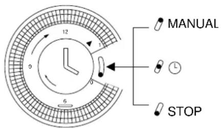
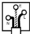
- Before setting the required function, check that the switch on the timer i9 in position 1 (manual).
If you wish to use the timer, position the switch in the intermediate position Ⓛ.
TIMER - SETTING THE TIME
As with all clocks, the programmer/timer must be set to the right time. If it is 16.00, rotate the pointers clockwise (follow the direction of the arrow) until you reach 16.00 p.m..
NB: never rotate the face in the opposite direction!
The timer is an electric clock and only works while the unit is connected to the mains. When it is unplugged or there is no electricity, the timer stops (the clock is "slow") and must be put right.
TIMER - PROGRAMMING
1) Set the times when the unit will function by pushing the teeth in the required interval towards the outside (each tooth represents 15 minutes).
2) Check that the timer indicates the exact time (see setting the time).
3) Choose the required function according to the instructions on the following page.
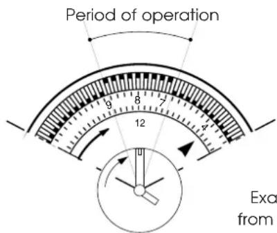
Example: from 7 to 9
In this mode, the unit will repeat the set programme every day.
N.B.: It is not necessary to modify the programme to exclude "timer" operation. Just turn the switch to 1 (manual).
Selecting functions
AS AIR CONDITIONER
With the unit turned off, the function selector 23 is in the "O" position. To turn the unit on in air conditioning mode, proceed as follows:
-
Rotate the function selector knob clockwise:
-
Place the large crystal symbol ✕ in line with the reference mark to operate the unit in air conditioning mode at maximum fan speed.
-
Place the small crystal symbol in line with the reference mark to operate the unit in air conditioning mode at minimum fan speed.
-
Now set the required temperature by rotating the room thermostat knob.
Note
The temperature is not expressed in degrees. We therefore recommend rotating the room thermostat knob to the maximum cool position. When room temperature has reached the required level, rotate the thermostat knob slowly clockwise until the thermostat is activated, turning the unit off. This programs the unit to the precise level of comfort required which will then be automatically maintained by the thermostat with considerable energy savings. When regulating the thermostat, the air conditioning function is temporarily interrupted and the unit continues to operate in fan only mode.
THIS UNIT EMPLOYS AN EXCLUSIVE CONDENSATION RECYCLING SYSTEM TO DISPOSE OF EXCESS MOISTURE. IN NORMAL CONDITIONS, CONDENSATION IS DISPOSED OF AUTOMATICALLY. WHEN THE HUMIDITY IS PARTICULARLY HIGH, AN EXCESS OF CONDENSATION MAY BUILT UP IN THE TANK. WHEN THIS HAPPENS, THE INDICATOR LIGHT. 28 COMES ON INDICATING THAT THE TANK SHOULD BE EMPTIED.
AIR PURIFICATION WITH FAN
Your air conditioning unit has two special high efficiency electrostatic 3M FILTRETETM filters. These filters, active in all modes, filter out extremely fine particles (down to 0.3 thousands of a millimetre).
If you want to purify the air by ventilating the room only, rotate the function selector 23 anticlockwise.
- Place the large symbol 📋 in line with the reference mark to operate the unit in air purification mode at maximum fan speed.
- Place the small symbol ≈ in line with the reference mark to operate the unit in air purification mode at minimum fan speed.
Functions/Warning lights
HEATING (mod. F300)
Rotate the function selector knob counter clockwise to the ⭐ symbol:
Note
The temperature is not expressed in degrees. We therefore recommend rotating the room thermostat knob to the maximum heat position. When the temperature in the room reaches the comfort level desired, the thermostat knob may be turned SLOWLY in a counter clockwise direction until the thermostat intervenes, turning off the operation. This programs the unit to the precise level of comfort required which will then be automatically maintained by the thermostat with considerable energy savings. When regulating the thermostat, the air conditioning function is temporarily interrupted and the unit continues to operate in fan only mode.
TURN THE APPLIANCE OFF
TO TURN THE UNIT OFF COMPLETELY, SET THE FUNCTION SELECTOR TO THE "O" POSITION AND UNPLUG FROM THE MAINS
THE START OF THE FUNCTIONS MAY UNDERGO SLIGHT DELAYS WITH RESPECT TO THE ROTATION OF THE SELECTOR.
THE LEDS
Led displays come on depending on the selected function or as warning of possible anomalies.
| FUNCTION | LED ✕/ [IMAGE] 24 | LED ≈ 25 | LED ✕ 26 (F300) |
| OFF | - | - | - |
| AIR-CONDITIONING | on* on | - | |
| PURIFYING | - on | - | |
| HEATING | - on | on |
* The leds will light up 3 minutes after the machine is turned on (that is, when the compressor starts to work). They will turn off when the temperature set by the thermostat is reached.
Recommendations
Follow these recommendations to achieve maximum efficiency from your air conditioning unit:
- Close the doors and windows in the room where the unit is functioning. The only exception is in the case of installation through a hole in the wall. In this case, you are recommended to allow a small amount of air to enter through a door or window to guarantee an adequate exchange of air.
- Do not install the heater in humid environments.
- Do not use the appliance outdoors.
- Mod. F300: Keep the appliance a safe distance from combustible surfaces
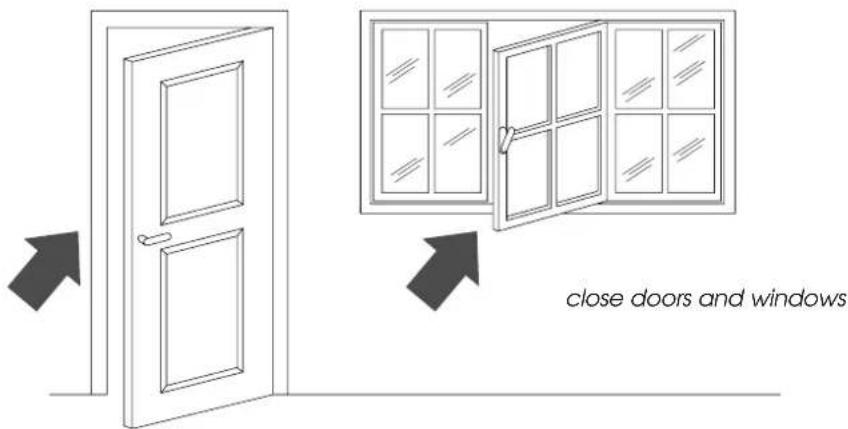
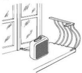
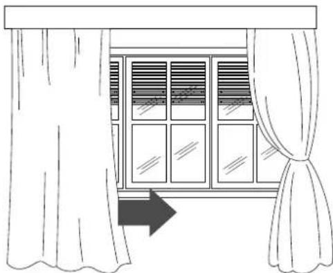
- Protect the room from direct exposure to the sun's rays by drawing the curtains and/or partially lowering the blinds so as to maximise energy savings.
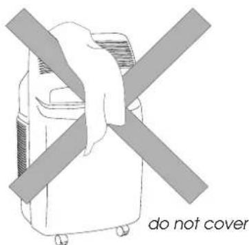
- Do not rest objects on the air conditioning unit.
- Do not obstruct the air intake or outlet.
• Make sure there are no heat sources in the room.
natural_image
Line drawing of a window with curtains and sheer curtains, no text or symbols presentlower the blinds or draw the curtains
- Make sure the unit is located on a level floor. If necessary, place the two blocking devices under the front wheels.
Cleaning
Before cleaning or maintenance, always turn the unit off by placing the selector in the "O" position and unplug from the mains.
CLEANING THE EXTERNAL UNIT
We recommend cleaning the unit with a slightly damp cloth then drying with a dry cloth. For safety reasons, do not wash the air conditioner with water.
Precautions
Never clean with benzene, alcohol or solvents. Never spray liquid insecticide or similar.
CLEANING THE AIR FILTERS.
To maintain the air conditioning unit at peak efficiency, you are recommended to:
- Clean the anti-bacteria filter weekly.
- Replace the FILTRETETM filter at the end of each season or when spent (follow the instructions on the unit near the filter).
The air purification filters are located behind the two intake grilles. The grilles in fact house the filters themselves.
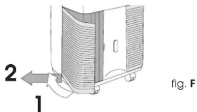
To clean the filters:
- Remove the intake grilles by rotating them outwards.
- Remove the first FILTRETE™ filter (white).
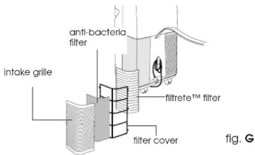
- To remove dust deposited on the anti-bacteria filter, use a vacuum cleaner. If very dirty, rinse repeatedly in warm water at a temperature of not more than 40^ C.
After washing, dry the filter. To replace, put the filters back into the filter holder, then hook the latter to the unit.
Do not clean the FILTRETE™ filter as this would reduce its filtering capacity.
BEGIN OF SEASON CHECKS
Check that the power cable and socket are undamaged and that the earth installation is efficient. Meticulously observe the installation norms.
END OF SEASON OPERATIONS
Empty the residual water by removing the bung in the drainage tube .18
Take out the condensation tank located in the rear of the unit and empty it. After replacing the bung, put the condensation tank back.
Clean the anti-bacteria filters and dry well before replacing.
Protect the unit from dust by covering with a plastic bag.
Troubleshooting
PROBLEM CAUSES REMEDY
| The unit does not work | the power is offthe plug is not inserted into the electrical outletthe function selector is in the “•” positionthe timer pointer is on STOPthe timer pin is in the position and it is not programmed to operate at that moment | waitplug inmove the selector to the desired positionset the timer pointer to the manual positionadjust the timer following the instructions given on page 23. |
| The unit works for only a short time | the thermostat has cut inthe external unit intake is obstructedthe fan is blocked | turn the thermostat counter clockwiseremove the obstructionscontact the Service Centre |
| The tank full light is on | condensate is not being drained externally remove the water through the drain tube | |
| The unit works but does not cool the room | windows opena heat source is operating in the room (burner, light, etc.) or there are a lot of peoplethermostat adjusted too highair filters cloggedthe output of the unit is insufficient for the conditions or size of the room | close the open windowremove the heat sourcereinsert the tube into its placeclean the filter or replace |
| The air conditioner does not heat sufficiently (mod. F300) | the air filter is dirtythe temperature setting is incorrectthe grill openings are blockedthe room is too big | clean the filter or replace itreset the temperatureremove the blockage |
Technical specification
RECOMMENDED OPERATING CONDITIONS
| Room temperature | 21 ÷ 32^ |
| Outside temperature | 21 ÷ 43^ |
TECHNICAL SPECIFICATION
Power supply see rating plate
Max. absorbed power in air conditioning "
Max. absorbed power when heating (mod. F300) "
Refrigerating capacity*
Number of fan speeds 2
Max. air flow 460 m ^3 /h
Dimensions of internal unit:
- width 452 mm
- height 800 mm
depth weight
Dimensions of external unit:
- width 465 mm
- height 480 mm
depth weight
* Standard conditions:
Room temperature 27°C
47% relative humidity
Outside temperature 35°C
41% relative humidity
This appliance contains substances which, if liberated into the atmosphere, would damage the ozone layer. Care should therefore be taken not to perforate the refrigerant circuit. At the end of its working life, delivery the air conditioning unit to a special collection centre.
ELECTRICAL CONNECTION (U.K. ONLY)
A) If your appliance comes fitted with a plug, it will incorporate a 13 Amp fuse. If it does not fit your socket, the plug should be cut off from the mains lead, and on appropriate plug fitted, as below. warning: Very carefully dispose of the cut off plug after removing the fuse: do not insert in a 13 Amp socket elsewhere in the house as this could cause a shock hazard. With alternative plugs not incorporating a fuse, the circuit must be protected by a 15 Amp fuse. If the plug is a moulded-on type, the fuse cover must be re-fitted when changing the fuse using a 13 Amp Asta approved fuse to BS 1362. In the event of losing the fuse cover, the plug must NOT be used until a replacement fuse cover can be obtained from your nearest electrical dealer. The colour of the correct replacement fuse cover is that as marked on the base of the plug.
B) If your appliance is not fitted with a plug, please follow the instructins provided below:
WARNING - THIS APPLIANCE MUST BE EARTHED IMPORTANT
The wires in the mains lead are coloured in accordance with the following code:
Green and yellow Earth
| Blue | Neutral |
| Brown | Live |
As the colours of the wires in the mains lead may not correspond with the coloured markings identifying the terminals in your plug, proceed as follows:
The green and yellow wire must be connected to the terminal in the plug marked with the letter E or the earth symbol
or coloured green or green and yellow.
The blue wire must be connected to the terminal marked with the letter N or coloured black.
The brown wire must be connected to the terminal marked with the letter L or coloured red.
natural_image
Line drawing of a portable air conditioner unit on a hallway, with no visible text or symbolsUTILISATION DES RACCORDS RAPIDES
natural_image
Illustration of hands using a tool to adjust or install a mechanical component (no text or symbols visible)natural_image
Illustration of hands performing a mechanical assembly with rotating components (no text or symbols)natural_image
Line drawing of a kitchen interior with a suitcase and ladder (no text or symbols)natural_image
Pure technical diagram showing a curved channel with internal components and diagonal lines, no text or symbols present.MINUTERIE: MISE À L'HEURE
natural_image
Line drawing of a window with curtains and sheer curtains, no text or symbols present* Conditions standards:
natural_image
Line drawing of a portable air conditioner unit on a hallway, with no visible text or symbolsnatural_image
Line drawing of hands operating a mechanical device with rotating arms (no text or symbols)natural_image
Illustration of hands performing a mechanical valve assembly with directional arrows (no text or symbols)natural_image
Line drawing of a kitchen sink with a bag and ladder, no text or symbols presentnatural_image
Line drawing of a window with curtains and sheer curtains, no text or symbols presentINSTALLATIE VAN DE BINNENEENHEID
natural_image
Line drawing of a portable air conditioner unit on a hallway, with a 20mm height measurement indicator (no text or symbols on the device itself)GEBRUIK VAN DE DIRECTE AANSLUITINGEN (uitsluitend mod. F400 en F300)
natural_image
Line drawing of hands operating a mechanical device with arrows indicating motion (no text or symbols)natural_image
Illustration of hands performing a mechanical valve assembly with directional arrows (no text or symbols)natural_image
Line drawing of a kitchen interior with a suitcase and ladder (no text or symbols)HET APPARAAT UIT TE SCHAKELEN
OM HET APPARAAT HELEMAAL AF TE ZETTEN, DE FUNCTIEKEUZEKNOP WEER OP "O" ZETTEN EN DE STEKKER UIT HET STOPCONTACT HALEN.
HET AANSLAAN VAN DE GEKOZEN FUNCTIES KAN ENIGSZINS VERTRAAGD GESCHIEDEN TEN OPZICHTE VAN HET DRAAIEN VAN DE KEUZEKNOP.
CONTROLELAMPJES
natural_image
Line drawing of a window with curtains and sheer curtains, no text or symbols presentnatural_image
Sketch of a person in uniform and cap using a machine (no text or symbols visible)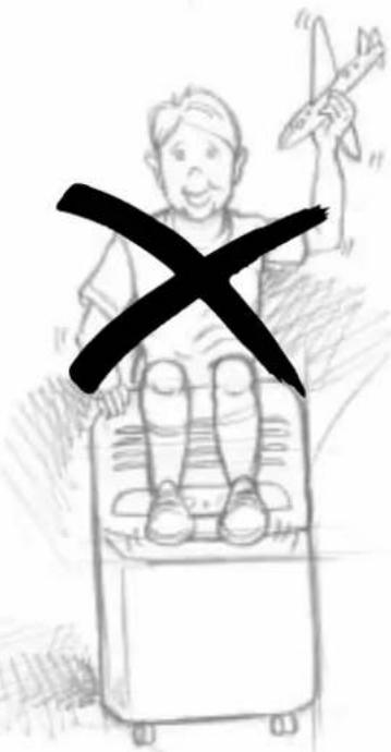
natural_image
Line drawing of a small industrial air conditioner unit with a 50mm height dimension labeled (no text or symbols on the device itself)USO DE LAS UNIONES RAPIDAS
natural_image
Illustration of hands using a tool to lift a mechanical component (no text or symbols)natural_image
Illustration of hands performing a mechanical assembly with rotating components (no text or symbols)natural_image
Line drawing of a kitchen interior with a coat and ladder (no text or symbols)TIMER: REGULACION DE LA HORA
natural_image
Line drawing of a window with curtains and sheer curtains, no text or symbols presentnatural_image
Sketch of a person in uniform and cap using a machine (no text or symbols visible)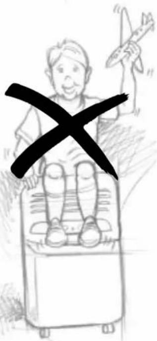
natural_image
Line drawing of a small air conditioner on a hallway with a door and window in the background (no text or symbols)natural_image
Illustration of hands using a tool to adjust or install a mechanical component (no text or symbols visible)natural_image
Illustration of hands performing a mechanical assembly with rotating components (no text or symbols)natural_image
Line drawing of a kitchen interior with a suitcase and ladder (no text or symbols)natural_image
Pure technical diagram showing a curved pipe or channel with internal components and directional arrows, no text or symbols present.17
RELÓGIO PROGRAMADOR: ACERTAR A HORA
natural_image
Line drawing of a window with curtains and sheer curtains, no text or symbols presentPROBLEMAS CAUSAS SOLUÇÕES
natural_image
Sketch of a person in a hat and coat using a device (no text or symbols visible)
natural_image
Line drawing of a small industrial machine on a conveyor belt with a 50-degree angle indicator (no text or symbols present)natural_image
Illustration of hands using a tool to lift a mechanical component (no text or symbols present)natural_image
Illustration of hands performing a mechanical valve assembly with rotating components (no text or symbols)natural_image
Line drawing of a kitchen counter with a small bag and shelf, no text or symbols presentnatural_image
Pure geometric diagram showing intersecting lines and a shaded rectangle, without any text, numbers, or symbols.natural_image
Line drawing of a window with curtains and sheer curtains, no text or symbols presentnatural_image
Gray rectangular image with a white crosshair and horizontal line at bottom (no text or symbols)

- UTILIZZO DEI RACCORDI RAPIDI
- (solo mod. F400 e F300)
- TIMER: REGOLAZIONE DELL'ORA
- What is Pinguino Pinguino and SuperPinguino
- Important Safe-guards
- Setting up
- PREPARING THE INTERNAL UNIT
- POSITIONING THE CONNECTING SHEATH
- USING THE RAPID COUPLINGS
- (models F400 and F300 only)
- Rapid couplings in the model F400
- Rapid couplings in model F300
- Reconnecting the sheath in models F400 and F300
- Attention
- PREPARING THE EXTERNAL UNIT
- Turning on and selecting the functions
- CONNECTING TO THE ELECTRICAL MAIN AND TURNING THE APPLIANCE ON.
- Replacement of the power cable must be carried out by qualified personnel.
- TIMER - SETTING THE TIME
- TIMER - PROGRAMMING
- Selecting functions
- AS AIR CONDITIONER
- Note
- AIR PURIFICATION WITH FAN
- Functions/Warning lights
- HEATING (mod. F300)
- TURN THE APPLIANCE OFF
- THE LEDS
- Recommendations
- Cleaning
- CLEANING THE EXTERNAL UNIT
- Precautions
- CLEANING THE AIR FILTERS.
- BEGIN OF SEASON CHECKS
- END OF SEASON OPERATIONS
- Troubleshooting
- Technical specification
- ELECTRICAL CONNECTION (U.K. ONLY)
- WARNING - THIS APPLIANCE MUST BE EARTHED IMPORTANT
- UTILISATION DES RACCORDS RAPIDES
- MINUTERIE: MISE À L'HEURE
- INSTALLATIE VAN DE BINNENEENHEID
- GEBRUIK VAN DE DIRECTE AANSLUITINGEN (uitsluitend mod. F400 en F300)
- HET APPARAAT UIT TE SCHAKELEN
- CONTROLELAMPJES
- USO DE LAS UNIONES RAPIDAS
- TIMER: REGULACION DE LA HORA
- RELÓGIO PROGRAMADOR: ACERTAR A HORA
Brand : DELONGHI
Model : PAC F400
Category : Air Conditioning