
UFG 300 - Remote control KATHREIN - Free user manual and instructions
Find the device manual for free UFG 300 KATHREIN in PDF.
| Product Type | Programming remote control for UFO® compact modules |
| Brand | Kathrein |
| Model | UFG 300 |
| Dimensions (without cable) | 220 x 75 x 25 mm |
| Weight | 0.6 kg |
| Power supply | 5 V / 100 mA, supplied by the UFO® compact module or UFX 312/314 demultiplexer via the connection cable |
| Current consumption | 100 mA |
| Display | LCD screen, 4 lines of 20 characters |
| Keyboard | 12 ergonomic function keys with wear-resistant tactile feel |
| Direct input | Numeric characters (decimal and hexadecimal) and alphanumeric via virtual keyboard |
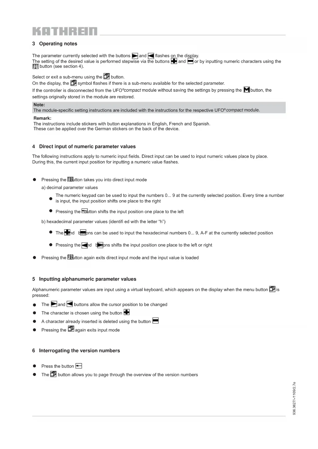
| Connection | 1.4 m spiral cable with mini DIN 6-pin plug, anti-kink protection |
| USB port | For firmware update via PC |
| Housing protection type | IP 50 according to EN 60529 |
| Permissible ambient temperature | +5 °C to +50 °C |
| Compliance | EN 50083-2 and RoHS |
| Main functions | Programming of processing channel parameters, language setting, establishing cable NIT table, direct value input, viewing software versions |
| Care and cleaning | LCD screen fragile, avoid shocks; do not bend the cable; clean with a soft, dry cloth; do not open the device |
| Safety | Only connect to UFO® compact processing channels; do not open; dispose of according to WEEE directive (2002/96/EC) |
| Spare parts and repairability | No user-serviceable parts; firmware update possible via PC |
| Available languages | German (default), French, Spanish; other languages via system menu |
Frequently Asked Questions - UFG 300 KATHREIN
User questions about UFG 300 KATHREIN
0 question about this device. Answer the ones you know or ask your own.
Ask a new question about this device
Download the instructions for your Remote control in PDF format for free! Find your manual UFG 300 - KATHREIN and take your electronic device back in hand. On this page are published all the documents necessary for the use of your device. UFG 300 by KATHREIN.
USER MANUAL UFG 300 KATHREIN
- LCD display with 4 lines and 20 characters per line for display of the settings and operating parameters
- 12 ergonomically arranged function buttons with rub-proof labelling for entering the channel unit parameters
- Numeric characters can be input directly
- Spiral cable, 1.4 m long, non-kinking, 6-pin mini DIN plug for connection to modules
- USB interface for software-update via PC
Power supply (5 V/100 mA) to controller via modules
Complies with: EN 50083-2 and RoHS conformity - Dimensions without cable (mm): 220 × 75 × 25
- Packing unit/weight (pc./kg): 1/0.6
| Type Order no. | Power consumption (mA) | Power supply (V) | Housing protection class | Permissible ambient temperature range (°C) |
| UFG 300 20610082 | 100 | 5 | IP 50 to EN 60529 | +5 to +50 |
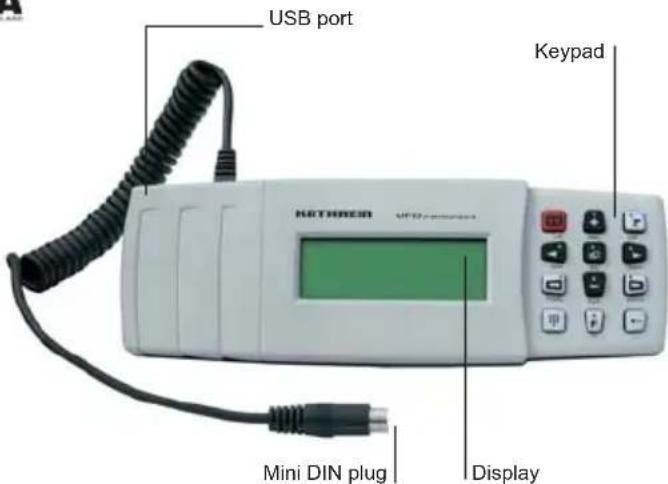
1 Explanation of the keypad
The numbers, letters and special characters assigned to a button are printed on the button or below the button on the housing.
- Increase value
Decrease value
Next parameter
Previous parameter
Next channel unit
Previous channel unit
Sub-menu
M Save all parameter values
Help text for the currently selected parameter
Display the software versions of the controller and channel unit, or move the cursor to the left in numeric input mode
Changing the edit mode:
-
Press - Change into numeric input mode
-
Press - Load the input and exit numeric input mode
E System menu:
- Language setting
- Special functions (cable NIT)
Note:
The most up-to-date version of these user instructions can be found on the Kathrein homepage under "www.kathrein.de → Service → Operating manuals"
3 Operating notes
The parameter currently selected with the buttons and flashes on the display.
The setting of the desired value is performed stepwise via the buttons and or by inputting numeric characters using the button (see section 4).
Select or exit a sub-menu using the button.
On the display, the symbol flashes if there is a sub-menu available for the selected parameter.
If the controller is disconnected from the UFO®compact module without saving the settings by pressing the button, the settings originally stored in the module are restored.
Note:
The module-specific setting instructions are included with the instructions for the respective UFO®compact module.
Remark:
The instructions include stickers with button explanations in English, French and Spanish. These can be applied over the German stickers on the back of the device.
4 Direct input of numeric parameter values
The following instructions apply to numeric input fields. Direct input can be used to input numeric values place by place. During this, the current input position for inputting a numeric value flashes.
- Pressing the button takes you into direct input mode
a) decimal parameter values
The numeric keypad can be used to input the numbers 0...9 at the currently selected position. Every time a number is input, the input position shifts one place to the right
- Pressing the button shifts the input position one place to the left
b) hexadecimal parameter values (identifi ed with the letter "h")
The and boons can be used to input the hexadecimal numbers 0...9,A-F at the currently selected position
- Pressing the end buttons shifts the input position one place to the left or right
- Pressing the button again exits direct input mode and the input value is loaded
5 Inputting alphanumeric parameter values
Alphanumeric parameter values are input using a virtual keyboard, which appears on the display when the menu button is pressed:
The and buttons allow the cursor position to be changed
The character is chosen using the button
A character already inserted is deleted using the button
- Pressing the 2 again exits input mode
6 Interrogating the version numbers
Press the button
The button allows you to page through the overview of the version numbers
7 Settings at system level
The central controller is selected by pressing the double arrow buttons " 一 _ 一 and 一 _ 一 ^ 一 . The procedure is exactly the same as for the channel units; when selected the controller has the same priority as a channel unit.
7.1 Setting the language
Pressing the "F" button brings you to the system menu, where the language can be set and the version numbers interrogated, the system password set and the cable NIT settings made.
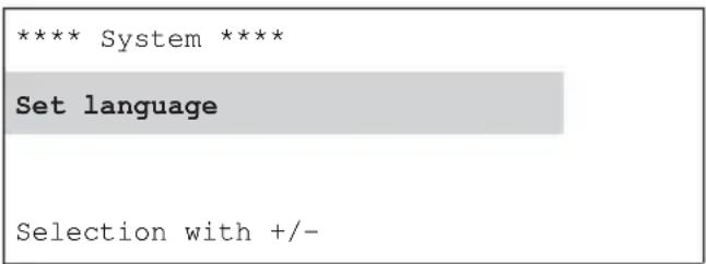
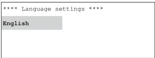
System menu "Set language" sub-menu
The instructions for this can be found at the start of the setup instructions, since these menus are accessible at the channel unit level and relevant to it.
7.2 Settings for compiling the cable NIT
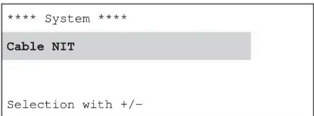
A UFX 312 or UFX 314 (BN 20610071) data bus de-multiplexer is required for compiling the cable NIT. The "Cable NIT" entry in the system menu can be selected only if the central controller is connected to a demultiplexer (control port).
Pressing the "F" button brings you to the system menu, where the cable NIT settings can be made. Press the "+" and "Cable NIT" buttons in the system menu.
Pressing the "Sub-menu" button activates the sub-menu; pressing the "Sub-menu" button again deactivates it.
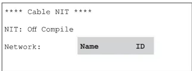
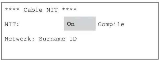
System menu "Cable NIT" sub-menu
Press the " " and "▶" buttons to select the desired parameter "Off/On", "Compile", "Name" or "ID". Press the "Sub-menu" button to activate the selected parameter and open the respective sub-menu.
7.2.1 Setting the name and the network ID for the cable NIT
Press the “<” and “>” buttons to select the desired parameter “on”, “Compile”, “Name” or “ID”.
Press the "Sub-menu" button to activate the selected parameter and open the respective sub-menu.
The network name is set by adding " ^+ " or removing " ^ 一 " characters at the flashing cursor in the third (name) line.
The character to be added is selected by using the “ ” and “ ” buttons to move the cursor within the first two lines.
The maximum number of characters is 40.
Exit the menu by pressing the "Sub-menu" button; this saves the set value.
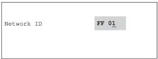
The network ID should only be set if the operator applied for and was granted the ID by the ETSI.
The preset value (FF01) is intended for networks without a specific network ID.
The network ID is selected digit by digit using the “ ” and “ ” buttons and is changed using the “+” and “-” buttons.
Exit the menu by pressing the "Sub-menu" button; this saves the set value.
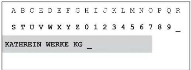
"Name" sub-menu "ID" sub-men
7.2.2 Compiling the cable NIT, switching the cable NIT on and off
The controller carries the NIT compilation process through to completion after it has been started manually with the “+” or “-” button. The new cable NIT is created and then sent to the channel units. The procedure can be aborted by pressing the “←” button (leading to the error message shown below). A progress bar is displayed in the bottom line of the display during the compilation process.
When the cable NIT is complete it is saved and can now be switched on and off as required. To do this, use the “<” and “>” buttons to select the “Cable NIT” “on/off” sub-menu and use the “+” and “-” to make the change-over.
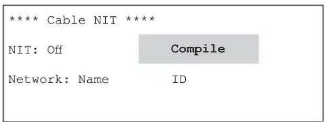
"Cable NIT" sub-menu
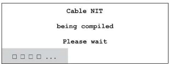
"Cable NIT" sub-menu (display during NIT compilation)
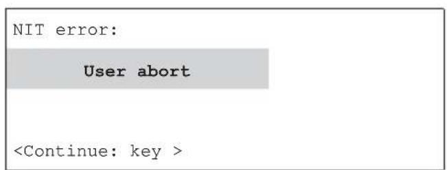
"Cable NIT" sub-menu (display if aborted)
"Cable NIT" sub-menu
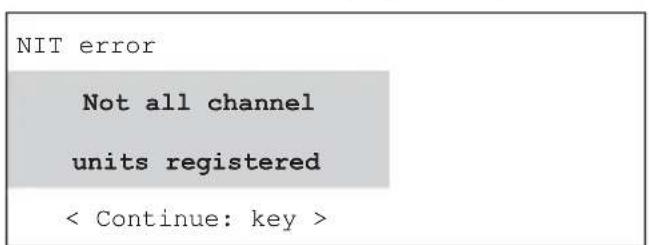
The following error messages may appear during cable NIT compilation:
"Cable NIT" sub-menu
"Cable NIT" sub-menu
The following conditions must be fulfilled to compile the NIT successfully:
The system must be fully set up
- All digital channel units must be in operation with their front ends clicked into place
Note: The NIT compilation cannot be performed if the HF output signal is switched on at an unused channel unit.
7.2.3 Planning a system with cable NIT
When planning a system with cable NIT, the following should be noted regarding the position of the modules:
Case 1: All modules in use control the functioning of the cable NIT.
In this case the position of the individual modules in the system is immaterial and irrelevant.
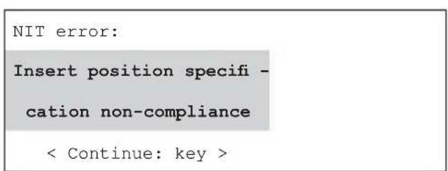
Case 2: UFO compact system made up of different module types
If not all the modules in use are capable of compiling a cable NIT, the insert position specification described below must be complied with.
Insert position specification:
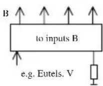
For NIT compilation to function properly, each SAT level must be reached by at least one channel unit that is capable of compiling an NIT.
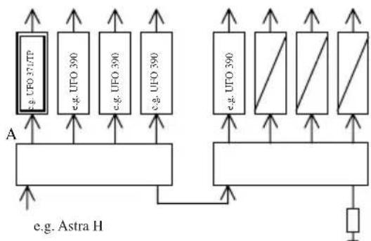
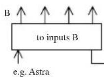
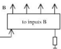
a) Compilation with an input distributor row
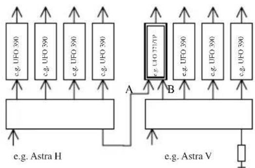
b) Two polarisations
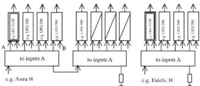
c) Two input distributor rows, several polarisations (with option UFS 340)
Note:
The cable NIT can be used only on transponders that are fitted with an NIT- compilation-capable channel unit.
8 Software Update
8.1 General Information
The software for the UFO® compact controller consists of two components:
a) Bootloader: software for exchanging the firmware
b) Firmware: software for configuration of UFO compact channel units
The firmware can be exchanged using a PC programme ("bootload.exe").
Important note:
No connection to the UFO compact system is necessary to perform a software update.
Power is provided by the USB interface.
8.2 Programming the firmware (software update)
- Preconditions:
a) PC/laptop with the following system requirements:
- USB port
- Operating system Windows 2000 or Windows XP
- Installed USB driver for UFG 300 (see section 7.3)
- Administrator rights for installation of the USB driver for UFG 300
b) USB cable
c) PC software "Bootload.exe" with version 2.10 or higher
- Update procedure:
a) Use the USB cable to connect the free USB interface on the PC to the USB interface on the UFO compact controller
b) Install the USB driver for UFG 300 on the PC, if this has not previously been done (see section 7.3).
The following steps refer to the Windows update software "bootload.exe":
c) Start "bootload.exe"
d) Press "setup"
e) Select the COM port chosen in step j) in section 7.3
f) Press "Select file"
g) Select firmware "setup.bin"
h) Press "Open"
i) Press "Download". This starts the software update
j) The update procedure is completed when the progress display disappears and the message "Start application" appears.
8.3 Installation of the USB driver for the UFG 300
Installation under Windows XP is shown as an example. Installation under Windows 2000 is similar.
a) Log in as a Windows user with administrator rights
b) Unzip the file with the USB driver (e.g. "CDM 2.00.00.zip") into a suitable directory
c) Use the USB cable to connect the free USB interface on the PC to the USB interface on the UFO compact controller
d) Wait until the Windows wizard for installation of new hardware appears
e) Open the dialogue "Create connection with Windows Update"
- Select the following choices:
"Should a connection with Windows Update be created to search for software?"
"No, no this time" - Press "Continue"
f) Dialogue "Selection of the Installation Source"
- Select the following choices:
"How do you wish to proceed?"
"Install software from a list or from a specific source" - Press "Continue"
g) Dialogue "Search and Installation Options"
- Select "Search these sources for the most appropriate driver"
- Deactivate "Search interchangeable media"
- Activate "Search the following source also"
- Press "Search"
- Select the directory holding the USB driver from step a)
- Press "OK"
- Press "Continue"
h) Dialogue "Finish the Wizard"
Press "Finish"
i) If steps e) to h) have already been run through twice, continue with step j).
Otherwise repeat steps e) to h) once again
Note: The required "USB Serial Port" driver will not be installed until the second pass
j) Check that the USB driver for the UFG 300 has been correctly installed.
This is done by starting the Windows Device Manager as follows:
- Call up the Control Panel by "Start → Settings → Control Panel"
- Start the "System" applet
- Select the "Hardware" tab
- Press "Device Manager"
An entry "USB Serial Port" must appear under both "COM" and "LPT" connections, followed by the name of a COM Port.
Make a note of the COM Port, since you will need to enter it later in step e) when programming the firmware.
If no entries are shown:
- Close the Device Manager again
- Break the USB connection between the controller and the PC
- Wait a few seconds and then re-establish the USB connection between the controller and the PC
- Start the Device Manager and, as described above, once again search for the "USB Serial Port" entry
9 Warning and safety notes
- The LCD display is fragile and can be damaged if the unit is dropped.
- Do not kink the cable!
- Plug the mini DIN-plug only into UFO® compact channel units
- Do not open the unit!
Electronic equipment is not household waste - it must be disposed of properly in accordance with Directive 2002/96/EC OF THE EUROPEAN PARLIAMENT AND THE COUNCIL dated 27th January 2003 on waste electrical and electronic equipment (WEEE). At the end of its service life, take this device for disposal at a designated public collection point.
Commande
UFG 300 20610082

- 1 Explanation of the keypad
- Note
- 3 Operating notes
- Remark
- 4 Direct input of numeric parameter values
- 5 Inputting alphanumeric parameter values
- 6 Interrogating the version numbers
- 7 Settings at system level
- 7.1 Setting the language
- 7.2 Settings for compiling the cable nit
- 7.2.1 Setting the name and the network id for the cable nit
- 7.2.2 Compiling the cable nit, switching the cable nit on and off
- 7.2.3 Planning a system with cable nit
- Insert position specification
- 8 Software update
- 8.1 General information
- Important note
- 8.2 Programming the firmware (software update)
- 8.3 Installation of the usb driver for the ufg 300
- 9 Warning and safety notes
- Commande
Brand : KATHREIN
Model : UFG 300
Category : Remote control