
SCPFWMSV2 - Flat screen mount 3M - Free user manual and instructions
Find the device manual for free SCPFWMSV2 3M in PDF.
| Product Type | Foldable wall mount for projector |
| Brand | 3M |
| Model | SCPFWMSV2 |
| Intended Use | SCP700 Series Projectors (Super Close Projection System) |
| Maximum Vertical Load | 22.7 kg (50 lb) |
| Minimum Pull-out Resistance | 136 kg (300 lb) |
| Material | Steel |
| Wall Mounting | Solid wood, concrete or cinder blocks (optional bracket required) |
| Adjustments | Arm extension, vertical tilt, horizontal rotation |
| Included Cables (MSV2 model) | USB 4m, VGA 4m, PC audio 1.8m and 3m, speaker amplifier power supply |
| Optional Accessories | 3M Wall Bracket (78-6969-9962-8), 3M Security Kit (78-6969-9961-0) |
| Kit Contents | Screws, wall plugs, cable ties, thumbscrews, etc. (details in manual) |
| Warranty | 1 year for wall mount |
| Installation | Installation by two experienced installers recommended |
| Safety Instructions | Do not climb, do not hang, avoid pinch points |
| Maintenance | Periodically inspect attachments and cables |
| Environment | Indoor only, temperature 10-35°C, humidity 10-80% non-condensing |
| Country of Origin | United States |
Frequently Asked Questions - SCPFWMSV2 3M
User questions about SCPFWMSV2 3M
0 question about this device. Answer the ones you know or ask your own.
Ask a new question about this device
Download the instructions for your Flat screen mount in PDF format for free! Find your manual SCPFWMSV2 - 3M and take your electronic device back in hand. On this page are published all the documents necessary for the use of your device. SCPFWMSV2 by 3M.
USER MANUAL SCPFWMSV2 3M
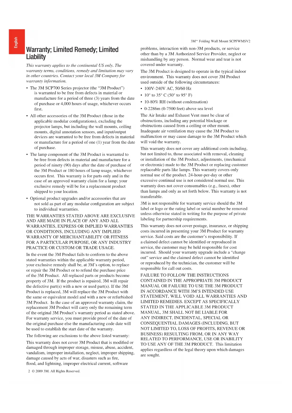
3M™ Folding Wall Mount SCPFWMSV2
For use with 3M^TM Super Close Projection System Installation Instructions
Warranty; Limited Remedy; Limited Liability
This warranty applies to the continental US only. The warranty terms, conditions, remedy and limitation may vary in other countries. Contact your local 3M Company for warranty information.
- The 3M SCP700 Series projector (the "3M Product") is warranted to be free from defects in material or manufacture for a period of three (3) years from the date of purchase or 4,000 hours of usage, whichever occurs first.
- All other accessories of the 3M Product (those in the applicable modular configurations), excluding the projector lamps, but including the wall mounts, ceiling mounts, digital annotation sensors, and input/output devices are warranted to be free from defects in material or manufacture for a period of one (1) year from the date of purchase.
- The lamp component of the 3M Product is warranted to be free from defects in material and manufacture for a period of ninety (90) days after the date of purchase of the 3M Product or 180 hours of lamp usage, whichever occurs first. This warranty is for parts only and in the case of an approved warranty claim for a lamp; your exclusive remedy will be for a replacement product shipped to your location.
- Optional product upgrades and/or accessories that are not sold as part of any modular configuration are subject to individual warranties.
THE WARRANTY STATED ABOVE ARE EXCLUSIVE AND ARE MADE IN PLACE OF ANY AND ALL WARRANTY, EXPRESS OR IMPLIED WARRANTYS OR CONDITIONS, INCLUDING ANY IMPLIED WARRANTY OF MERCHANTABILITY OR FITNESS FOR A PARTICULAR PURPOSE, OR ANY INDUSTRY PRACTICE OR CUSTOM OR TRADE USAGE.
In the event the 3M Product fails to conform to the above stated warranties within the applicable warranty period, your exclusive remedy shall be, at 3M's option, to replace or repair the 3M Product or to refund the purchase price of the 3M Product. All replaced parts or products become property of 3M. If the product is repaired, 3M will repair the defective part(s) with a new or used part(s). If the 3M Product is replaced, 3M will replace the 3M Product with the same or equivalent model and with a new or refurbished 3M Product. In the case of an approved warranty claim, the replacement 3M Product will carry only the remaining term of the original 3M Product's warranty period as stated above. For warranty service, you must provide proof of the date of the original purchase else the manufacturing code date will be used to establish the start date of the warranty.
The following are exclusions to the above listed warranty:
This warranty does not cover 3M Product that is modified or damaged through improper storage, misuse, abuse, accident, vandalism, improper installation, neglect, improper shipping, damage caused by acts of war, disasters such as fire, flood, and lightning, improper electrical current, software
problems, interaction with non-3M products, or service other than by a 3M Authorized Service Provider, neglect or mishandling by any person. Normal wear and tear is not covered under warranty.
The 3M Product is designed to operate in the typical indoor environment. This warranty does not cover 3M Product used outside of the following circumstances:
100V-240VAC,50/60Hz
10^ to 35^ (50^ to 95^)
- 10 - 80% RH (without condensation)
- 0-2286m (0-7500 feet) above sea level
The Air Intake and Exhaust Vent must be clear of obstructions, including any potential blockage or obstructions caused from a ceiling or other mount.
Inadequate air ventilation may cause the 3M Product to malfunction or may cause damage to the 3M Product which will void the warranty.
This warranty does not cover any additional costs including, but not limited to, those associated with removal, cleaning or installation of the 3M Product, adjustments, (mechanical or electronic) made to the 3M Product or replacing customer replaceable parts like lamps. This warranty covers only normal use of the product. 24-hour-per-day or other excessive continual use is not considered normal use. This warranty does not cover consumables (e.g., fuses), other than lamps and only as set forth below. This warranty is not transferable.
3M is not responsible for warranty service should the 3M label or logo or the rating label or serial number be removed unless otherwise stated in writing for the purpose of private labeling for partnership requirements.
This warranty does not cover postage, insurance, or shipping costs incurred in presenting your 3M Product for warranty service. Said costs are the customer's responsibility. If a claimed defect cannot be identified or reproduced in service, the customer may be held responsible for cost incurred. Should your warranty upgrade include a "change out" service and the claimed defect cannot be identified or reproduced by the technician, the customer will be responsible for call out costs.
FAILURE TO FOLLOW THE INSTRUCTIONS CONTAINED IN THE APPROPRIATE 3M PRODUCT MANUAL OR FAILURE TO USE THE 3M PRODUCT IN ACCORDANCE WITH 3M'S INTENDED USE STATEMENT, WILL Void ALL WARRANTY AND LIMITED REMEDIES. EXCEPT AS SPECIFICALLY STATED IN THE APPLICABLE 3M PRODUCT MANUAL, 3M SHALL NOT BE LIABLE FOR ANY INDIRECT, INCIDENTAL, SPECIAL OR CONSEQUENTIAL DAMAGES (INCLUDING, BUT NOT LIMITED TO, LOSS OF PROFITS, REVENUE OR BUSINESS) RESULTING FROM, OR IN ANY WAY RELATED TO PERFORMANCE, USE OR INABILITY TO USE ANY OF THE 3M PRODUCT. This limitation applies regardless of the legal theory upon which damages are sought.
3M^TM Folding Wall Mount SCPFWMSV2
For warranty support, please call or write your local 3M office or a 3M Authorized Service Provider to obtain RMA # (Return Material Authorization Number) before returning the product. If you are inside the Continental United States of America, please contact 3M Customer Service at 800-328-1371 or email meetings@mmm.com.
What 3M Will Do To Correct Problems:
If your 3M Product requires service, 3M will ask you to bring or send the 3M Product, securely packaged in its original container or equivalent, along with proof of the date of original purchase, to your 3M Service Dealer or 3M Service Center.
3M will, at its option, repair or replace the defective unit without charge for parts or labor. Return of the 3M Product will be at 3M's expense.
When warranty service involves the exchange of the 3M Product or of a part, the item replaced becomes 3M property. The exchanged 3M Product or part may be new or previously refurbished to the 3M standard of quality, and at 3M's option, the replacement may be another model of like kind and quality.
3M's liability for replacement of the warranted 3M Product or part will not exceed the original retail selling price of the 3M Product. Exchange or replacement products or parts assume the remaining warranty period of the product covered by this limited warranty. However, each replacement lamp carries the limited 90-day warranty stated above.
Safety Instructions
Please read and follow all safety information contained in these instructions prior to installation and use of the folding or fixed wall mounts. Retain these instructions for future reference.
Intended Use
The folding wall mount is intended to provide wall mounting of the 3M^TM Super Close Projection System SCP700 Series projectors to the wall as described in the Installation Instructions. It is expected that all installers and users be fully aware of safe operation of this product. Other applications have not been evaluated by 3M and may lead to an unsafe condition.
Explanation of Signal Word Consequences
WARNING: Indicates a potentially hazardous situation, which if not avoided, could result in death or serious injury and/or property damage.
CAUTION: Indicates a potentially hazardous situation, which if not avoided, may result in minor or moderate injury and/or property damage.
Summary of device labels containing safety information
Caution: Pinch Hazard

Warning: Do not hang on the product

Attention: Read Accompanying Documentation
Caution: Hot Surface
Warning: Do not look into the projector lamp
WARNING
To reduce the risk associated with all applicable hazards:
- Read and follow all safety information contained in the Installation Instructions and Product Safety Guide prior to installing, using or servicing the wall mount. Retain these instructions for future reference.
To reduce the risk associated with choking:
To reduce the risk associated with impact:
- Do not allow children access to small parts and/or packaging materials.
- The 3M Wall Mount Bracket is required hardware when installing the 3M Wall Mount onto concrete block walls and stud walls.
- The Wall Mount Bracket must be installed right side out (refer to installation instructions for details).
- If the 3M Wall Mount Bracket screws can not be driven into wall studs, do not install the bracket or the 3M system until the wall is properly reinforced.
- Always provide proper adult supervision when using the wall mounted projector around children.
- Do not use excessive force in opening or closing the folding arm of the wall mount.
- Proper installation and servicing must be performed by experienced installers as outlined in the installation instructions.
- This wall mount is to be used for mounting 3M^TM Super Close Projection System SCP700 Series projectors only. It has not been tested for other applications.
- Inspect the wall mount periodically to ensure all fasteners remain tightened and that no damage has occurred. Repair or replace all issues found prior to further use.
- Do not modify the physical aspects of the wall mount.
- Do not install on a mounting structure or surface that is prone to vibration, movement or chance of being impacted.
- The wall mounting structure or surface must be capable of supporting a minimum of 50 lbs vertical load. If not, the wall must be reinforced per the Installation Instructions prior to mounting.
- The wall mounting structure or surface must be capable of supporting a minimum of 300 lbs pull out force. If not, the wall must be reinforced per the Installation Instructions prior to mounting.
- Recommended mounting structure or surface is to solid wood (a minimum of 34 plywood mounted to a minimum of two studs) or to solid concrete. If the wall mount is to be installed on any other structure or surface, use suitable hardware and/or materials which are commercially available. This hardware and/or materials must be determined by an experienced installer.
- Do not climb on, hang on or place any added weight other than the projector on the fixed or folding wall mount.
WARNING
To reduce the risk associated with hazardous voltage:
- Do not re-route the factory installed cables of the folding wall mount from the bottom of the arm to the bottom of the base in any way (refer to the Installation Instructions). Pinching or wearing of the cables must be avoided. If any additional cables are added to the base, refer to the Installation Instructions. Inspect cables periodically for damage and repair all issues found prior to further use.
- Always disconnect the projector power cord from electrical outlet prior to any servicing.
- Do not install the wall mount in an outdoor or wet environment.
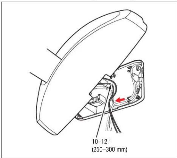
- Do not stuff excess cable lengths under the wall mount cover once base installation is complete.
To reduce the risk associated with fire:
- Do not install the wall mount near a heater, a fireplace or any other source of direct heat energy.
CAUTION
To reduce the risk associated with pinch points:
- Keep hands and fingers away from all moving parts to avoid pinch point injury.
To reduce the risk associated with lifting:
Always use two experienced installers for installation of the wall mounts per the Installation Instructions due to weight and handling concerns.
To reduce the risk associated with impact:
- When installing the Wall Mount Bracket, use only the Long Anchors included with the bracket.
SAVE THESE INSTRUCTIONS
1.0 Kit Contents
Installation Instructions
USB Cable 4m
VGA Cable 4m
6x Cable ties
3x M6*25 Screws (for mounting projector)
2x 1-1/2" Lag Bolts
2x12'' Lag Anchors
2x 2-1/2" Lag Bolts
2x 1-1/2" Lag Anchors
SCPFWMSV2 Only
1.8 m PC Audio Cable
3 m PC Audio Cable
Power Supply for Speaker Amp
Power Cord for Speaker Amp
EU to UK power outlet adapter (EU/UK only)
DC Power Cord (power from I/O to Speaker Amp)
2.0 Optional Accessories
3M^TM Wall Mount Bracket (78-6969-9962-8)
3M^TM Security Kit (78-6969-9961-0)
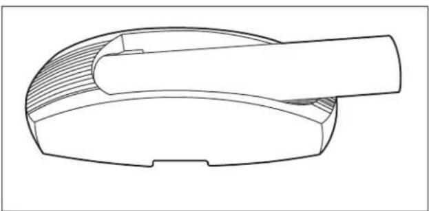
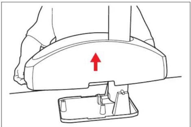
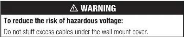
3.0 Remove the Cover
3.1 Remove the Folding Wall Mount from the packaging and set base-down on a table.
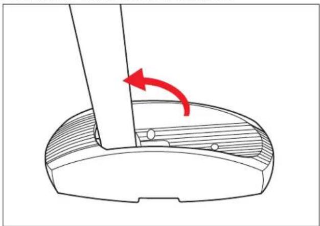
3.2 Swing the arm up until it locks in place.
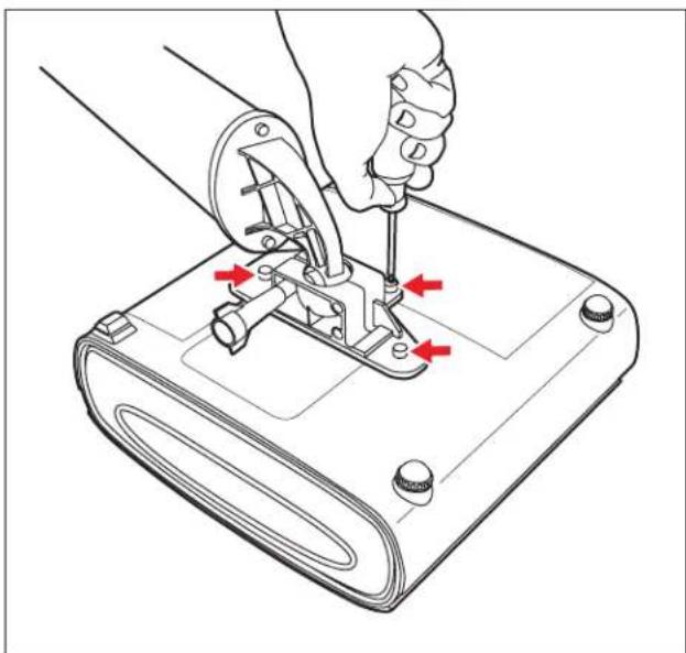
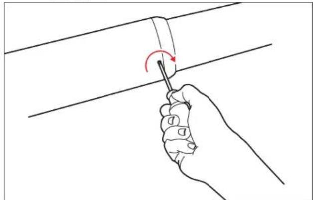
3.3 Using a Phillips (+) screwdriver, remove the three screws holding the cover to the base.
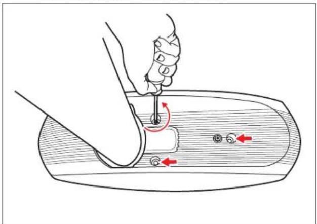
3.4 Lift the cover off the base and set aside.
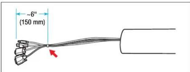
4.0 Route Cables
4.1 Feed the USB, VGA, and optional control cables through the arm. Align the cable ends and secure about 6 inches (150 mm) from the end using a cable tie.
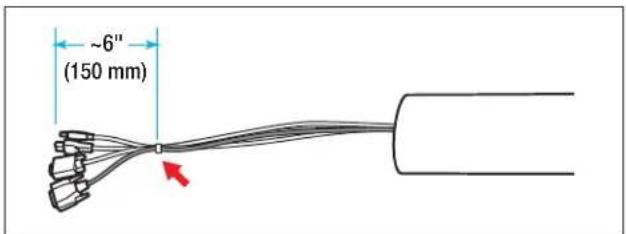
Note: The optional control cable is shipped with the 3M^rw I/O Module.
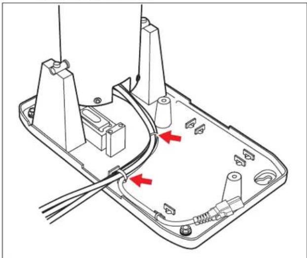
4.2 Align the cables alongside the power cable and secure using cable ties.
5.0 Solid Wall Installation
(For Concrete Block or Stud Walls, Skip to Step 7)
5.1 Determine desired size and location of projected image and mark the location of the top and center of the image.
5.2 Locate the "top of image" line of the template for the desired image size and then align "top of image" and "image center line" lines with the location of the desired image size. Then mark the positions of the template's four cross-hairs on the wall.
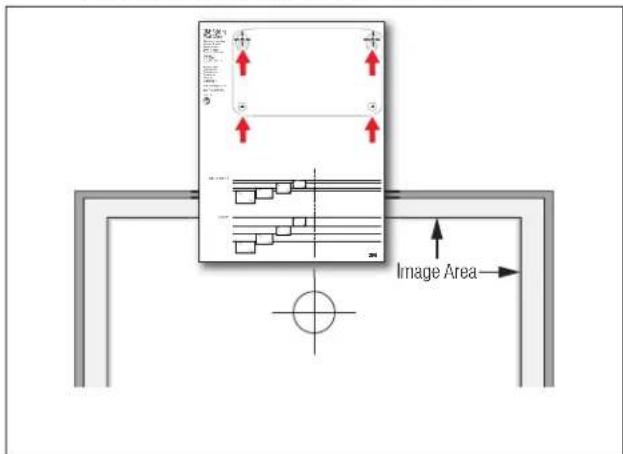
3M Folding Wall Mount SCPFWMSV2
5.3 Using the appropriate bit, drill 4 holes for the mounting lag bolt anchors. Install the short anchors in the upper holes, and the long anchors in the lower holes.
Note: Use a 1/2" masonry drill bit for solid concrete walls or a 3/16" drill bit for wood walls. Do not use anchors for wood walls, only use screws.
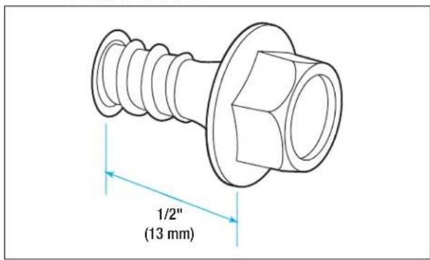
5.4 Using a 3 / 8 socket, install the 2 short (upper) mounting lag bolts, leaving 1 / 2 (13mm) of the screw protruding from the wall. DO NOT INSTALL THE LONG (LOWER) LAG BOLTS.

6.0 Attach to Wall
6.1 Hang the wall mount base on the mounting lag bolts. Using a 3/8 socket, tighten the mounting lag bolts securely.

3M^TM Folding Wall Mount SCPFWMSV2
6.2 Install the long mounting lag bolts through the leveling screws and tighten securely.
6.3 Skip to Step 9.
7.0 3M™ Wall Mount Bracket Installation (For Use With Concrete Block or Stud Walls)
7.1 Determine desired size and location of projected image and mark the location of the top and center of the image.
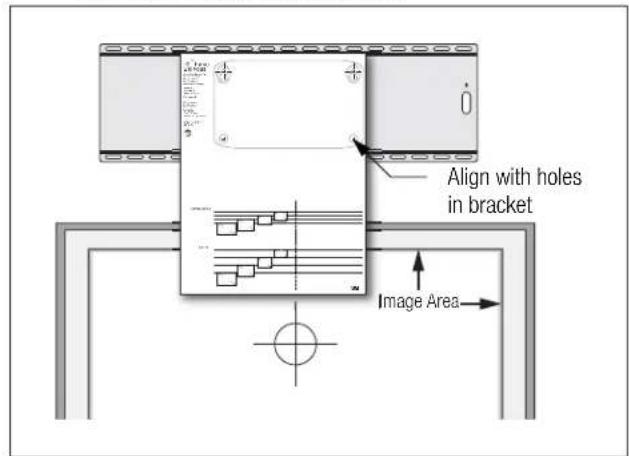
7.2 Align template with mounting holes in bracket and secure to bracket with tape.
7.3 Locate the "top of image" line of the template for the desired image size and then align "top of image" and "image center line" lines with the location of the desired image size. Mark positions for four mounting holes according to the next step.
7.4 Concrete block walls:
Mark the hole positions in the vertical joints between the concrete blocks and then using a 1 / 2'' (13 mm) bit, drill 4 holes 1 - 5 / 8'' (41 mm) deep into the vertical joints between the concrete blocks. Install 4 long anchors in the holes.
CAUTION
To reduce the risk associated with impact:
When installing the wall mount bracket, use only the 1 12 (38 mm) long lag anchors included with the bracket, not the 1" (25 mm) short lag anchors.
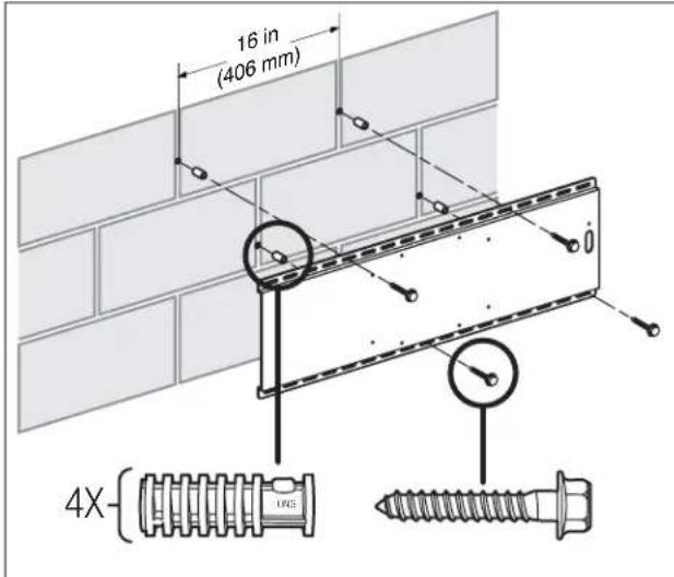
Stud walls:
Mark the holes at the center of the studs and then using a 3 / 16'' (5 mm) bit, drill 4 holes 1 - 1 / 2'' (38 mm) deep through the wall into the studs.
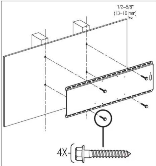
7.5 Using a 3/8'' socket, attach the bracket to the wall using 4 short mounting lag bolts.
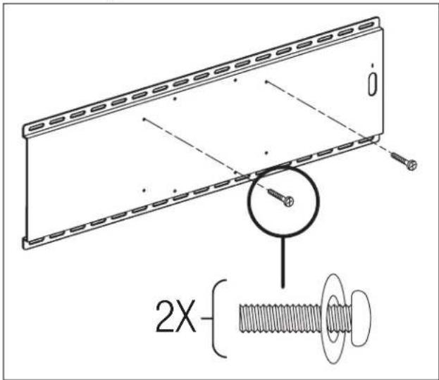
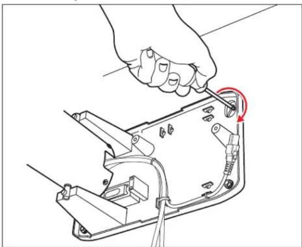
8.0 Attach Wall Mount Base to Bracket
8.1 Using a screwdriver, install the two short mounting screws with washers in the mounting bracket leaving 1/2 (13 mm) of the screw protruding from the bracket. Do not install the long (lower) mounting screws yet.
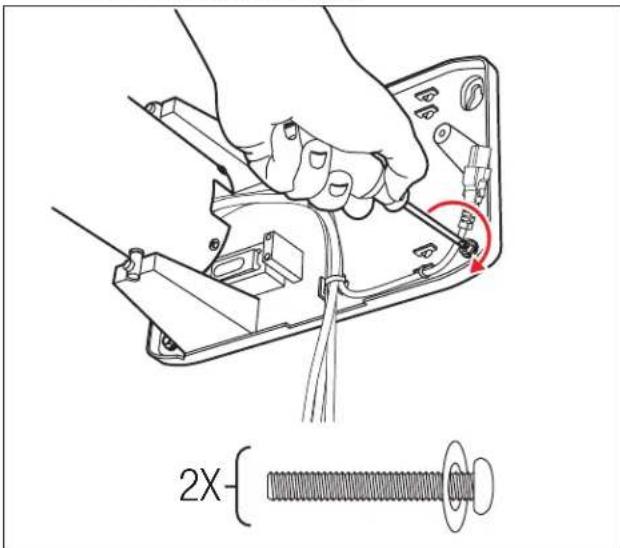
8.2 Hang the wall mount base on the mounting screws. Using a screwdriver, tighten the mounting screws securely.
8.3 Install the long mounting screws through the leveling screws and tighten securely.
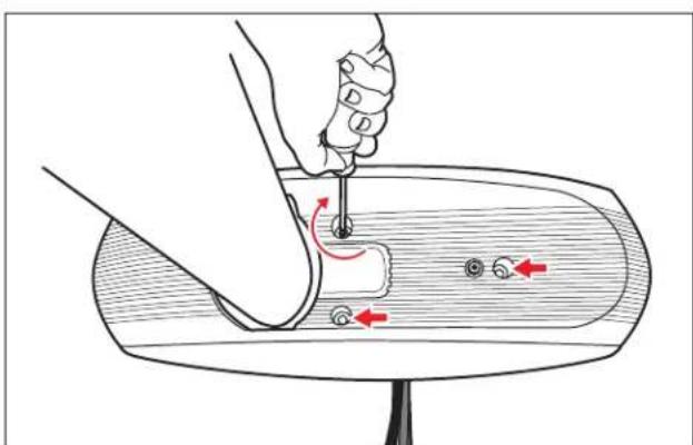
9.0 Install Security Kit (Optional)
9.1 Attach the optional security cable by either locking it to the mounting bracket security slot (1), looping it through the mounting bracket (2) or looping it through the screw-mount anchor point (3).
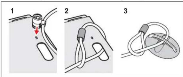
Note: If using the screw-mount anchor point, secure the anchor point before attaching the cable.
9.2 Feed the security lock cable through the arm. Secure about 6 inches (150mm) from the end of the existing cable bundle using a cable tie.
3M^TM Folding Wall Mount SCPFWMSV2
9.3 Route the security cable alongside the bundled cables and attach using cable ties.
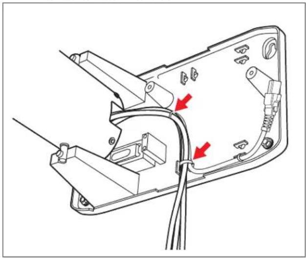
10.0 Connect Power Extension Cable
10.1 Connect the power extension cable as shown. Secure with cable ties.
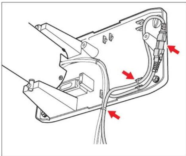
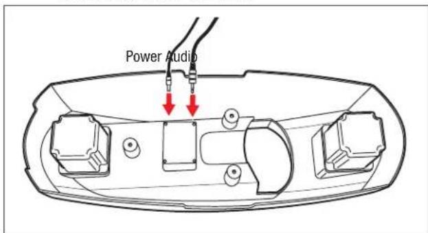
11.0 Connect Audio Cables (SCPFWMSV2 only)
11.1 Connect the power and audio cables to the connections inside the cover.
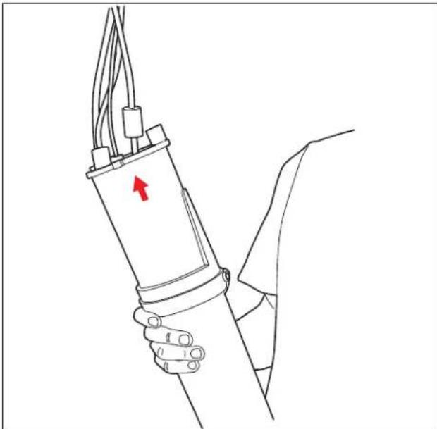
11.2 Slide the cover over the arm. Attach the power and audio cables to the existing cable bundle using a cable tie. Leave 10-12" (250-300 mm) slack cable.
12.0 Attach Cover
12.1 Attach the cover to the base.
13.0 Attach Projector
13.1 Using two screws and the thumbscrew, attach the mounting bracket to the end of the arm extension as shown.
13.2 Attach the projector to the mounting bracket with three screws.
Note: Some models will require two washers per screw to ensure a tight fit.
14.0 Assemble Arm Extension
14.1 Lift the assembly and feed the bundled cables through the open end of the arm extension.
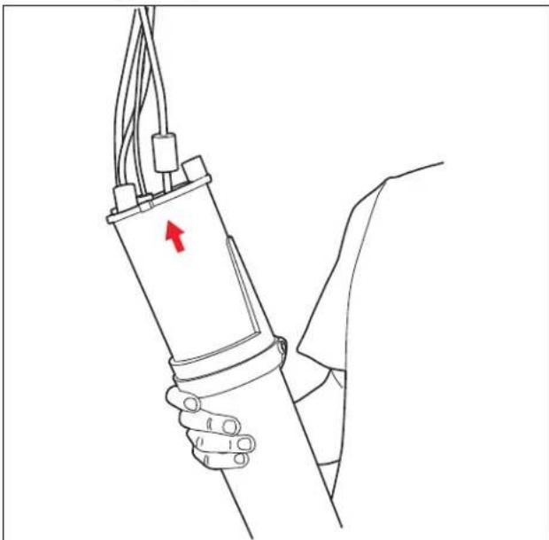
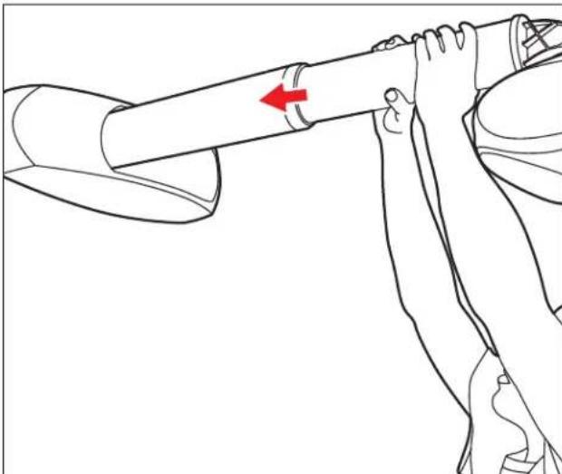
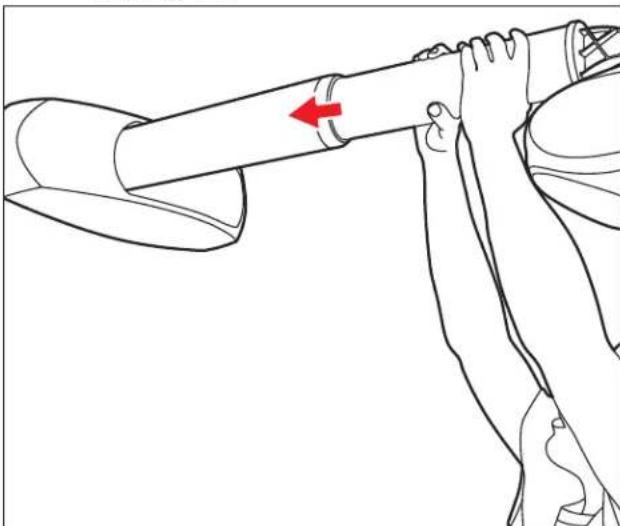
14.2 Insert the arm extension into the arm as shown.
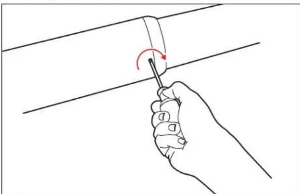
14.3 Install the 2 screws into the arm retainer.
3M Folding Wall Mount SCPFWMSV2
14.4 Pull the cable bundle through the hole at the end of the arm extension.
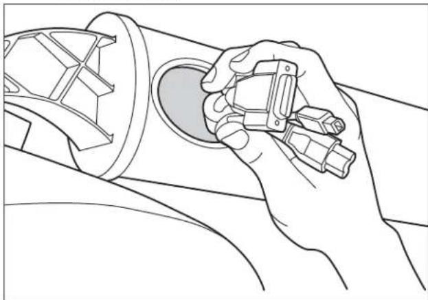
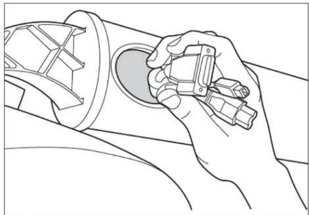
14.5 Connect the cables to the projector according to the Quick Start Guide.
14.6 Attach the optional security cable to the projector.
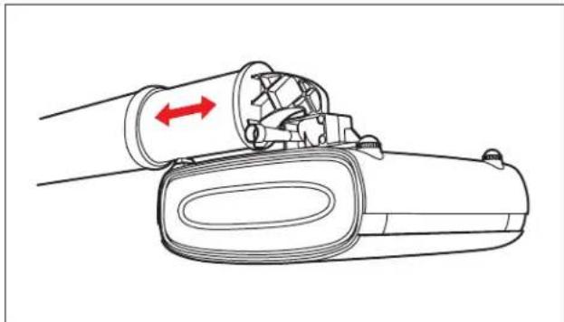
15.0 Align Projector
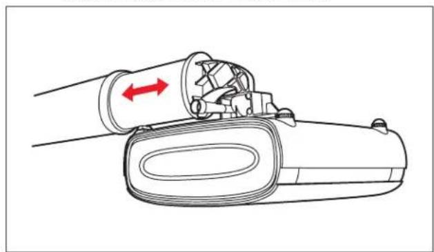
15.1 Power on unit and change image size by adjusting the arm extension in or out.
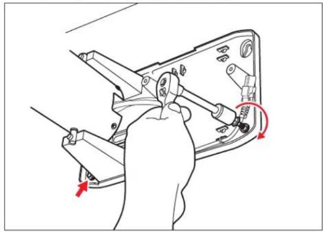
15.2 Adjust projector aim by loosening the thumb screw.
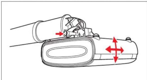
15.3 Adjust vertical image position by removing the cover, loosening the lower mounting lag bolts or mounting screws, and adjusting the leveling screws. Tighten the lower mounting lag bolts or screws when finished, and replace the cover.
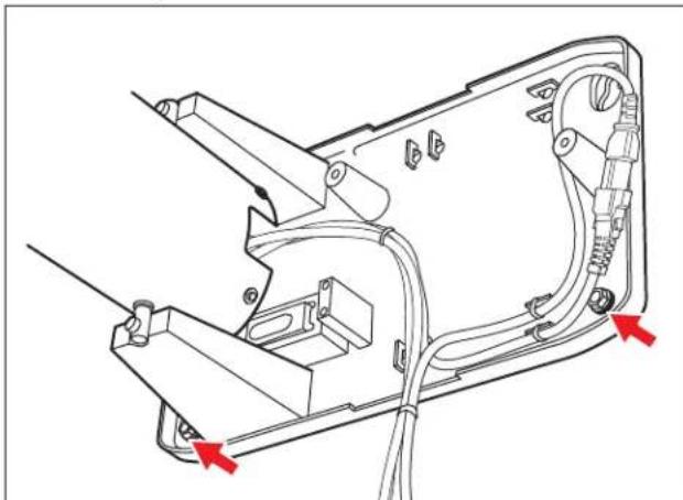
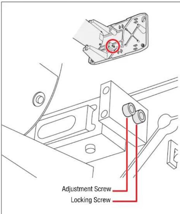
15.4 To adjust horizontal image position:
- Remove the cover.
- Loosen the adjustment and locking screws.
- Move the arm left or right to the desired position.
- Tighten the adjustment and locking screws to secure the arm in the new position.
- Replace the cover when finished.
3M is a trademark of 3M Company.
Important Notice
All statements, technical information, and recommendations related to 3M's products are based on information believed to be reliable, but the accuracy or completeness is not guaranteed. Before using this product, you must evaluate it and determine if it is suitable for your intended application. You assume all risks and liability associated with such use. Any statements related to the product which are not contained in 3M's current publications, or any contrary statements contained on your purchase order shall have no force or effect unless expressly agreed upon, in writing, by an authorized officer of 3M.
Warranty; Limited Remedy; Limited Liability.
3M warrants that when the 3M Product is used according to 3M's Intended Use Statement (www.3M.com/meetings), it will perform satisfactorily for the warranted durability period as stated in the applicable 3M Product Manual in effect at the time of purchase. The warranties stated in the applicable 3M Product Manuals are exclusive and are made in place of any and all express or implied warranties or conditions, including any implied warranty of merchantability or fitness for a particular purpose, or any industry practice or custom or trade usage.
3M
Projector Systems
6801 River Place Blvd.
Austin, TX 78726
8003281371
www.3M.com/meetings
Please Recycle. Printed in USA.
3M 2009. All Rights Reserved.
78-6971-1458-1-B
Montage mural repliable 3 M^TM SCPFWMSV2
Montage mural repliable 3M^p SCPFWMV2 ct SCPFWMSV2
DANS LE MANUEL DU PRODUIT 3M APPROPRIÉ OU LA DÉclaration D'USAGE PRÉVUE PAR 3M ANNULERA TOUTES LES GARANTIES ET LES RECOURS LIMITÉS. EN DEHORS DES CAS SPECIFIÉS DANS LE MANUEL APPLICABLE AU PRODUIT 3M, 3M DÉCLINE TOUTE RESPONSABILITÉ QUANT AUX DOMMAGES INDIRECTS, ACCIDENTELS, SPECIFIÉS OU SUBSEQUENTS (INCLUS, MAIS NON LIMITÉ À, PERTE DE PROFITS, DE REVENUS OU D'ACTIVITE) RÉSULTANT OU ÉTANT, DE QUELQUE FAÇON QUE CE SOIT, LIÉ À LA PERFORMANCE, L'UTILISATION, OU L'IMPOSSIBILITÉ D'UTILISER UN PRODUIT 3M QUEL QUIL SOIT. La présente limitation s'applique qu'elle que soit la théorie juridique sous laquelle les dommages sont revendiqués.
Montage mural repliable 3M^pc SCPFWMV2 ct SCPFWMSV2
Montage mural repliable 3M^pc SCPFWMV2 ct SCPFWMSV2
Montage mural repliable 3M^*4 SCPFWMV2 et SCPFWMSV2
6801 River Place Blvd.
Austin, TX 78726
8003281371
www.3M.com/meetings
6801 River Place Blvd.
Austin, TX 78726
8003281371
www.3M.com/meetings
2.0 Optional Accessories
Soporte del montaje mural 3M^TM (78-6969-9962-8)
Kit de seguridad 3M^TM (78-6969-9961-0)
3.0 Retirar la Tapa
6801 River Place Blvd.
Austin, TX 78726
8003281371
www.3M.com/meetings
6801 River Place Blvd.
Austin, TX 78726
8003281371
www.3M.com/meetings
3M™ Folding Wall Mount SCPFWMSV2
3M 3M 3M 3M 3M 3M 3M 3M 3M 3M 3M 3M 3M 3M 3M 3M 3M 3M 3M 3M 3M 3M 3M 3M 3M 3M 3M 3M 3M 3M 3M 3M 3M 3M 20000000000000000000000000000000000000000000000000000000000000000000000000000000000000
报中,
3M的说期地,主则在大和备山
6x KeiIeTb TaII(Cable ties)s
3xM6*25nss(t#
2x1-1/2"LaGbBolr(LagBolt)
2 × 1 / 2 "LaGhOgHcIe(LagAnchor)
2x 1-1/2" LaGoIgEer (Lag Anchor)
SCPFWMSV2 正常
1.8 mPC OukiO Kei
3mPCOukiOKei
S形封印式
SFlKrKefRnRnRnRnRnRnRnRnRnRnRnRnRnRnRnRnRnRnRnRnRnRnRnRnRnRnRnRnRnRnRnRnRnRnRnRnRnRnRnRnRnRnRnRnRnRnRnRnRnRnR
EU中国)国的国(E/国
3M° Folding Wall Mount SCPFWMV2 1 SCPFWMSV2
5.3 42
: 1/2113161131131131131131131131
5.4 3/8inTStKToJsUHHe,BeAeHTnLaNAs1/2InT (13mm)TtHnOg22oEeRnBt(S)TtHtHtHtHtHtHtHtHtHtHtHtHtHtHtHtHtHtHtHtHtHtHtHtHtHtHtHtHtHtHtHtHtHtHtHtHtHtHtHtHtHtHtHtHtHtHtHtHtHtHt H
6.0
3M" Folding Wall Mount SCPFWMV2 1 SCPFWMSV2
7.5 3/8inT sKtJ tH 4Ae 4nE HnE nHnE RnE
8.0 月云运电贝I斯来
3M" Folding Wall Mount SCPFWMV2 1 SCPFWMSV2
14.0 amm (arm extension)
14.1 电电电电电电电电电电电电电电电电电电电电电电电电电电电电电电电电电电电电电电电电电电电电电电电电电电电电电电电电电电电电电电电电电电电电电电电电电电电电电电电电电电电电电电电电电电电电电电电电电电电电
14.2 这和在里尔斯的上以
3M" Folding Wall Mount SCPFWMV2 !SCPFWMSV2
14.3 1
14.4 1
14.5 用S卡德自I德上如拉凯贝将扎罗默勒
14.6 皇
15.0 五元整数列
15.1 1
15.2 生成S克降为普阿托瓦罗到的

6801 River Place Blvd.
Austin, TX 78726
8003281371
www.3M.com/meetings
查音完音。
© 3M 2009. 法院社号
78-6971-1458-1-B
3 M^TM 折叠式壁挂
SCPFWMSV2
6801 River Place Blvd.
Austin, TX 78726
8003281371
www.3M.com/meetings
請回收。列印於美國。
6801 River Place Blvd.
Austin, TX 78726
8003281371
www.3M.com/meetings
请回收。印制于美国。
© 3M 2009. 保留所有权利。
78-6971-1458-1-B
6801 River Place Blvd.
Austin, TX 78726
8003281371
www.3M.com/meetings
拉沙尔儿を願いしま。米国に印刷。

- 3M™ Folding Wall Mount SCPFWMSV2
- Warranty; Limited Remedy; Limited Liability
- THE WARRANTY STATED ABOVE ARE EXCLUSIVE AND ARE MADE IN PLACE OF ANY AND ALL WARRANTY, EXPRESS OR IMPLIED WARRANTYS OR CONDITIONS, INCLUDING ANY IMPLIED WARRANTY OF MERCHANTABILITY OR FITNESS FOR A PARTICULAR PURPOSE, OR ANY INDUSTRY PRACTICE OR CUSTOM OR TRADE USAGE.
- What 3M Will Do To Correct Problems:
- Safety Instructions
- Intended Use
- Explanation of Signal Word Consequences
- Summary of device labels containing safety information
- WARNING
- To reduce the risk associated with all applicable hazards:
- To reduce the risk associated with choking:
- To reduce the risk associated with impact:
- To reduce the risk associated with hazardous voltage:
- To reduce the risk associated with fire:
- CAUTION
- To reduce the risk associated with pinch points:
- To reduce the risk associated with lifting:
- SAVE THESE INSTRUCTIONS
- Kit Contents
- SCPFWMSV2 Only
- Optional Accessories
- Remove the Cover
- Route Cables
- Solid Wall Installation
- Attach to Wall
- 3M™ Wall Mount Bracket Installation (For Use With Concrete Block or Stud Walls)
- Concrete block walls:
- Stud walls:
- Attach Wall Mount Base to Bracket
- Install Security Kit (Optional)
- Connect Power Extension Cable
- Connect Audio Cables (SCPFWMSV2 only)
- Attach Cover
- Attach Projector
- Assemble Arm Extension
- Align Projector
- Important Notice
- Warranty; Limited Remedy; Limited Liability.
- 3M
- Projector Systems
- Montage mural repliable 3 MTM SCPFWMSV2
- Retirar la Tapa
- 3M的说期地,主则在大和备山
- SCPFWMSV2 正常
- 6.0
- 月云运电贝I斯来
- amm (arm extension)
- 五元整数列
- MTM 折叠式壁挂
- SCPFWMSV2
Brand : 3M
Model : SCPFWMSV2
Category : Flat screen mount