SMP152 - Mixer Omnitronic - Free user manual and instructions
Find the device manual for free SMP152 Omnitronic in PDF.

User questions about SMP152 Omnitronic
0 question about this device. Answer the ones you know or ask your own.
Ask a new question about this device
Download the instructions for your Mixer in PDF format for free! Find your manual SMP152 - Omnitronic and take your electronic device back in hand. On this page are published all the documents necessary for the use of your device. SMP152 by Omnitronic.
USER MANUAL SMP152 Omnitronic
natural_image
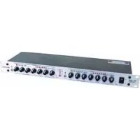
Front view of a SMP-152 audio amplifier drive with multiple knobs and control knobs (no visible text or labels beyond branding)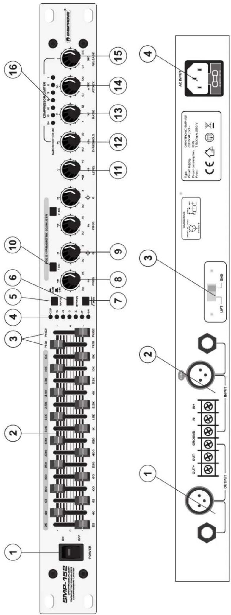
text_image
AC INPUT 4 INT 2 OUTPUT 3 INPUT 4 OUT+ OUT- SROUND INI INI 2 SQUAD NO INI 1 OUTPUT 16 SMIP-152 POWER ON 25 40 63 100 150 250 400 630 10X 19X 25X 40X 63X 10X 19X 25X 40X 63X 10X 19X 25X 40X 63X 10X 19X 25X 40X 63X 10X 19X 25X 40X 63X 10X 19X 25X 40X 63 X 4 INT 2 OUTPUT 3 SMIP-152 1 2 3 4 5 6 7 8 9 10 11 12 13 14 15 16 COMPRESSION LIMITER PRETOK RACK ATICK SYNC RATIO THRESHOLD LEVEL RAGD RPGD FREQD FREQD FREQD FREQD FREQD FREQD FREQD FREQD FREQD FREQD FREQD FREQD FREQD FREQD FREQD FREQD FREQD FREQD FREQD FREQD FREQD FREQD FREQD FREQD FREQD FSEQ DRYMS FRQDS FRQDS FRQDS FRQDS FRQDS FRQDS FRQDS FRQDS FRQDS FRQDS FRQDS FRQDS FRQDS FRQDS FRQDS FRQDS FRQDS FRQDS FRQDSMULTI-LANGUAGE-INSTRUCTIONS
CLEANING AND MAINTENANCE 21
TECHNICAL SPECIFICATIONS....22
Français
NTRODUCTION 23
INSTRUCTIONS DE SÉCURITÉ 23
EMPLOI SELON LES PRESCRIPTIONS 25
DESCRIPTION DE L'APPAREIL 25
INSTALLATION 25
MISE EN MARCHE 26
QUELQUES CONSEILS AUX DÉBUTANTS 26
MANIEMENT 27
NETTOYAGE ET MAINTENANCE 29
CARACTÉRISTIQUES TECHNIQUES 30
line
| t | OUTPUT | | ---- | ------ | | 0 | 10dB | | 2 | 8dB | | 4 | 2dB | | 6 | 10dB |Stage Monitor Processor
CAUTION!
Keep this device away from rain and moisture! Unplug mains lead before opening the housing!
For your own safety, please read this user manual carefully before you initial start-up.
Every person involved with the installation, operation and maintenance of this device has to
- be qualified
- follow the instructions of this manual
- consider this manual to be part of the total product
- keep this manual for the entire service life of the product
- pass this manual on to every further owner or user of the product
- download the latest version of the user manual from the Internet
INTRODUCTION
Thank you for having chosen an OMNITRONIC SMP-152. If you follow the instructions given in this manual, we are sure that you will enjoy this device for a long period of time.
Unpack your SMP-152.
Features
Professional monitor processor
- Parametric 2-band equalizer, compressor, limiter
• 15 graphic bands - For inserting into the mono-monitor-way
- 2 clipping frequencies can be actively adjusted to the correct level
- Via the EQ range selector, the display can be switched from ± 6 dB to ± 15 dB
- EQ-1/2 fader
- The overall output-level can be adjusted via the level-control
• LED-displays for all important functions - Inputs and outputs via 6.3" jack sockets, XLR-sockets and screw terminals
• 19" rack-mounting possible
SAFETY INSTRUCTIONS

CAUTION!
Be careful with your operations. With a dangerous voltage you can suffer a dangerous electric shock when touching the wires!
This device has left our premises in absolutely perfect condition. In order to maintain this condition and to ensure a safe operation, it is absolutely necessary for the user to follow the safety instructions and warning notes written in this user manual.

Important:
Damages caused by the disregard of this user manual are not subject to warranty. The dealer will not accept liability for any resulting defects or problems.
If the device has been exposed to drastic temperature fluctuation (e.g. after transportation), do not switch it on immediately. The arising condensation water might damage your device. Leave the device switched off until it has reached room temperature.
Please make sure that there are no obvious transport damages. Should you notice any damages on the A/C connection cable or on the casing, do not take the device into operation and immediately consult your local dealer.
This device falls under protection-class I. The power plug must only be plugged into a protection class I outlet. The voltage and frequency must exactly be the same as stated on the device. Wrong voltages or power outlets can lead to the destruction of the device and to mortal electrical shock.
Always plug in the power plug least. The power plug must always be inserted without force. Make sure that the plug is tightly connected with the outlet.
Never let the power-cord come into contact with other cables! Handle the power-cord and all connections with the mains with particular caution! Never touch them with wet hands, as this could lead to mortal electrical shock.
Never modify, bend, strain mechanically, put pressure on, pull or heat up the power cord. Never operate next to sources of heat or cold. Disregard can lead to power cord damages, fire or mortal electrical shock.
The cable insert or the female part in the device must never be strained. There must always be sufficient cable to the device. Otherwise, the cable may be damaged which may lead to mortal damage.
Make sure that the power-cord is never crimped or damaged by sharp edges. Check the device and the power-cord from time to time.
If extension cords are used, make sure that the core diameter is sufficient for the required power consumption of the device. All warnings concerning the power cords are also valid for possible extension cords.
Always disconnect from the mains, when the device is not in use or before cleaning it. Only handle the power-cord by the plug. Never pull out the plug by tugging the power-cord. Otherwise, the cable or plug can be damaged leading to mortal electrical shock. If the power plug or the power switch is not accessible, the device must be disconnected via the mains.
If the power plug or the device is dusty, the device must be taken out of operation, disconnected and then be cleaned with a dry cloth. Dust can reduce the insulation which may lead to mortal electrical shock. More severe dirt in and at the device should only be removed by a specialist.
There must never enter any liquid into power outlets, extension cords or any holes in the housing of the device. If you suppose that also a minimal amount of liquid may have entered the device, it must immediately be disconnected. This is also valid, if the device was exposed to high humidity. Also if the device is still
English
running, the device must be checked by a specialist if the liquid has reduced any insulation. Reduced insulation can cause mortal electrical shock.
There must never be any objects entering into the device. This is especially valid for metal parts. If any metal parts like staples or coarse metal chips enter into the device, the device must be taken out of operation and disconnected immediately. Malfunction or short-circuits caused by metal parts may cause mortal injuries.
Before the device is switched on all faders and volume controls have to be set to "0" or "min" position.
CAUTION: Turn the amplifier on last and off first!
Please note that damages caused by manual modifications on the device or unauthorized operation by unqualified persons are not subject to warranty.
Keep away children and amateurs!

HEALTH HAZARD!
By operating an amplifying system, you can produce excessive sound pressure levels that may lead to permanent hearing loss.
There are no serviceable parts inside the device. Maintenance and service operations are only to be carried out by authorized dealers.
OPERATING DETERMINATIONS
This device is a professional processor for modifying and compressing incoming audio-signals. This product is allowed to be operated with an alternating current of 230 V, 50 Hz and was designed for indoor use only.
Do not shake the device. Avoid brute force when installing or operating the device.
When choosing the installation-spot, please make sure that the device is not exposed to extreme heat, moisture or dust. There should not be any cables lying around. You endanger your own and the safety of others!
Do not operate the device in extremely hot (more than 35^ C) or extremely cold (less than 5^ C) surroundings. Keep away from direct insulation (particularly in cars) and heaters.
Operate the device only after having familiarized with its functions. Do not permit operation by persons not qualified for operating the device. Most damages are the result of unprofessional operation!
Never use solvents or aggressive detergents in order to clean the device! Rather use a soft and damp cloth.
Please use the original packaging if the device is to be transported.
Please consider that unauthorized modifications on the device are forbidden due to safety reasons!
Never remove the serial barcode from the device as this would make the guarantee void.
If this device will be operated in any way different to the one described in this manual, the product may suffer damages and the guarantee becomes void. Furthermore, any other operation may lead to dangers like short-circuit, burns, electric shock, etc.
DESCRIPTION
The OMNITRONIC Processor SMP-152 is designed for professional application. The inputs and outputs are located on the rear panel, the control elements on the front panel.
English
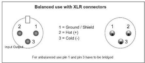
Occupation balanced XLR-connection:
text_image
Balanced use with XLR connectors Input Output... 1 = Ground / Shield 2 = Hot (+) 3 = Cold (-) For unbalanced use pin 1 and pin 3 have to be bridgedOccupation jack plug:

text_image
Unbalanced use of mono 1/4" jack plugs Tip = Signal (+) Sleeve = Ground / Shield Tip Sleeve Strain relief clamp Balanced use of stereo 1/4" jack plugs Tip = hot (+) Ring = cold (-) Sleeve = Ground / Shield Tip Ring Sleeve Strain relief clamp For connection of balanced and unbalanced plugs, ring and sleeve have to be bridged at the stereo plug.The occupation of the screw connectors is as follows:
Connection 1 = Signal +
Connection 2 = Signal -
Connection 3 = Shield
INSTALLATION
RACK MOUNTING
The processor is built for 19" racks/483 mm. The minimum mounting depth is 220 mm. The height is 44 mm. You can fix the processor with four screws M6 in the rack.
When mounting the processor into a rack, please make sure that there is a proper air circulation.
Please make sure that there is enough space around the device so that the heated air can be passed on. The rack should be provided with a cooling fan.
Be careful when mounting the processor into the rack. Put the heaviest devices into the lower part of the rack. Be aware that fastening the processor with four screws on the front panel is not enough. In order to ensure safety, additional fastening by using ground and side bars is necessary.
If racks are to be transported or used for mobile use, additionally fasten the devices by connecting the rear brackets with the side or ground bars of the rack. In this way, the processor cannot be pushed backwards.
The front panel alone is not designed to absorb acceleration forces occurring during transportation.
INPUTS
A good cable run improves the sound quality remarkably. Input cables should be short and direct, since high frequencies will be mostly be absorbed if the cables are unnecessarily long. Besides that a longer cable may lead to humming and noise trouble. If long cable runs are unavoidable, you should use balanced cables.
The inputs of your OMNITRONIC SMP-152 are equipped with XLR and 14 " jack-sockets and screw connectors.
English
OUTPUTS
The high damping factor of your processor supplies a clear sound reproduction. Unnecessarily long and thin cables will influence the damping factor and thus the low frequencies in a negative way. In order to safeguard good sound quality, the damping factor should lie around 50.
The outputs of your OMNITRONIC SMP-152 are equipped with 6.3 mm jacks, XLR and screw connectors.
CONNECTION TO THE MAINS
Connect the OMNITRONIC SMP-152 only after having made sure that the right voltage (230 V) is available. This device features a T 0.5 A, 250 V fuse.
Connect the device to the mains with the enclosed power supply cable.
The occupation of the connection-cables is as follows:
| Cable Pin International | |
| Brown Live L | |
| Blue Neutral N | |
| Yellow/Green Earth | [WSCD] |
The earth has to be connected!
If the device will be directly connected with the local power supply network, a disconnection switch with a minimum opening of 3 mm at every pole has to be included in the permanent electrical installation.
The device must only be connected with an electric installation carried out in compliance with the IEC-standards. The electric installation must be equipped with a Residual Current Device (RCD) with a maximum fault current of 30 mA.
STARTING UP
Make sure to power-up before your power amplifier is turned in order to avoid loud transients which could damage your speakers or annoy your audience.
STARTERS' GUIDE TO EQUALIZERS
At first glance, a graphic equalizer may appear to be a complicated device, but actually, in theory and operation, a graphic equalizer is a very simple device. Most people are familiar with bass and treble tone controls. These controls work by dividing the audio signal into two frequency bands - the low frequencies and the high frequencies. The bass knob, then, effectively becomes a volume control for the lows and the treble knob gives us volume control over the highs.
"Hz" stands for "Hertz". "KHz" stands for "thousands of Hertz". These are measures of sound-cycles per second. You see, sound waves are measured by the number of cycles or vibrations they make in one second. Very low-pitched sounds like bass guitars have far fewer cycles per second than high-pitched sounds like cymbals. So, if you want to increase the volume of the cymbals in a recording without affecting the volume of the bass guitar, use the treble control.
The cymbals occupy only a very small band of frequencies within those controlled by the treble control. Also included in the range of the treble control are vocal sounds. They occupy a similarly narrow band of frequencies somewhat lower than the cymbals. A treble control alone does not offer enough flexibility of control to allow us to increase the volume of the cymbals without also increasing
the volume of the vocals. What is needed is a type of control that divides the audio signal, not into two bands, but as many bands as possible. This would allow us almost unlimited flexibility of control over the tone "colors" in our audio program.
That's exactly what a graphic equalizer allows us to do. It gives us precise control over the volume of manynarrow frequency bands, each of which can add (or subtract) their own particular tone "color" to our overall sound.
In the recording studio and on stage, graphic equalizers are generally used for three distinct purposes:
1.) ROOM EQUALIZATION: Every room adds its own "character" to the sound of music played in it because of the way the walls, floors, ceilings, furnishings and people absorb or reflect the sound waves. Every room
English
boosts some frequencies and attenuates others in this way. So graphic equalizers are used, in this context, to compensate for the "damage" done to the sound by the room itself.
2.) FEEDBACK CONTROL: Without a graphic equalizer, it is quite difficult to stop feedback (that piercing, whistling sound that happens when microphones pick-up and reamplify the sound from the speakers). A graphic equalizer can zero in on the offending frequency and reduce it, leaving the rest of the music unchanged.
3.) CREATIVE RECORDING: Graphic equalizers are routinely used to make certain sounds "brighter" or "fuller" or even radically different, depending on the creative whims of the operator. A voice can be made to sound as though it's coming through a telephone line, for example. An acoustic guitar can be given a metallic sparkle. A kick drum can get more "snap". It may be a cliché, but it's true: With a graphic equalizer, you are only limited by your own imagination!
OPERATION
Front panel
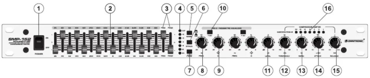
text_image
SMP-152 POWER ON 25 40 62 800 960 250 400 620 8 150 2.5K 4K 6.2K 10K 16K 7001 7002 2 2 3 4 5 6 10 7 8 9 11 12 13 14 15 COMPRESSOR/STARTOR CONTRIBUTION OF RATIO ATTACK RELEASE OWNTATIONIC1. POWER Switch
Turns power to the processor on and off. Be sure to power-up before your power amplifier is turned on to avoid loud transients which could damage your speakers or annoy your audience.
EQUALIZER SECTION
2. FREQUENCY Faders
Move these sliders upwards to boost a specific frequency. Move them downwards cut (decrease) them. When moving these controls past zero, you will feel the center-detent (notch) in the control which makes it very easy to find zero in a hurry, or even in the dark.
3. PEQ Faders 1 & 2
Move these sliders upwards to boost a specific frequency. Move them downwards cut (decrease) them. When moving these controls past zero, you will feel the center-detent (notch) in the control which makes it very easy to find zero in a hurry, or even in the dark.
4. LED LEVEL Meter
Indicates the level reduction in dB.
5. PROCESSOR RANGE Selector
One of the reasons to use a graphic processor is that the frequency sliders themselves form a graphic depiction of the frequency response curve you have set. But if your settings are very subtle, the "graph" becomes difficult to set and see. If you encounter this difficulty, simply push this Range Selector Switch. You can reduce the maximum boost/cut range of the frequency sliders from 15 dB to 6 dB and make your adjustments, taking advantage of the greater fader travel necessary to get the same amount of hoost or cut.
6. EQ BYPASS Selector
This switch allows instant comparison of the original sound with the equalized sound.
7. LOW CUT Selector
This switch allows you to cut down unwanted low frequencies.
English
COMPRESSOR / LIMITER SECTION
The task of Compressors and Limiters is to reduce the dynamic range of the program material and to control the overall level. It prevents signals from exceeding a given threshold level. The extent of the resulting dynamic level is dependent on Threshold, Attack, Release and Ration settings.
8. FREQ Control 1 & 2
Adjust a frequency between 20 and 2 K.
9. Q (Quality) Control
Adjust the bandwidth (Q-factor) between 30 and 3 Q.
10. FX 10 Button 1 & 2
Press this button to multiply the FREQ frequency range with the factor 10.
11. LEVEL Control
To adjust the output level. If a frequency range is highly boosted, the output level needs to be reduced via the level-control in order to avoid amplifier distortion.
12. THRESHOLD Control
The Threshold control sets the threshold point for the Compressor section. It has a range of -40 to +20 dB.
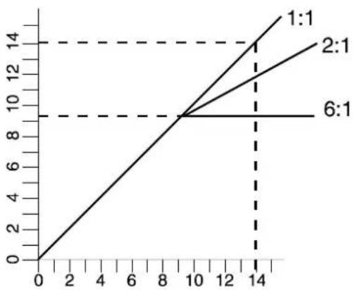
13. RATIO Control
This control determines the ratio between the input and output level for all signals exceeding the threshold point by more than 10 dB. The control range can be adjusted from 1:1 to :1. A setting of 1:1 leads to no compression, turning the control clockwise makes the sound increasingly dense. A setting of :1 corresponds to a limiter setting.
FIGURE A explains the comparison of compressed signals responding to various Ratio settings.
line
| x | 1:1 | 2:1 | 6:1 | |----|------|------|------| | 0 | 0 | 0 | 0 | | 10 | 10 | 10 | 10 | | 14 | 14 | 13 | 9 |14. ATTACK Control
This control determines the rate by which the compressor responds to the signal which exceeds the threshold. This control can be adjusted from 0.1 ms to 100 ms. Use short Attack times for percussion and slower times soft inaudible compression.
15. RELEASE Control
This control determines the rate that the compressor returns to unity again after falling below the threshold level. This control can be adjusted from 0.1 to 2.5 seconds. Use short times for fast recovery and maximum output and use longer times to avoid pumping.
The following diagram shows how the ATTACK/RELEASE works. Different time settings will create different effects
English
Example: INPUT LEVEL 10 dB at 4 dB compression
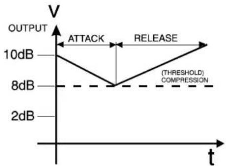
line
| t | OUTPUT | | ---- | ------ | | 0 | 10dB | | 2 | 2dB | | 4 | 8dB | | 6 | 10dB | | 8 | 8dB | | 10 | 10dB |16. GAIN REDUCTION LED Meter
Displays the attenuation in dB.
Suggested Settings
| ATTACK RELEASE RATIO | |||
| Vocals Medium to Fast M | Medium to Slow 2:1 | to 4:1 | |
| Clicky Bass Fast Fast 4:1 or higher | |||
| Mushy Bass Medium to | Slow Medium to S | ow 4:1 | |
| Raging Electric Guitar | Fast Slow 4:1 or higher | ||
| Acoustic Guitar Medium to | Slow Medium to | Slow 4:1 | |
| Brassy Horns Fast Fast | 5:1 or higher | ||
| Drums (kick, snare) Fast | Fast 4:1 | ||
| Drums (cymbals) Fast | Slow 2:1 to 10:1 | ||
Rear panel

text_image
1 2 3 4 OUTPUT OUT+ GROUND IN+ INPUT UFT SND AC INPUT Type: OMINTROIC CMP E52 Power supply: 200 V AC 50 - Power consumption: 0 W T 500 mA 250 V CE AC INPUT-
INPUT-Sockets
-
OUTPUT-Sockets
-
GROUND LIFT-Switch
-
AC-Connection with Fuseholder
Used to plug the power-cord in.
CLEANING AND MAINTENANCE
DANGER TO LIFE!
Disconnect from mains before starting maintenance operation!
We recommend a frequent cleaning of the device. Please use a soft lint-free and moistened cloth. Never use alcohol or solvents!
English
There are no servicable parts inside the device except for the fuse. Maintenance and service operations are only to be carried out by authorized dealers.
Replacing the fuse
If the fine-wire fuse of the device fuses, only replace the fuse by a fuse of same type and rating.
Before replacing the fuse, unplug mains lead.
Procedure:
Step 1: Open the fuseholder on the rearpanel with a fitting screwdriver.
Step 2: Remove the old fuse from the fuseholder.
Step 3: Install the new fuse in the fuseholder.
Step 4: Replace the fuseholder in the housing.
Should you need any spare parts, please use genuine parts.
If the power supply cable of this device becomes damaged, it has to be replaced by a special power supply cable available at your dealer.
Should you have further questions, please contact your dealer.
TECHNICAL SPECIFICATIONS
| System specifications: | |
| Power supply: 230 V AC, 50 Hz ~ | |
| Power consumption: 10 W | |
| Fuse: T 0.5 A | |
| Audio inputs/outputs: XLR, jack, screw terminals | |
| Input impendance: 10/20 kOhms (unb./bal.) | |
| Output impendance: 300/150 kOhms (unb./bal.) | |
| Frequency response: 20 Hz - 20 kHz, ±3 dB | |
| S/N ratio: >95 dB, unweighted | |
| Crosstalk: >90 dB | |
| Distortion: < 0.01 % | |
| Frequencies: 25/40/63/100/160/250/400/630Hz/1k/1.6k/2.5k/4k/6.3k/10k/16 kHz | |
| Equalizer section: | |
| Frequency: variable (20 to 2 kHz) | |
| Q (Quality): | variable (30 to 3) |
| Control range: | ±6 dB or ±15 dB |
| Low Cut: | 30 Hz |
| Compressor section: | |
| Threshold: | variable (-40 to +22 dBu) |
| Ratio: | variable (1:1 to ∞:1) |
| Attack time: | variable (0.1 ms to 100 ms) |
| Release time: | variable (0.1 sec to 2.5 sec) |
| Output: | variable (-∞ to +6 dB) |
| Display: | |
| Gain Reduction: | VU Meter, 7 LEDs |
| Dimensions/Weight: | |
| Dimensions (WxDxH): | 483 x 210 x 44 mm |
| Weight: | 3 kg |
Please note: Every information is subject to change without prior notice. 06.09.2006 ©
MODE D'EMPLOI

OMNITRONIC

SMP-152
Stage Monitor Processor