
CL166 - Mixer Omnitronic - Free user manual and instructions
Find the device manual for free CL166 Omnitronic in PDF.
| Product Type | Dynamic Processor (Compressor / Gate) |
| Brand | Omnitronic |
| Model | CL166 |
| Category | Mixer |
| Power Supply | 230 V AC, 50 Hz, 10 W |
| Fuse | T 0.5 A, 250 V |
| Dimensions (W x D x H) | 483 x 147 x 46 mm |
| Weight | 2 kg |
| Audio Inputs / Outputs | XLR and 6.3 mm jack balanced |
| Input Impedance | 10 / 20 kOhm |
| Output Impedance | 300 / 150 kOhm |
| Frequency Response | 20 Hz - 20 kHz, ±3 dB |
| Signal-to-Noise Ratio | > 95 dB |
| Total Harmonic Distortion | 0.05 % |
| Gate Section - Threshold | -45 to +10 dBu |
| Gate Section - Release | 0.1 ms to 2 s |
| Compressor Section - Threshold | -40 to +22 dBu |
| Compressor Section - Ratio | 1:1 to ∞:1 |
| Compressor Section - Attack | 0.1 ms to 100 ms |
| Compressor Section - Release | 0.05 s to 2.5 s |
| Compressor Section - Output Level | -18 to +18 dB |
| Display | 7-LED VU meter (gain reduction and level) |
| Operating Modes | Stereo (Link) or Dual Mono |
| Bypass Function | Per channel, independent |
| Rack Mount | 19", minimum depth 160 mm |
| Operating Temperature | 5 °C to 35 °C |
| Maintenance | Soft damp cloth, no alcohol |
| Fuse Replacement | Identical type (T 0.5 A) |
| Repairs | By qualified technician only |
| Protection Class | I (mandatory grounding) |
Frequently Asked Questions - CL166 Omnitronic
User questions about CL166 Omnitronic
0 question about this device. Answer the ones you know or ask your own.
Ask a new question about this device
Download the instructions for your Mixer in PDF format for free! Find your manual CL166 - Omnitronic and take your electronic device back in hand. On this page are published all the documents necessary for the use of your device. CL166 by Omnitronic.
USER MANUAL CL166 Omnitronic
MULTI-LANGUAGE-INSTRUCTIONS
CLEANING AND MAINTENANCE 21
TECHNICAL SPECIFICATIONS.... 22
Français
INTRODUCTION 23
INSTRUCTIONS DE SÉCURITÉ 23
EMPLOI SELON LES PRESCRIPTIONS 25
DESCRIPTION DE L'APPAREIL 25
NETTOYAGE ET MAINTENANCE 29
CARACTÉRISTIQUES TECHNIQUES 30
line
| Time (t) | Output (V) | | -------- | ---------- | | 0 | 10dB | | 8 | 8dB | | >8 | 2dB |10. LEVEL-Regler
Keep this device away from rain and moisture! Unplug mains lead before opening the housing!
For your own safety, please read this user manual carefully before you initial start-up.
Every person involved with the installation, operation and maintenance of this device has to
- be qualified
- follow the instructions of this manual
- consider this manual to be part of the total product
- keep this manual for the entire service life of the product
- pass this manual on to every further owner or user of the product
- download the latest version of the user manual from the Internet
INTRODUCTION
Thank you for having chosen an OMNITRONIC CL-166. If you follow the instructions given in this manual, we are sure that you will enjoy this device for a long period of time.
Unpack your CL-166.
Features
Indispensable Stereo compressor-limiter
- 2 channels
- Switchable from stereo to mono operation
- Bypass switch allows instant comparison of the original sound with the equalized sound without changing any settings
- Every channel with threshold, attack, release, ratio, output-control
- Variable independent gate with threshold and release-control
- Large LEDs
- Only 1 U height
• Control of the vocal level of a singer with less microphone technique
• To round excessively filtered sounds - To even level oscillation of microphones or instruments
- Protects your sound system against override and destruction
• Recording from analogue to digital
SAFETY INSTRUCTIONS
CAUTION!
Be careful with your operations. With a dangerous voltage you can suffer a dangerous electric shock when touching the wires!
This device has left our premises in absolutely perfect condition. In order to maintain this condition and to ensure a safe operation, it is absolutely necessary for the user to follow the safety instructions and warning notes written in this user manual.

Important:
Damages caused by the disregard of this user manual are not subject to warranty. The dealer will not accept liability for any resulting defects or problems.
If the device has been exposed to drastic temperature fluctuation (e.g. after transportation), do not switch it on immediately. The arising condensation water might damage your device. Leave the device switched off until it has reached room temperature.
Please make sure that there are no obvious transport damages. Should you notice any damages on the A/C connection cable or on the casing, do not take the device into operation and immediately consult your local dealer.
This device falls under protection-class I. The power plug must only be plugged into a protection class I outlet. The voltage and frequency must exactly be the same as stated on the device. Wrong voltages or power outlets can lead to the destruction of the device and to mortal electrical shock.
Always plug in the power plug least. The power plug must always be inserted without force. Make sure that the plug is tightly connected with the outlet.
Never let the power-cord come into contact with other cables! Handle the power-cord and all connections with the mains with particular caution! Never touch them with wet hands, as this could lead to mortal electrical shock.
Never modify, bend, strain mechanically, put pressure on, pull or heat up the power cord. Never operate next to sources of heat or cold. Disregard can lead to power cord damages, fire or mortal electrical shock.
The cable insert or the female part in the device must never be strained. There must always be sufficient cable to the device. Otherwise, the cable may be damaged which may lead to mortal damage.
Make sure that the power-cord is never crimped or damaged by sharp edges. Check the device and the power-cord from time to time.
If extension cords are used, make sure that the core diameter is sufficient for the required power consumption of the device. All warnings concerning the power cords are also valid for possible extension cords.
Always disconnect from the mains, when the device is not in use or before cleaning it. Only handle the power-cord by the plug. Never pull out the plug by tugging the power-cord. Otherwise, the cable or plug can be damaged leading to mortal electrical shock. If the power plug or the power switch is not accessible, the device must be disconnected via the mains.
If the power plug or the device is dusty, the device must be taken out of operation, disconnected and then be cleaned with a dry cloth. Dust can reduce the insulation which may lead to mortal electrical shock. More severe dirt in and at the device should only be removed by a specialist.
There must never enter any liquid into power outlets, extension cords or any holes in the housing of the device. If you suppose that also a minimal amount of liquid may have entered the device, it must immediately be disconnected. This is also valid, if the device was exposed to high humidity. Also if the device is still
English
running, the device must be checked by a specialist if the liquid has reduced any insulation. Reduced insulation can cause mortal electrical shock.
There must never be any objects entering into the device. This is especially valid for metal parts. If any metal parts like staples or coarse metal chips enter into the device, the device must be taken out of operation and disconnected immediately. Malfunction or short-circuits caused by metal parts may cause mortal injuries.
Before the device is switched on all faders and volume controls have to be set to "0" or "min" position.
CAUTION: Turn the amplifier on last and off first!
Please note that damages caused by manual modifications on the device or unauthorized operation by unqualified persons are not subject to warranty.
Keep away children and amateurs!

HEALTH HAZARD!
By operating an amplifying system, you can produce excessive sound pressure levels that may lead to permanent hearing loss.
There are no serviceable parts inside the device. Maintenance and service operations are only to be carried out by authorized dealers.
OPERATING DETERMINATIONS
This device is a professional compressor for modifying and compressing incoming audio-signals. This product is allowed to be operated with an alternating current of 230 V, 50 Hz and was designed for indoor use only.
Do not shake the device. Avoid brute force when installing or operating the device.
When choosing the installation-spot, please make sure that the device is not exposed to extreme heat, moisture or dust. There should not be any cables lying around. You endanger your own and the safety of others!
Do not operate the device in extremely hot (more than 30^ C) or extremely cold (less than 5^ C) surroundings. Keep away from direct insulation (particularly in cars) and heaters.
Operate the device only after having familiarized with its functions. Do not permit operation by persons not qualified for operating the device. Most damages are the result of unprofessional operation!
Never use solvents or aggressive detergents in order to clean the device! Rather use a soft and damp cloth.
Please use the original packaging if the device is to be transported.
Please consider that unauthorized modifications on the device are forbidden due to safety reasons!
Never remove the serial barcode from the device as this would make the guarantee void.
If this device will be operated in any way different to the one described in this manual, the product may suffer damages and the guarantee becomes void. Furthermore, any other operation may lead to dangers like short-circuit, burns, electric shock, etc.
DESCRIPTION
The OMNITRONIC Compressor CL-166 is designed for professional application. The inputs and outputs are located on the rear panel, the control elements on the front panel.
English
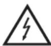
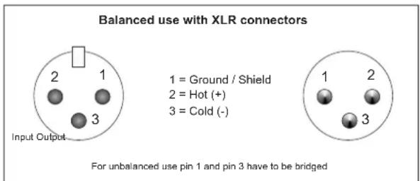
Occupation balanced XLR-connection:
Balanced use with XLR connectors
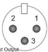
1 = Ground / Shield
2 = Hot (+)
3 = Cold (-)
For unbalanced use pin 1 and pin 3 have to be bridged
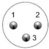
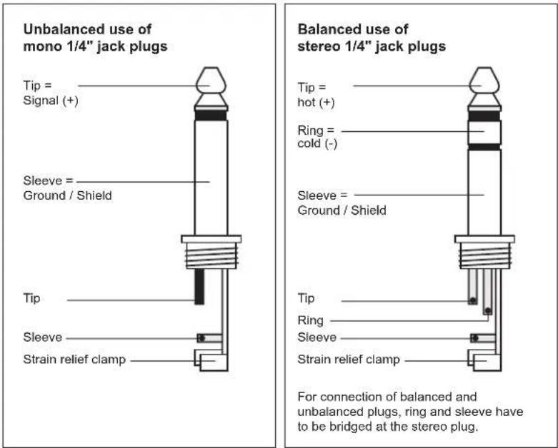
Occupation jack plug:
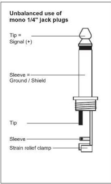
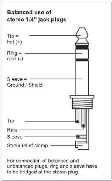
INPUTS
A good cable run improves the sound quality remarkably. Input cables should be short and direct, since high frequencies will be mostly be absorbed if the cables are unnecessarily long. Besides that a longer cable may lead to humming and noise trouble. If long cable runs are unavoidable, you should use balanced cables. The inputs of your OMNITRONIC CL-166 are equipped with XLR and 14 " jack-sockets.
OUTPUTS
The high damping factor of your compressor supplies a clear sound reproduction. Unnecessarily long and thin cables will influence the damping factor and thus the low frequencies in a negative way. In order to safeguard good sound quality, the damping factor should lie around 50. The outputs of your OMNITRONIC CL-166 are equipped with 6.3 mm jacks and XLR connectors.
CONNECTION TO THE MAINS
Connect the OMNITRONIC CL-166 only after having made sure that the right voltage (230 V) is available. This device features a T 0.5 A, 250 V fuse. Connect the device to the mains with the enclosed power supply cable.
The occupation of the connection-cables is as follows:
| Cable Pin International | ||
| Brown Live L | ||
| Blue Neutral N | ||
| Yellow/Green Earth | [85×8] | |
English
The earth has to be connected!
If the device will be directly connected with the local power supply network, a disconnection switch with a minimum opening of 3 mm at every pole has to be included in the permanent electrical installation.
The device must only be connected with an electric installation carried out in compliance with the IEC-standards. The electric installation must be equipped with a Residual Current Device (RCD) with a maximum fault current of 30 mA.
INSTALLATION
RACK MOUNTING
The compressor is built for 19" racks/483 mm. The minimum mounting depth is 160 mm. The height is 44 mm. You can fix the compressor with four screws M6 in the rack.
When mounting the compressor into a rack, please make sure that there is a proper air circulation.
Please make sure that there is enough space around the device so that the heated air can be passed on.
The rack should be provided with a cooling fan.
Be careful when mounting the compressor into the rack. Put the heaviest devices into the lower part of the rack. Be aware that fastening the compressor with four screws on the front panel is not enough. In order to ensure safety, additional fastening by using ground and side bars is necessary.
If racks are to be transported or used for mobile use, additionally fasten the devices by connecting the rear brackets with the side or ground bars of the rack. In this way, the compressor cannot be pushed backwards.
The front panel alone is not designed to absorb acceleration forces occurring during transportation.
STARTING UP
Make sure to power-up before your power amplifier is turned in order to avoid loud transients which could damage your speakers or annoy your audience.
OPERATION
Front panel
Channel A and Channel B are identical.
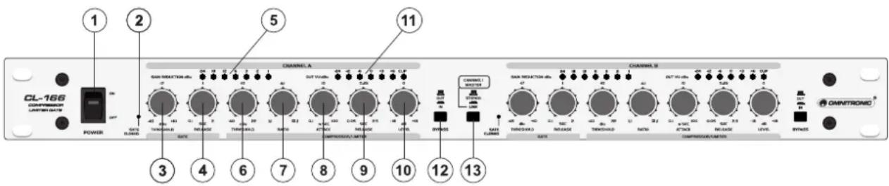
1. POWER Switch
Turns power to the compressor on and off. Be sure to power-up before your power amplifier is turned on to avoid loud transients which could damage your speakers or annoy your audience.
GATE-SECTION
A noise gate is a signal processor that turns off or significantly accentuates the audio signal passing through it when the signal level falls below a user adjustable threshold.
2. GATE LED
This LED lights up when GATE is on processing and thus no signal comes in. As soon as signals are passing through, the LED turns off.
3. THRESHOLD Control
Use the Threshold-Control to determine the threshold point below which expansion occurs. The range of this control is from -45 dB(OFF) to +10 dB. Signals above this threshold value pass unaltered. Adjust this control
English
so that music signals can pass but the noise is faded out. In OFF position, all signals are allowed. By turning it clockwise only signals over the threshold are allowed to limit the noise signal level.
How to set a proper gate level for most applications? Turn off the GATE Threshold. Turn on all instruments hooked to this unit but no input is allowed. Increase the Threshold, the GATE LED comes on. This is helpful in removing hiss from tape, guitar amps etc.
4. RELEASE Control
To optimally adapt the gate to the program material, adjust the Release-control to determine the rate at which the gate closes once the signal falls below the threshold. This control can be adjusted from 0.02 to 2.0 seconds. Use faster release values to process percussive material with little or no ambience. Use slower release values for signals with long decay or heavy ambience.
5. GAIN REDUCTION LED Meter
Displays the attenuation in dB.
COMPRESSOR / LIMITER SECTION
The task of Compressors and Limiters is to reduce the dynamic range of the program material and to control the overall level. It prevents signals from exceeding a given threshold level. The extent of the resulting dynamic level is dependent on Threshold, Attack, Release and Ration settings.
6. THRESHOLD Control
The Threshold control sets the threshold point for the Compressor section. It has a range of -40 to +20 dB.
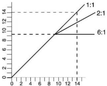
7. RATIO Control
This control determines the ratio between the input and output level for all signals exceeding the threshold point by more than 10 dB. The control range can be adjusted from 1:1 to oo :1. A setting of 1:1 leads to no compression, turning the control clockwise makes the sound increasingly dense. A setting of oo :1 corresponds to a limiter setting.
FIGURE A explains the comparison of compressed signals responding to various Ratio settings.
line
| X | 1:1 | 2:1 | 6:1 | |---|---|---|---| | 0 | 0 | 0 | 0 | | 10 | 9 | 9 | 9 | | 14 | 14 | 13 | 14 |8. ATTACK Control
This control determines the rate by which the compressor responds to the signal which exceeds the threshold. This control can be adjusted from 0.1 ms to 100 ms. Use short Attack times for percussion and slower times soft inaudible compression.
9. RELEASE Control
This control determines the rate that the compressor returns to unity again after falling below the threshold level. This control can be adjusted from 0.1 to 2.5 seconds. Use short times for fast recovery and maximum output and use longer times to avoid pumping.
English
The following diagram shows how the ATTACK/RELEASE works. Different time settings will create different effects. Example: INPUT LEVEL 10 dB at 4 dB compression
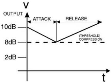
line
| t | OUTPUT | | ---- | ------ | | 0 | 10dB | | 8 | 8dB | | >8 | 2dB |10. LEVEL Control
To adjust the channel or overall output level. Adjust this control to vary the amount of fixed gain in the CL-166's output amplifier stage. This control is especially useful to compensate for RMS level decrease which results from the unit's dynamic processing effects. After you adjust the CL-166's controls for desired amount of compression, set the Level-control to add the same amount of gain that is shown on the Gain Reduction meter. For example, if the average amount of gain reduction shown on the meter is 10 dB, then setting the Level control to 10 dB will compensate for the 10 dB average level reduction at the output.
11. LED LEVEL Meter
Lets you keep an eye on the signal level in order to avoid distortion.
12. BYPASS Selector
This switch allows instant comparison of the original sound with the equalized sound. Note that the Bypass mode works independently for each channel, even if the unit is stereo-coupled (via the Stereo/Link button).
13. STEREO / LINK Button
This button toggles the unit between stereo and dual mono operation. Press the Stereo/Link button IN for stereo operation where CH A becomes the master controller for both channels. All of CH B's controls, buttons and LEDs will be disabled (except for CH B's Bypass button and Gain Reduction LEDs), as CH B is the „slave“. With the Stereo/Link button OUT, the unit works as two separate mono compressor/gates, each with its own independent controls.
Suggested Settings
| ATTACK RELEASE RATIO | |||
| Vocals Medium to Fast | Medium to Slow 2:1 to 4:1 | ||
| Clicky Bass Fast Fast | 4:1 or higher | ||
| Mushy Bass Medium to | Slow Medium to | Slow 4:1 | |
| Raging Electric Guitar | Fast Slow 4:1 or higher | (more sustain) | |
| Acoustic Guitar | Medium to Slow | Medium to Slow 4:1 | |
| Brassy Horns | Fast Fast 5:1 or higher | ||
| Drums (kick, snare) | Fast Fast 4:1 | ||
| Drums (cymbals) | Fast Slow 2:1 to 10:1 | ||
English
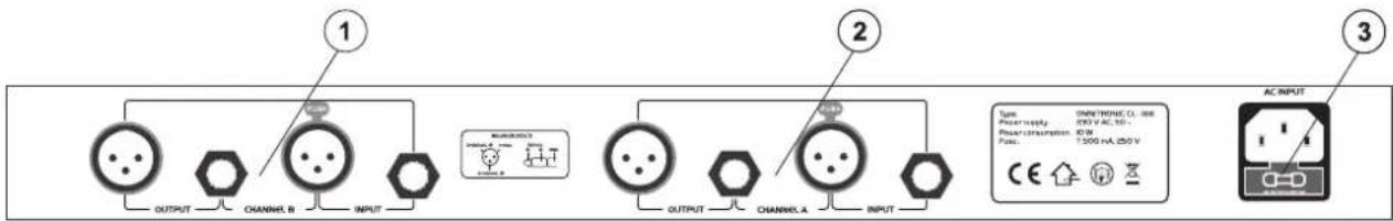
Rear panel
flowchart
graph LR
    A["1"] --> B["OUTPUT"]
    B --> C["CHANNEL_B"]
    C --> D["INPUT"]
    D --> E["CHANNEL_C"]
    E --> F["OUTPUT"]
    F --> G["CHANNEL_A"]
    G --> H["INPUT"]
    H --> I["CHANNEL_B"]
    I --> J["OUTPUT"]
    J --> K["CHANNEL_A"]
    K --> L["INPUT"]
    L --> M["CHANNEL_B"]
    M --> N["OUTPUT"]
    N --> O["CHANNEL_A"]
    O --> P["INPUT"]
    P --> Q["CHANNEL_B"]
    Q --> R["OUTPUT"]
    R --> S["CHANNEL_A"]
    S --> T["INPUT"]
    T --> U["CHANNEL_B"]
    U --> V["OUTPUT"]
    V --> W["CHANNEL_A"]
    W --> X["INPUT"]
    X --> Y["CHANNEL_B"]
    Y --> Z["OUTPUT"]
    Z --> AA["CHANNEL_A"]
    AA --> AB["INPUT"]
    AB --> AC["CHANNEL_B"]
    AC --> AD["OUTPUT"]
    AD --> AE["CHANNEL_A"]
    AE --> AF["INPUT"]
    AF --> AG["CHANNEL_B"]
    AG --> AH["OUTPUT"]
    AH --> AI["CHANNEL_A"]
    AI --> AJ["INPUT"]
    AJ --> AK["CHANNEL_B"]
    AK --> AL["OUTPUT"]
    AL --> AM["CHANNEL_A"]
    AM --> AN["INPUT"]
- Input/Output-Sockets CH-A
- Input/Output-Sockets CH-B
- AC-Connection with Fuseholder
Used to plug the power-cord in.
CLEANING AND MAINTENANCE
DANGER TO LIFE!
Disconnect from mains before starting maintenance operation!
We recommend a frequent cleaning of the device. Please use a soft lint-free and moistened cloth. Never use alcohol or solvents!
There are no servicable parts inside the device except for the fuse. Maintenance and service operations are only to be carried out by authorized dealers.
Replacing the fuse
If the fine-wire fuse of the device fuses, only replace the fuse by a fuse of same type and rating.
Before replacing the fuse, unplug mains lead.
Procedure:
Step 1: Open the fuseholder on the rearpanel with a fitting screwdriver.
Step 2: Remove the old fuse from the fuseholder.
Step 3: Install the new fuse in the fuseholder.
Step 4: Replace the fuseholder in the housing.
Should you need any spare parts, please use genuine parts.
If the power supply cable of this device becomes damaged, it has to be replaced by a special power supply cable available at your dealer.
Should you have further questions, please contact your dealer.
TECHNICAL SPECIFICATIONS
| System specifications: | |
| Power supply: 230 V AC, 50 Hz ~ | |
| Power consumption: 10 W | |
| Fuse: T 0.5 A | |
| Audio inputs/outputs: XLR and 1/4" jack | |
| Input impendance: 10/20 kOhms (unb./bal.) | |
| Output impendance: 300/150 kOhms (unb./bal.) | |
| Frequency response: 20 Hz - | 20 kHz, ±3 dB |
| S/N ratio: 95 dB, unweighted | |
| Crosstalk: >80 dB | |
| THD: 0.05% | |
| Gate section: | |
| Threshold: variable (-45 to +10 dBu) | |
| Release time : variable (0.1 ms to 2 s) | |
| Compressor section: | |
| Threshold: variable (-40 to +22 dBu) | |
| Ratio: variable (1:1 to 00:1) | |
| Attack time: | variable (0.1 ms to 100 ms) |
| Release time: | variable (0.05 sec to 2.5 sec) |
| Output: | variable (-18 to +18 dB) |
| Display: | |
| Gain Reduction: | VU Meter, 7 LEDs |
| Output: | VU Meter, 7 LEDs |
| Dimensions/Weight: | |
| Dimensions (WxDxH): | 483 x 147 x 46 mm |
| Weight: | 2 kg |
Please note: Every information is subject to change without prior notice. 06.09.2006 ©
MODE D'EMPLOI

OMNITRONIC
CL-166
Occupation balanced XLR-connection:
Occupation jack plug:
Raccords d'entrée
- MULTI-LANGUAGE-INSTRUCTIONS
- Français
- LEVEL-Regler
- INTRODUCTION
- Features
- Indispensable Stereo compressor-limiter
- SAFETY INSTRUCTIONS
- CAUTION!
- Important:
- English
- HEALTH HAZARD!
- OPERATING DETERMINATIONS
- DESCRIPTION
- INPUTS
- OUTPUTS
- CONNECTION TO THE MAINS
- INSTALLATION
- RACK MOUNTING
- STARTING UP
- OPERATION
- Front panel
- POWER Switch
- GATE-SECTION
- GATE LED
- THRESHOLD Control
- RELEASE Control
- GAIN REDUCTION LED Meter
- COMPRESSOR / LIMITER SECTION
- THRESHOLD Control
- RATIO Control
- ATTACK Control
- RELEASE Control
- LEVEL Control
- LED LEVEL Meter
- BYPASS Selector
- STEREO / LINK Button
- Rear panel
- CLEANING AND MAINTENANCE
- DANGER TO LIFE!
- Replacing the fuse
- Procedure:
- TECHNICAL SPECIFICATIONS
- MODE D'EMPLOI
- OMNITRONIC
- CL-166
- Occupation balanced XLR-connection:
- Occupation jack plug:
- Raccords d'entrée
Brand : Omnitronic
Model : CL166
Category : Mixer