
Blade mCX2 RTF - Toys E-flite - Free user manual and instructions
Find the device manual for free Blade mCX2 RTF E-flite in PDF.
| Product type | Coaxial radio-controlled helicopter |
| Brand | E-flite |
| Model | Blade mCX2 RTF |
| Category | Toys |
| Length | 200 mm |
| Height | 120 mm |
| Main rotor diameter | 190 mm |
| Weight with battery | 28 g |
| Motors | 2 micro coreless |
| Flight battery | LiPo 1 cell 3.7 V 120 mAh (included) |
| Charger | DC LiPo charger 1 cell 3.7 V 0.3 A (included) |
| Transmitter | MLP4DSM 2.4 GHz DSM 4-channel (included) |
| Transmitter power supply | 4 AA batteries (included) |
| Control unit | 5-in-1: receiver, servos, mixer, ESC, gyro |
| Radio technology | DSM2 2.4 GHz |
| Recommended flying area | Indoor, space of at least 3x3 m and 2.45 m height |
| Main functions | Hovering, forward, backward, sideways, on-the-spot rotation |
| Maintenance | Check blade condition, clean with a dry cloth, charge the LiPo battery safely |
| Safety | Do not use outdoors in wind, keep away from people, cut throttle in case of crash |
| Spare parts | Available: blades, motors, shafts, batteries, etc. (references in the manual) |
| Repairability | User repairable, spare parts available |
| Warranty | 6 months, 18 months warranty obligation |
Frequently Asked Questions - Blade mCX2 RTF E-flite
User questions about Blade mCX2 RTF E-flite
0 question about this device. Answer the ones you know or ask your own.
Ask a new question about this device
Download the instructions for your Toys in PDF format for free! Find your manual Blade mCX2 RTF - E-flite and take your electronic device back in hand. On this page are published all the documents necessary for the use of your device. Blade mCX2 RTF by E-flite.
USER MANUAL Blade mCX2 RTF E-flite
Note: Attempting to fly the helicopter without completely reading the manual may cause Injury to yourself and people in the vicinity, as well as damage to the helicopter.
| Troubleshooting | 2 |
| Specifications | 2 |
| Warning | 3 |
| Additional Safety Precautions and Warnings | 3 |
| Blade® mCX2 RTF Contents | 3 |
| Blade mCX2 BNF Contents | 4 |
| First Flight Preparation | 4 |
| Flying Checklist | 4 |
| Battery Warnings and Guidelines | 4 |
| Battery Charging | 6 |
| Installing the Transmitter Batteries (RTF ONLY) | 6 |
| Installing the Flight Battery | 7 |
| Transmitter and Receiver Binding | 7 |
| Transmitter Control Identification | 9 |
| Control Test | 10 |
| Channel 5 Information | 12 |
| 5-in-1 Control Unit Description, Arming and Motor Control Test | 12 |
| Understanding the Primary Flight Controls | 14 |
| Dual Rates | 16 |
| Choosing a Flying Area | 17 |
| Flying the Blade mCX2 | 17 |
| Advanced Swashplate Settings | 18 |
| Troubleshooting Guide | 19 |
| Exploded View Parts Listing | 20 |
| Exploded View | 21 |
| Replacement Parts List | 22 |
| Option Parts | 22 |
| Warranty and Repair Policy | 24 |
| Compliance Information for the European Union | 26 |
Troubleshooting
If you encounter any difficulties while charging, setting up, testing functions or flying your Blade mCX2, see page 24 to contact the appropriate Horizon Product Support office.
Specifications
| Length | 7.9 in (200mm) |
| Height | 4.7 in (120mm) |
| Main Rotor Diameter | 7.5 in (190mm) |
| Weight with Battery | 1.0 oz (28 g) |
| Main Motors | Micro coreless (2 installed) |
| Battery | 1-Cell 3.7V 120mAh LiPo (included) |
| Charger | 1-Cell 3.7V DC LiPo (included) |
| Transmitter | MLP4DSM 2.4GHz DSM 4-channel (RTF Only) |
| On-Board Electronics | 5-in-1 receiver/servos/mixer/ESCs/gyro (installed) |
Warning
An RC helicopter is not a toy! If misused, it can cause serious bodily harm and damage to property. Fly only in open areas, preferably at AMA (Academy of Model Aeronautics) approved flying sites, following all instructions.
Keep items that can get entangled in the rotor blades away from the main and tail blades, including loose clothing, pencils and screwdrivers. Especially keep your hands away from the rotor blades.
Additional Safety Precautions andWarnings
As the user of this product, you are solely responsible for operating it in a manner that does not endanger yourself and others or result in damage to the product or the property of others.
This model is controlled by a radio signal that is subject to interference from many sources outside your control. This interference can cause momentary loss of control so it is advisable to always keep a safe distance in all directions around your model, as this margin will help to avoid collisions or Injury.
Never operate your model with low transmitter batteries.
Always operate your model in an open area away from cars, traffic or people.
Avoid operating your model in the street where injury or damage can occur.
Never operate the model out into the street or populated areas for any reason.
- Carefully follow the directions and warnings for this and any optional support equipment (chargers, rechargeable battery packs, etc.).
Keep all chemicals, small parts and anything electrical out of the reach of children.
- Moisture causes damage to electronics. Avoid water exposure to all equipment not specifically designed and protected for this purpose.
- Never lick or place any portion of your model in your mouth as it could cause serious injury or even death.
Blade® mCX2 RTF Contents
| Item | Description |
| Not Available Separately | Blade mCX2 RTF Airframe |
| EFLH1064B | MLP4DSM 4-Channel Transmitter, 2.4GHz DSM2 |
| EFLB1201S | 120mAh 1-Cell 3.7V Li-Po |
| EFLC1000 | 1-Cell 3.7V Li-Po Charger, 0.3A |
| EFLH1209 | Screwdriver |
| Not Available Separately | 8 AA Batteries |
| (Optional) FUG4 | 4 AA Batteries |

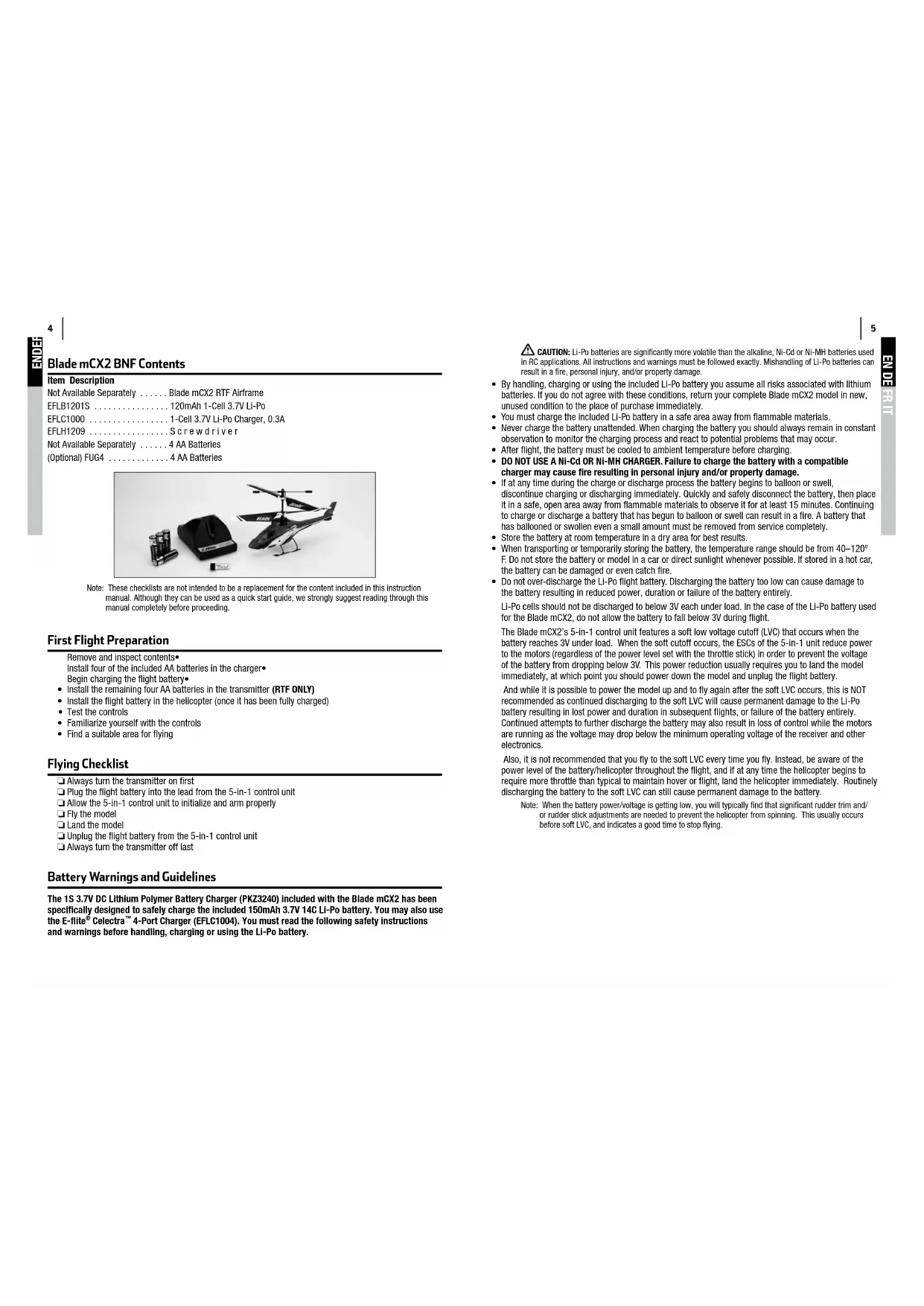
Blade mCX2 BNF Contents
Item Description
Not Available Separately . . . . . . . . . . . . . . . . . . . . . . . . . . . . . . . . . . . . . . . . . . . . . . . . . . . . . . . . . . . . . . . . . . . . . . . . . . . . . . . Blade mCX2 RTF Airframe
EFLB1201S 120mAh 1-Cell 3.7V Li-Po
EFLC1000 1-Cell 3.7V Li-Po Charger, 0.3A
EFLH1209 .Screwdriver
Not Available Separately 4 AA Batteries
(Optional) FUG4 4 AA Batteries

Note: These checklists are not intended to be a replacement for the content included in this instruction manual. Although they can be used as a quick start guide, we strongly suggest reading through this manual completely before proceeding.
First Flight Preparation
Remove and Inspect contents
Install four of the included AA batteries in the charger
Begin charging the flight battery
Install the remaining four AA batteries in the transmitter (RTF ONLY)
Install the flight battery in the helicopter (once it has been fully charged)
Test the controls
Familiarize yourself with the controls
Find a suitable area for flying
Flying Checklist
Always turn the transmitter on first
Plug the flight battery into the lead from the 5-in-1 control unit
Allow the 5-in-1 control unit to initialize and arm properly
Fly the model
Land the model
Unplug the flight battery from the 5-in-1 control unit
Always turn the transmitter off last
BatteryWarnings and Guidelines
The 1S 3.7V DC Lithium Polymer Battery Charger (PKZ3240) included with the Blade mCX2 has been specifically designed to safely charge the Included 150mAh 3.7V 14C Li-Po battery. You may also use the E-flight Celestra™ 4-Port Charger (EFLC1004). You must read the following safety instructions and warnings before handling, charging or using the Li-Po battery.
CAUTION: Li-Po batteries are significantly more volatile than the alkaline, Ni-Cd or Ni-MH batteries used in RC applications. All instructions and warnings must be followed exactly. Mishandling of Li-Po batteries can result in a fire, personal injury, and/or property damage.
- By handling, charging or using the included Li-Po battery you assume all risks associated with lithium batteries. If you do not agree with these conditions, return your complete Blade mCX2 model in new, unused condition to the place of purchase immediately.
- You must charge the included Li-Po battery in a safe area away from flammable materials.
- Never charge the battery unattended. When charging the battery you should always remain in constant observation to monitor the charging process and react to potential problems that may occur.
After flight, the battery must be cooled to ambient temperature before charging. - DO NOT USE A NI-Cd OR NI-MH CHARGER. Failure to charge the battery with a compatible charger may cause fire resulting in personal injury and/or property damage.
- If at any time during the charge or discharge process the battery begins to balloon or swell
discontinue charging or discharging immediately. Quickly and safely disconnect the battery, then place it in a safe, open area away from flammable materials to observe it for at least 15 minutes. Continuing to charge or discharge a battery that has begun to balloon or swell can result in a fire. A battery that has ballooned or swollen even a small amount must be removed from service completely. - Store the battery at room temperature in a dry area for best results.
- When transporting or temporarily storing the battery, the temperature range should be from 40 - 120^ F. Do not store the battery or model in a car or direct sunlight whenever possible. If stored in a hot car, the battery can be damaged or even catch fire.
- Do not over-discharge the Li-Po flight battery. Discharging the battery too low can cause damage to the battery resulting in reduced power, duration or failure of the battery entirely.
Li-Po cells should not be discharged to below 3V each under load. In the case of the Li-Po battery used for the Blade mCX2, do not allow the battery to fall below 3V during flight.
The Blade mCX2's 5-in-1 control unit features a soft low voltage cutoff (LVC) that occurs when the battery reaches 3V under load. When the soft cutoff occurs, the ESCs of the 5-in-1 unit reduce power to the motors (regardless of the power level set with the throttle stick) in order to prevent the voltage of the battery from dropping below 3V. This power reduction usually requires you to land the model immediately, at which point you should power down the model and unplug the flight battery.
And while it is possible to power the model up and to fly again after the soft LVC occurs, this is NOT recommended as continued discharging to the soft LVC will cause permanent damage to the Li-Po battery resulting in lost power and duration in subsequent flights, or failure of the battery entirely. Continued attempts to further discharge the battery may also result in loss of control while the motors are running as the voltage may drop below the minimum operating voltage of the receiver and other electronics.
Also, it is not recommended that you fly to the soft LVC every time you fly. Instead, be aware of the power level of the battery/helicopter throughout the flight, and if at any time the helicopter begins to require more throttle than typical to maintain hover or flight, land the helicopter immediately. Routinely discharging the battery to the soft LVC can still cause permanent damage to the battery.
Note: When the battery power/voltage is getting low, you will typically find that significant rudder trim and/or rudder stick adjustments are needed to prevent the helicopter from spinning. This usually occurs before soft LVC, and indicates a good time to stop flying.
Battery Charging
Follow these steps to charge the Li-Po battery with the included charger:
- Remove the cover on the bottom of the charger and install four of the included AA batteries, noting proper polarity. Replace the cover after the AA batteries are installed.
- Slide the battery into the slot on the charger. The endcap of the battery has been specifically designed to allow the battery to be slid into the slot easily one way (usually with the label on the battery facing outward) to prevent reverse polarity connection. However, check for proper alignment and polarity before proceeding to the next step.
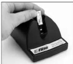
- Gently press the battery and its connector into the charge jack/connector located at the bottom of the slot on the charger.
- Once the connection is successful, the LED light on the charger turns solid red, indicating charging has begun.
A fully discharged battery (not over-discharged) takes
approximately 30-40 minutes to charge. As the battery nears full charge, the LED light will blink. When the battery is fully charged the LED light blinks approximately every 20 seconds or goes out entirely.
Note: The Li-Po battery included with your Blade mCX2 will arrive partially charged. For this reason the initial charge may only take 15-20 minutes.
Note: You can expect to charge the Li-Po flight battery approximately 15-20 times before it will be necessary to replace the AA batteries in the charger.
An optional 6V power supply is also available separately (EFLC1005). This power supply will allow you to charge at home without the need for AA batteries.
Installing the Transmitter Batteries (RTF ONLY)
Install four of the included AA batteries in the transmitter. Check for proper operation of the transmitter by switching the power switch on (to the left). The LED light at the top of the transmitter should begin to glow solid red while the transmitter beeps.

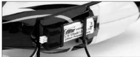
Installing the Flight Battery
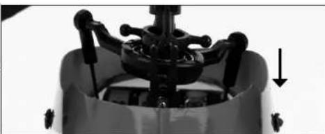
Once the Li-Po battery is fully charged, you can install it in the helicopter. This is done by sliding it into the battery mounting supports/slots just below the main gears. Slide the battery into the slots with the label facing downward and the connector oriented toward the back of the helicopter.
Note: Be sure to slide the battery into the slots until the endcap of the battery comes into contact with the rear battery support. This allows you to achieve the correct center of gravity for the best overall flight performance. However, be sure the battery is not pushed far enough forward that it makes contact with the servo gears, as this could cause damage to the gears and a potential crash.
Transmitter and Receiver Binding
The Blade mCX2 RTF comes bound to the MLP4DSM transmitter included.
The BNF version requires you to bind to your own compatible DSM2 Aircraft Transmitter.
To bind or re-bind your mCX2 to your chosen transmitter please follow the directions below:
Binding is the process of programming the receiver of the control unit to recognize the GUID (Globally Unique Identifier) code of a single specific transmitter. You need to 'bind' your chosen Spektrum DSM2 technology equipped aircraft transmitter to the receiver for proper operation.
Following are some of the Spektrum DSM2-equipped transmitters and modules that bind to the receiver of your Blade mCX2.
E-1ite MLP4DSM
E-Ilite LP5DSM
ParkZone Vapor Transmitter
PKZ Ember 2 Transmitter
JR 12X 2.4
JR X9303 2.4
Spektrum DX5e
Spektrum DX6i
Spektrum DX7/DX7se
Note: The Spektrum DX6 (SPM2460) is equipped with DSM (not DSM2) technology and is not compatible with the receiver of the Blade mCX2.
The following steps outline the binding process:
- Make sure the flight battery is disconnected from the 5-in-1 unit and the transmitter is turned off.
- Plug the flight battery into the 5-in-1 unit.
- Plug the flight battery into the 5-in-1 unit. After 5 seconds the LED on the 5-in1 unit will begin flashing.
MLP4DSM and ParkZone Vapor/Ember 2 Transmitters
After verifying the LED is flashing on the receiver/5-in-1, PUSH directly down on the left-hand stick while switching the transmitter on (you will feel a 'click' when you push in on the end of the stick).
After approximately 5-10 seconds the receiver/5-in-1 should be bound to the transmitter and you should now have full control and function.
LP5DSM
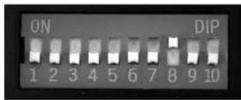
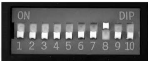
If you decide to use an E-flight LP5DSM transmitter, please position your channel reversal dip switches as follows.

- Plug the flight battery into the 5-in-1 unit. After 5 seconds the LED on the 5-in-1 unit will begin flashing.
- Move the sticks and switches on the transmitter to the desired failsafe positions (low throttle and neutral control positions).
- Turn the transmitter on. The red LED located under the door on the bottom left front of the transmitter will blink rapidly.
DX5e and DX6i
- Move the sticks and switches on the transmitter to the desired failsafe positions (low throttle and neutral control positions).
- For the DX5e: Pull and hold the Trainer Switch on the transmitter while turning the transmitter on. Release the trainer switch once the LEDs on the front of the transmitter flash.
- For the DX6i: Pull and hold the Trainer Switch on the transmitter while turning the transmitter on. Release the trainer switch once "BIND" Flashes on the LCD screen of the transmitter.
- After approximately 5-10 seconds the receiver/5-in-1 should be bound to the transmitter and you should have full control and function.
DX7, DX7se, X9303, or 12X:
- Move the sticks and switches on the transmitter to the desired failsafe positions (low throttle and neutral control positions)
- Press the bind button on the back of the transmitter while turning the transmitter on. The bind button on the back of the transmitter will flash. Release the button after 2-3 seconds.
- After approximately 5-10 seconds the receiver/5-in-1 should be bound to the transmitter and you should now have full control and function.
Additional Binding Information
Prior to each flight, power on your transmitter and wait about five seconds before you plug the flight battery into the receiver. This allows time for the transmitter to scan and secure two open frequencies. If you plug the flight battery in too quickly and miss the link, the receiver may inadvertently enter bind mode. If this occurs leave the transmitter on, then disconnect and reconnect the flight battery.
Transmitter Control Identification

Control Test
Although each Blade mCX2 model is test flow at the factory, you should test the controls prior to the first flight to ensure none of the servos, linkages or parts were damaged during shipping and handling.
Turn the transmitter on first and lower the throttle stick completely. Then, plug the battery into the battery lead of the 5-in-1 unit.
Note: The connectors on the battery and battery lead are keyed to prevent reverse polarity connection. However, if you force them together in the wrong orientation/ wrong polarity it is possible to damage the battery and/or 5-in-1 unit. To help further prevent a reverse polarity connection, one side of the endcap on the battery and the connector on the battery lead of the 5-in-1 unit have a red dot. The connectors are oriented for a proper polarity connection when the red dots are on the same side (usually toward the top of the helicopter).


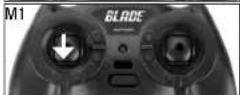
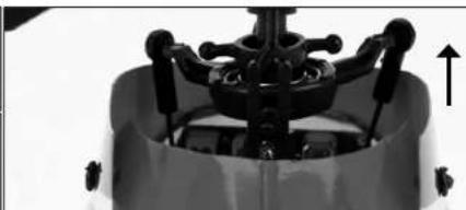
Position the helicopter to view it from behind. Move the elevator stick on the transmitter forward and aft to check elevator pitch control. When the stick is pushed forward, the right-hand servo should pull the swashplate downward.

With the stick pulled back, the right-hand servo should push the swashplate upward.

Move the right-hand stick left and right to check alleron roll control. When the stick is pushed to the left, the left-hand servo should pull the swashplate downward.
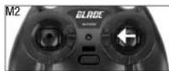

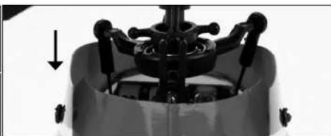
With the stick pushed right, the left-hand servo should push the swashplate upward.


If at any time during the test the controls respond in the opposite direction, it may be necessary to reverse/change the direction of operation of the flight controls. Follow these steps to change the direction the various flight controls:
- Be certain that the battery is disconnected from the battery lead of the 5-in-1 control unit and the transmitter is turned off.
- Push down on the appropriate digital trim button on the transmitter for the control you would like to change the direction of. For example:
Top elevator trim button—elevator channel normal
Bottom elevator trim button—elevator channel reversed
Left aileron trim button—aileron channel normal
Right aileron trim button—alleron channel reversed
Continue to hold the appropriate trim button while turning the transmitter on.
- Hold the digital trim button down for approximately five seconds, until a series of beeps/tones are heard confirming the selection.
- Connect the battery to the 5-in-1 and complete the flight control test, confirming that all controls are operating in the correct directions.
12
If you decide to use an E-flight LP5DSM transmitter, please position your channel reversal dip switches as follows:
If you've confirmed proper control operation of your Blade mCX2, unplug the flight battery.
Channel 5 Information
Channel 5 affects rate settings of the 5-in-1 Control Unit.
If using the stock MLP4DSM Transmitter, please read Page 21 of this manual for Dual Rate information. If using an LP5DSM Transmitter, please turn the Channel 5 knob clockwise completely.
- If using any other DSM2 compatible transmitter, please ensure Channel 5 is set to default servo reversal and the switch or knob is set to a position that allows full travel control.
Note: This can easily be tested by inducing full cyclic (Aileron/Elevator) input and moving the switch or knob.
There's approximately 10-15% less servo travel depending on what position Channel 5 is in.
5-in-1 Control Unit Description, Arming and Motor Control Test
The unique Control Unit installed on your Blade mCX2 is a lightweight combination of main motor electronic speed controls, mixer, gyro, servos and Spektrum DSM2 compatible receiver. The 5-in-1 unit is also equipped with a status indicator LED.

The following checklist contains the steps to ensure proper arming and operation of the control unit, as well as proper motor response:
Before each flight ALWAYS turn the transmitter on before connecting the flight battery to the 5-in-1 unit. Never connect the flight battery to the 5-in-1 unit before powering the transmitter on first. After each flight, always disconnect the flight battery from the 5-in-1 unit before powering the transmitter off.
Note: The only time you should connect the flight battery to the 5-in-1 unit before powering the transmitter on is when you are binding the receiver of the 5-in-1 unit to the transmitter. Please see the Transmitter and Receiver Binding section of this manual for more information.
The throttle stick MUST be set in the lowest possible position, and the throttle trim must be set to the middle or a lower than middle position (the middleposition is indicated by a longer than usual beep/ tone), in order for the 5-in-1 unit to arm.
If this is the first test flight, or a test flight following repairs, you should also center the rudder, aileron and elevator trims.
Set throttle stick to lowest position.
Set throttle stick to lowest position.


After confirming that the transmitter has been turned on and that the LED is glowing solid BLUE, it is now safe to connect the flight battery to the 5-in-1 unit.
With the transmitter turned on and the LED glowing solid BLUE, it is now safe to connect the flight battery to the 5-in-1 unit.
- With battery power applied to the 5-in-1 unit, the status indicator LED should glow solid BLUE within a few seconds.
Note: It is extremely important that you do not move, sway or pretend to fly the helicopter once the flight battery is connected because the initialization process and calibration of the gyro has begun. If you do move the helicopter before the LED is solid BLUE, disconnect the flight battery from the 5-in-1 unit and repeat the initialization process.
- When the status LED becomes solid BLUE, the control unit is initialized and ready for flight. Also, as long as you set the throttle stick and trim to the correct positions during the initialization process, the ESCs/motors will now be armed. Use caution as both rotor blades will now spin with throttle stick input.
Note: If the status LED does not become solid BLUE, please review the following:
- If after BLUE status LED becomes solid, but you have no control of the motors, you have a positive Radio Frequency (RF) link between the transmitter and receiver, but the throttle stick and throttle trim may not be set to the correct positions. Check that the throttle stick is in the lowest possible position, and the throttle trim is set to the middle or a lower than the middle position. If you now have control of the motors, proceed to the next step of the checklist.
- If BLUE status LED is off completely, you do not have a positive RF link between the transmitter and receiver. Check that the transmitter has been powered on and the LED indicator on the transmitter is glowing solid red. If the transmitter is powered on and functioning properly, disconnect the flight battery from the 5-in-1 unit, then reconnect it. The 5-in-1 unit should initialize and arm properly.
Once you place the helicopter in a safe area, free of obstructions, and are clear of the rotor blades, you can safely power up the model to check for proper operation of the motors.
Advance the throttle stick upward slowly, just until both rotor blades begin to spin. DO NOT attempt to fly the helicopter at this time. Note the direction each of the rotor blades spins. When viewed from the top, the upper main rotor blades should spin counterclockwise and the lower main rotor blades should spin clockwise. If either set of rotor blades is operating in the wrong direction, disconnect the battery and reverse the polarity of the corresponding motor's input power leads.
After confirming the rotor blades rotate in the correct direction, confirm that both rotor blades respond properly to rudder control inputs.
14
With the rotor blades spinning at a low level of power, move the rudder (left-hand) stick all the way to the right. This should cause the speed of the upper main rotor blade to increase, and the speed of the lower main rotor blade to decrease.
Next, move the rudder stick all the way to the left. This should cause the speed of the lower main rotor blade to increase and the speed of the upper main rotor blade to decrease. If both rotor blades are not responding properly to rudder input, simply reverse the locations of their motor plugs on the 5-in-1 unit.
With both rotor blades rotating in the correct directions and responding properly to rudder inputs, your Blade mCX2 is ready for flight. But you will need to review the following sections of the manual BEFORE proceeding with the first flight.
Understanding the Primary Flight Controls
If you are not familiar with the controls of your Blade mCX2, please take a few minutes to familiarize yourself with them before attempting your first flight.
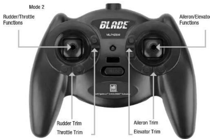
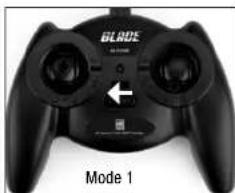
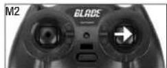
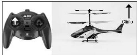
For Mode 2 transmitters: The left-hand stick on the transmitter controls both throttle (climb/descend) and rudder (yaw left/right). When the throttle stick is in the lowest possible position and throttle trim is set to the middle or a lower than the middle position, the main rotor blades will not spin. Advancing the stick upward increases the speed of the main rotor blades, causing the model to climb.
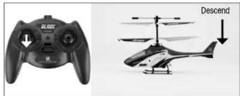
Decreasing the speed of the main rotor blades by lowering the throttle stick causes the model to descend.
Once the model is off the ground to balance the throttle, carefully move the left-hand stick up and down so the model holds a stationary hover (without climbing or descending).
Moving the rudder stick to the left turns the nose of the helicopter left about the axis of the main shaft. This is accomplished by increasing the speed of the lower main rotor blade while decreasing the speed of the upper main rotor blade.

Moving the stick to the right turns the nose of the helicopter right about the axis of the main shaft. This is accomplished by increasing the speed of the upper main rotor blade while decreasing the speed of the lower main rotor blade.

Use rudder trim to help keep the nose of the helicopter from rotating left or right when in hover with no rudder stick input. For example, if the nose of the helicopter drifts to the right when in hover, add left rudder trim (by pressing the left rudder trim button) until the nose stays as close to straight as possible.
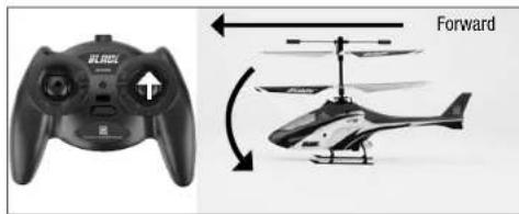
The elevator stick controls both elevator (pitch fore/af). Push the stick forward to pitch the nose of the helicopter down and fly forward.
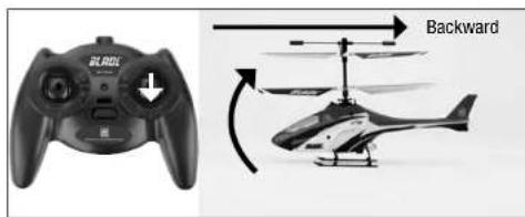
Pull the stick back to pitch the tail down and fly backward.
Use elevator trim to keep the helicopter from drifting forward or backward when hovering with no elevator stick input. For example, if the helicopter drifts forward, add back/up elevator trim until it hovers as level as possible with no drifting.
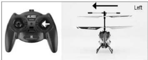
Move the aileron stick left to fly the helicopter left.
Move the stick right to fly the helicopter to the right.

Use aileron trim to keep the helicopter from drifting left or right when hovering with no aileron stick input. For example, if the helicopter drifts to the right when hovering, add left aileron trim until it hovers as level as possible with no drifting to the right.
Once familiar with the primary controls of the helicopter, you are almost ready to fly.
Dual Rates
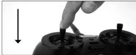
The MLP4DSM transmitter included with your Blade mCX2 RTF is equipped with a dual rate feature. This feature allows the pilot to toggle between the high and low control rates available for the aileron, elevator and rudder channels. To toggle between the high and low rates, push in on the right-hand stick on the transmitter (while the transmitter is powered on).
The transmitter comes set in high-rate mode. You can tell you are in the high-rate mode when the LED on the transmitter glows solid red. In high-rate mode the controls are allowed to reach their maximum values, typically preferred by experienced pilots for maximum control authority.
Push the right-hand stick in while in high-rate mode to enter low-rate mode. You can tell you are in the low-rate mode when the LED on the transmitter blinks continuously. The low-rate mode is typically preferred by (and best for) first-time, low-time and other pilots most interested in reduced control that allows for smoother and more easily controlled hovering and flying.
Note: The throttle curve in the low rate mode is also different than it is in the high rate mode. This makes low-rate-mode throttle smoother and easier to control.
Choosing a Flying Area
When ready for your first flight, select a relatively open indoor area free of people and obstructions. While it is possible for experienced pilots to fly the Blade mCX2 in relatively small indoor areas with great success, we strongly recommend an area with at least 10-feet by 10-feet of floor space and no less than 8-foot ceilings when making your first few flights.
Once you properly trim your helicopter and become familiar with its handling and capabilities, you will be able to fly in other smaller, less open areas.
Note: The Blade mCX2 is designed and intended to be flown INDOORS ONLY.
Flying the Blade mCX2
Note: In addition to reviewing the flight maneuvers outlined below, we recommend you watch Videos located on the product page for the Blade mCX2 on www.horizonhobby.com to see many of these maneuvers and adjustments performed by the helicopter and pilot.
- Slowly raise the throttle stick, increasing the speed of the main rotor blades until the model begins to lift off. Do not raise the throttle stick too quickly as the model could climb too fast causing you to lose control or make contact with objects above.
- Lift the model off the ground just a few inches and concentrate on balancing the throttle stick position so that the model holds a steady hover altitude. In some cases it may be best to make a few short "hops" to an altitude of just a few inches until you become familiar with the control inputs and trim settings required to maintain a steady hover and altitude.
As you will find, the Blade mCX2 requires minor throttle adjustments to maintain its altitude in hover. Remember to keep these throttle adjustments as minimal as possible as large adjustments could result in a loss of control and/or a possible crash.
-
While attempting to establish a low-level hover, you can also check to see if any trim adjustments are required to help keep the Blade mCX2 from constantly drifting in various directions. If you find the helicopter constantly drifts without any directional control input, it will be best to land the model before making any adjustments to the trim settings. Additional details regarding the location and function of the trim buttons can be found in the "Understanding the Primary Flight Controls" section of this manual.
-
If the nose of the helicopter drifts to the left or right, adjust the rudder trim.
-
If the helicopter drifts forward or backward, adjust the elevator trim.
- If the helicopter drifts to the left or right, adjust the aileron trim.
Continue making trim adjustments until the helicopter hovers at a low attitude with very little drifting and directional control input. If the Blade mCX2 is your first helicopter model, it may be best to have the help of an experienced helicopter pilot to trim the model for you before making your first flight.
- With your Blade mCX2 properly trimmed and maintaining a stable low-level hover, practice using the rudder, elevator and alleron controls to familiarize yourself with the helicopter's responses to control inputs. Remember to keep the control inputs as minimal as possible.
When comfortable with low-level hovering, you can transition to hovering and flying the helicopter at higher altitudes of three to four feet. At these higher altitudes you will become comfortable with the flight characteristics of the Blade mCX2.
If you feel the helicopter drifting out of control during flight, release all of the controls except for throttle. You will need throttle to maintain altitude, but because of the inherent stability of the coaxial, counter-rotating blade design, the Blade mCX2 will return to a stable hover on its own, if space allows.
- Don't be afraid to set the helicopter down on the ground quickly by lowering the throttle when approaching walls or other obstacles to help prevent main rotor blade strikes. IN THE EVENT OF A CRASH OR ROTOR BLADE STRIKE, NO MATTER HOW MINOR OR MAJOR, LOWER THE THrottLE STICK TO THE LOWEST POSSIBLE POSITION AS QUICKLY AS POSSIBLE TO PREVENT DAMAGE TO THE ESCS OF THE 5-IN-1 UNIT. ALSO BE SURE THE THROTTLE TRIM IS SET TO THE MIDDLE POSITION OR TO A LOWER THAN THE MIDDLE POSITION.
Failure to lower the throttle stick to the lowest possible position in the event of a crash could result in damage to the ESCs in the 5-in-1 unit, which may require replacement of the 5-in-1 unit. Note: Crash damage is not covered under warranty.
Once you have gained experience and confidence in hovering the Blade mCX2, you can attempt more advanced maneuvers including:
Forward Flight Backward Flight Skidding Takeoffs
Pirouettes Spot Landings Skidding Landings
Advanced Swashplate Settings
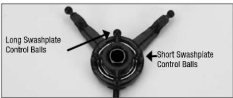
The Blade mCX2 comes with an adjustable swashplate. Advanced pilots may benefit from a more aggressive setup. To achieve a more aggressive setup, pop off the lower rotor head links and move them onto the longer set of Inner swashplate control balls.
Troubleshooting Guide
| Problem Solution | |
| Aircraft will not "throttle up" but all other controls seem to function. | • Lower throttle stick and throttle trim to their lowest settings. • Reverse throttle channel on specific transmitter if applicable. |
| Upper rotor head/hub is broken. • Replace with EFLH2412 by carefully removing the (2) screws in the lower main gear and transferring all unbroken parts to the new upper rotor head/hub. Follow the "Exploded View" section of the manual. Pages 20-21 | |
| Aircraft appears to show significant decrease in flight time. | • Recharge flight battery completely. • Replace AA batteries in the charger and recharge flight battery completely. • Replace EFLB1201S battery and read "BatteryWarnings and Guidelines" section of manual. Pages 4-5 |
| Charger light stays on after Li-Po battery is disconnected or remains on for longer than 40 minutes when charging. | • Replace AA batteries in the charger. |
| Aircraft hovers with a "toilet bowl" effect type circle on its own. | • Loosen upper rotor hub fly bar retaining screw. • Replace rotor blades. |
| LED on Aircraft remains flashing and cannot be controlled by transmitter. | • Unplug, then reconnect flight battery. • Retrain Aircraft to your desired compatible transmitter. Pages 7-8 • Move transmitter (powered on) a few feet from the Aircraft prior to reconnecting the flight battery. |
| Aircraft appears to drift towards a certain direction. | • Read "Understanding the Primary Flight Controls" section of this manual. Pages 14-16 |
| Controls appear to be reversed after binding to a different transmitter. | • Read "Control Test" section of this manual. Pages 10-12 |
| Aircraft constantly spins on its own. | • Center the rudder trim on your transmitter and re-initialize the aircraft. • Unplug, then reconnect the flight battery and DO NOT move or sway the helicopter during initialization. • Read "Understanding Primary Controls" section of this manual. Pages 14-16 • Loosen (2) screws on the lower main gear and ensure there is slight "play" in between the upper and lower main gears. Lube between the upper and lower main gears if applicable. |
| Aircraft does not function after connecting flight battery and aircraft smells burnt. | • Replace 5-in-1 board (EFLH2401) and ensure the RED polarity marks are facing the same direction when connect-ing the flight battery to the 5-in-1 board. |
Exploded View Parts Listing
Item Number Description
1 EFLH2219B .Stabilizer Flybar Set
2 EFLH2412 .Inner Shaft with Head/Hub
3 EFLH2421 .Upper Main Blade Set (1 pr)
4 EFLH2421. Upper Main Blade Set (1 pr)
5 EFLH2225 ST1.2 x 5 (2) Screw
6 EFLH2412 .Inner Shaft with Head/Hub
7 EFLH2213 Outer Shaft, Main Gear and Bushing Holder Set
8 EFLH2420 .Lower Main Blade Set (1 pair)
9 EFLH2213 .Outer Shaft, Main Gear and Bushing Holder Set
10 EFLH2217 .........Lower Rotor Head and Linkage Set
11 EFLH2225 M1.2 x 1.8 (2) Screw
12 EFLH2410 .Motor with Pinion, Counterclockwise
13 EFLH2416 .Swashplate (1)
14 EFLH2416 .Swashplate (1)
15 EFLH2416 .Swashplate (1)
16 EFLH2214 Outer Shaft Retaining Collar Set
17 EFLH2409 .Motor with Pinion, Clockwise
18 EFLH2418 .Servo Pushrod Set
19 EFLH2418 .Servo Pushrod Set
20 EFLH2424 Main Frame Set
21 EFLH1066 .Replacement Servo Mechanics
22 EFLH2401 5-In-1 Control Unit, RX/Servos/ESCs/Mxr/Gyro
23 EFLH2225 . . . . . . . . . . . . . . . . . . . . . . . . . . . . . . . . . . . . . . . . . . . . . . . Washers
24 EFLH2225 .ST1.2 x 5 (2) Screw
25 EFLH2427 Complete Red Canopy with LEDs (installed)
26 EFLH2211 .Inner Shaft Main Gear
27 EFLH2211 .Inner Shaft Main Gear
28 EFLH2222 .Landing Skid and Battery Mount Set
29 EFLH2225 M1.2 x 2.5 (2) Screw
30 EFLB1201S 120mAh 1-Cell 3.7V 14C Li-Po
31 EFLH2213 Outer Shaft, Main Gear and Bushing Holder Set
32 EFLH2215 .Outer Shaft Bearing 3× 6× 2mm (2)
33 EFLH3021 .Canopy Mounting Grommets (8)
34 EFLH2427 Complete Red Canopy with LEDs (installed)
35 EFLH2404 .Replacement LED Set (4)
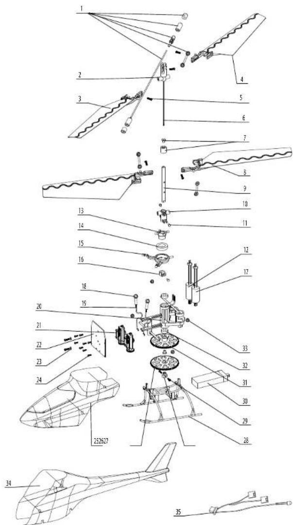
Exploded View
EFLB1201S 120mAh 1-Cell 3.7V 14C LI-Po
EFLC1000 1-Cell 3.7V 0.3A DC Li-Po Charger
EFLH1064B. Blade MLP4DSM 4-channel Transmitter, 2.4GHz
EFLH1066 Replacement Servo Mechanics
EFLH1067 Replacement Servo Retaining Collars
EFLH2211 .Inner Shaft Main Gear
EFLH2213. Outer Shaft, Main Gear and Bushing Holder Set
EFLH2214 Outer Shaft Retaining Collar Set
EFLH2215 Outer Shaft Bearing 3× 6× 2mm (2)
EFLH2217 .Lower Rotor Head and Linkage Set
EFLH2219B. Stabilizer Flybar Set
EFLH2222 Landing Skid and Battery Mount Set
EFLH2225 . Hardware Set
EFLH2401. 5-In-1 Control Unit, Receiver/Servos/ESCs/Mixer/Gyro
EFLH2404 . Replacement LED Set (4)
EFLH2409 .Motor with Pinion, Clockwise
EFLH2410 Motor with Pinion, Counter-Clockwise
EFLH2412. Inner Shaft with Head/Hub
EFLH2416 .Swashplate (1)
EFLH2418 .Servo Pushrod Set
EFLH2420 .Lower Main Blade Set (1 pr)
EFLH2421 Upper Main Blade Set (1 pr)
EFLH2424 Main Frame Set
EFLH2427 Complete Red Canopy with LEDs (Installed)
EFLH3021 .Canopy Mounting Grommets (8)
EFLB1501S 150mAh 1-Cell 3.7V Li-Po
EFLC1005 .6V AC Power Supply
EFLH2220GL. Lower Main Blade Set, Glow-in-the-Dark (1 pr)
EFLH2221GL. Upper Main Blade Set, Glow-In-the-Dark (1 pr)
EFLH2222GL. Landing Skid and Battery Mount Set, Glow-in-the-Dark
EFLH2428 .Carbon Fiber Tail Boom with Fin
EFLH3023 .Carbon Fiber Training Gear Set
| EFLH2401 ST1.2×5(2) | EFLH2409 | EFLH2410 | EFLH2418 |
| EFLH2219B | EFLH2427 | ||
| EFLH2404 | EFLH2416 | EFLH1066 | EFLH2421 |
| EFLH2420 | EFLH2412 | EFLH2211 | EFLH2213 |
| EFLH2214 | EFLH2215 | EFLH2217 | EFLH2222 |
| EFLH2424 | EFLH3021 | EFLH2225 | EFLH1067 |
| EFLB1201S | EFLHB1501S | ||
Warranty and Repair Policy
Warranty Period
Exclusive Warranty- Horizon Hobby, Inc., (Horizon) warranties that the Products purchased (the "Product") will be free from defects in materials and workmanship at the date of purchase by the Purchaser.
Limited Warranty
Horizon reserves the right to change or modify this warranty without notice and disclaims all other warranties, express or implied.
(a) This warranty is limited to the original Purchaser ("Purchaser") and is not transferable. REPAIR OR REPLACEMENT AS PROVIDED UNDER THIS WARRANTY IS THE EXCLUSIVE REMEDY OF THE PURCHASER. This warranty covers only those Products purchased from an authorized Horizon dealer. Third party transactions are not covered by this warranty. Proof of purchase is required for warranty claims.
(b) Limitations- HORIZON MAKES NO WARRANTY OR REPRESENTATION, EXPRESS OR IMPLIED, ABOUT NON-INFRINGEMENT, MERCHANTABILITY OR FITNESS FOR A PARTICULAR PURPOSE OF THE PRODUCT. THE PURCHASER ACKNOWLEDGES THAT THEY ALONE HAVE DETERMINED THAT THE PRODUCT WILL SUITABLY MEET THE REQUIREMENTS OF THE PURCHASER'S INTENDED USE.
(c) Purchaser Remedy- Horizon's sole obligation hereunder shall be that Horizon will, at its option, (i) repair or (ii) replace, any Product determined by Horizon to be defective. In the event of a defect, these are the Purchaser's exclusive remedies. Horizon reserves the right to inspect any and all equipment involved in a warranty claim. Repair or replacement decisions are at the sole discretion of Horizon. This warranty does not cover cosmetic damage or damage due to acts of God, accident, misuse, abuse, negligence, commercial use, or modification of or to any part of the Product. This warranty does not cover damage due to improper installation, operation, maintenance, or attempted repair by anyone other than Horizon. Return of any goods by Purchaser must be approved in writing by Horizon before shipment.
Damage Limits
HORIZON SHALL NOT BE LIABLE FOR SPECIAL, INDIRECT OR CONSEQUENTIAL DAMAGES, LOSS OF PROFITS OR PRODUCTION OR COMMERCIAL LOSS IN ANY WAY CONNECTED WITH THE PRODUCT, WHETHER SUCH CLAIM IS BASED IN CONTRACT, WARRANTY, NEGLIGENCE, OR STRICT LIABILITY. Further, in no event shall the liability of Horizon exceed the individual price of the Product on which liability is asserted. As Horizon has no control over use, setup, final assembly, modification or mlsuse, no liability shall be assumed nor accepted for any resulting damage or injury. By the act of use, setup or assembly, the user accepts all resulting liability.
If you as the Purchaser or user are not prepared to accept the liability associated with the use of this Product, you are advised to return this Product immediately in new and unused condition to the place of purchase.
Law: These Terms are governed by Illinois law (without regard to conflict of law principals).
Warranty Services
Questions, Assistance, and Repairs:
Your local hobby store and/or place of purchase cannot provide warranty support or repair. Once assembly, setup or use of the Product has been started, you must contact Horizon directly. This will enable Horizon to better answer your questions and service you in the event that you may need any assistance. For questions or assistance, please direct your email to productsupport@horizonhobby.com, or call 877.504.0233 toll free to speak to a Product Support representative.
Inspection or Repairs
If this Product needs to be Inspected or repaired, please call for a Return Merchandise Authorization (RMA). Pack the Product securely using a shipping carton. Please note that original boxes may be included, but are not designed to withstand the rigors of shipping without additional protection. Ship via a carrier that provides tracking and insurance for lost or damaged parcels, as Horizon is not responsible for merchandise until it arrives and is accepted at our facility. A Service Repair Request is available at www.horizonhobby.com on the "Support" tab. If you do not have internet access, please include a letter with your complete
name, street address, email address and phone number where you can be reached during business days, your RMA number, a list of the Included items, method of payment for any non-warranty expenses and a brief summary of the problem. Your original sales receipt must also be included for warranty consideration. Be sure your name, address, and RMA number are clearly written on the outside of the shipping carton.
Warranty Inspection and Repairs
To receive warranty service, you must include your original sales receipt verifying the proof-of-purchase date. Provided warranty conditions have been met, your Product will be repaired or replaced free of charge. Repair or replacement decisions are at the sole discretion of Horizon Hobby.
Non-Warranty Repairs
Should your repair not be covered by warranty the repair will be completed and payment will be required without notification or estimate of the expense unless the expense exceeds 50% of the retail purchase cost. By submitting the item for repair you are agreeing to payment of the repair without notification. Repair estimates are available upon request. You must include this request with your repair. Non-warranty repair estimates will be billed a minimum of 12 hour of labor. In addition you will be billed for return freight. Please advise us of your preferred method of payment. Horizon accepts money orders and cashers checks, as well as Visa, MasterCard, American Express, and Discover cards. If you choose to pay by credit card, please include your credit card number and expiration date. Any repair left unpaid or unclaimed after 90 days will be considered abandoned and will be disposed of accordingly. Please note: non-warranty repair is only available on electronics and model engines.
| Country of Purchase | Horizon Hobby Address | Phone Number/ Email | |
| United States | Horizon Service Center (Electronics and engines) | 4105 Fieldstone RdChampaign, Illinois61822 USA | 877-504-0233productsupport@horizonhobby.com |
| Horizon Product Support (All other products) | 4105 Fieldstone RdChampaign, Illinois61822 USA | 877-504-0233productsupport@horizonhobby.com | |
| United Kingdom | Horizon Hobby Limited Units 1-4 Ploysters RdStaple TyeHarlow, EssexCM18 7NSUnited Kingdom | +44 (0) 1279 641 097sales@horizonhobby.co.uk | |
| Germany Horizon Technischer Service | Hamburger Str. 1025335 ElmshornGermany | +49 4121 46199 66service@horizonhobby.de | |
| France Horizon Hobby SAS 14 Rue Gustave EffelZone d'Activité du Réveil Matin91230 Montgeron | +33 (0) 1 60 47 44 70 | ||
Compliance Information for the European Union

Declaration of Conformity (in accordance with ISO/IEC 17050-1)
No. HH2010021401
Product(s): mCX2 RTF
Item Number(s): EFLH2400
Equipment class: 1
The object of declaration described above is in conformity with the requirements of the specifications listed below, following the provisions of the European R&TTE directive 1999/5/EC:
EN 300-328 Technical requirements for Radio equipment
EN 301 489-1, 301 489-17 General EMC requirements
EN 60950 Safety
Declaration of Conformity (in accordance with ISO/IEC 17050-1)
No. HH2010021402
Product(s): mCX2 BNF
Item Number(s): EFLH2480
Equipment class: 1
The object of declaration described above is in conformity with the requirements of the specifications listed
below, following the provisions of the European R&TTE
directive 1999/5/EC:
EN 301 489-1, 301 489-17 General EMC requirements
Signed for and on behalf of:
Horizon Hobby, Inc.
Champaign, IL USA
Feb 14, 2010

Steven A. Hall
Vice President
International Operations and Risk Management
Horizon Hobby, Inc.

Instructions for Disposal of WEEE by Users in the European Union
This product must not be disposed of with other waste. Instead, it is the user's responsibility to dispose of their waste equipment by handling it over to a designated collection point for the recycling of waste electrical and electronic equipment. The separate collection and recycling of your waste equipment at the time of disposal will help to conserve natural resources and
ensure that it is recycled in a manner that protects human health and the environment. For more information about where you can drop off your waste equipment for recycling, please contact your local city office, your household waste disposal service or where you purchased the product.
© 2010 Horizon Hobby, Inc.
E-lls products are distributed exclusively by Horizon Hobby, Inc.
US Patent 7,391,320
Other Patents Pending
DSM and DSM2 are trademarks or registered trademarks of Horizon Hobby, Inc.
The Spektrum trademark is used with permission of Bachmann Industries, Inc.
Spokdrn radics and accessories are exceuely avallable from Horizon Hobby, Inc.
Inhaltsverzeichnis
Fehlersuche 27
Spezifikationen 27
Wamung. 28
E-flight MLP4DSM E-flight LP5DSM ParkZone Vapor Sender
PKZ Ember 2 Sender JR 12X 2.4 JR X9303 2.4
Spektrum DX5e Spektrum DX6i Spektrum DX7/DX7se
Declaration of conformity in accordance with the Radio and Telecommunications Terminal Equipment Act (FETG) and directive 1999/5/EG (R&TTE)
Declaration of conformity in accordance with the Radio and Telecommunications Terminal Equipment Act (FETa) and directive 1993/5/EG (R&TTE)
declares the product
Geräteklasse:
equipment class
E-Ilite Blade mCX2 RTF (EFLH2400M1, EFLH2400M2)
E-fite Blade mCX2 BNF (EFLH2480)
1
complies with the essential requirements of 3 and other relevant provisions of the FTEG (Article 3 of the R&T directive).
Health and safety requirements pursuant to §3 (1) 1.(article 3(1)a))
Protection requirement concerning electromagnetic compatibility §3 (1) 2, (article 3 (1)b)
EN 300 328 V1.7.1 (2006-10)
§ 3 (2)(Article 3 (2))
Measures for the efficient use of the radio frequency spectrum
§ 3 (2) (Article 3 (2))
Elmshom, 10.02.2010


E-flite MLP4DSM E-flite LP5DSM
Numero d'article(s): EFLH2400
International Operations and Risk Management
Horizon Hobby, Inc.

International Operations and Risk Management
Horizon Hobby, Inc.


- Troubleshooting
- Specifications
- Warning
- Additional Safety Precautions andWarnings
- Blade® mCX2 RTF Contents
- Blade mCX2 BNF Contents
- Item Description
- First Flight Preparation
- Flying Checklist
- BatteryWarnings and Guidelines
- Battery Charging
- Installing the Transmitter Batteries (RTF ONLY)
- Installing the Flight Battery
- Transmitter and Receiver Binding
- MLP4DSM and ParkZone Vapor/Ember 2 Transmitters
- LP5DSM
- DX5e and DX6i
- DX7, DX7se, X9303, or 12X:
- Additional Binding Information
- Control Test
- Channel 5 Information
- 5-in-1 Control Unit Description, Arming and Motor Control Test
- Understanding the Primary Flight Controls
- Dual Rates
- Choosing a Flying Area
- Flying the Blade mCX2
- Advanced Swashplate Settings
- Exploded View Parts Listing
- Warranty and Repair Policy
- Warranty Period
- Limited Warranty
- Damage Limits
- Warranty Services
- Questions, Assistance, and Repairs:
- Inspection or Repairs
- Warranty Inspection and Repairs
- Non-Warranty Repairs
- Compliance Information for the European Union
- Instructions for Disposal of WEEE by Users in the European Union
- Inhaltsverzeichnis
Brand : E-flite
Model : Blade mCX2 RTF
Category : Toys