
VDC455V0410 - Surveillance Camera BOSCH - Free user manual and instructions
Find the device manual for free VDC455V0410 BOSCH in PDF.
| Product Type | Color surveillance camera (or monochrome depending on version) with vandal-resistant dome |
| Brand | Bosch |
| Model | VDC455V0410 |
| Sensor | 1/3 inch CCD, interline transfer |
| Definition (resolution) | 540 TV lines (color) |
| Minimum illumination | < 1.0 lux (color), < 0.4 lux with NightSense |
| Lens | Varifocal DC iris lens, focal length according to version |
| Video format | PAL (depending on version) |
| Video output | 1 Vpp, 75 ohms, BNC connector |
| Power supply | 24 VAC or 12 VDC (depending on version) |
| Power consumption | < 5 W |
| Dimensions (H x W x D) | 58 x 66 x 122 mm |
| Weight | 550 g |
| Operating temperature | -10 to 45 °C |
| Main functions | NightSense™, OSD menu, backlight compensation (BLC), automatic gain control (AGC), automatic white balance, line/internal synchronization, auto shutter, anti-flicker mode |
| Maintenance and cleaning | Clean the dome surface with a soft dry cloth. Do not use abrasive products. |
| Safety | Power supply SELV-LPS or Class 2. Installation by qualified personnel. Do not open the housing. |
| Spare parts and repairability | No user-serviceable parts. Contact a Bosch authorized professional. |
| Included accessories | Mounting kit, installation manual |
| Warranty | Refer to Bosch general terms and conditions |
Frequently Asked Questions - VDC455V0410 BOSCH
User questions about VDC455V0410 BOSCH
0 question about this device. Answer the ones you know or ask your own.
Ask a new question about this device
Download the instructions for your Surveillance Camera in PDF format for free! Find your manual VDC455V0410 - BOSCH and take your electronic device back in hand. On this page are published all the documents necessary for the use of your device. VDC455V0410 by BOSCH.
USER MANUAL VDC455V0410 BOSCH
Installation Instructions
Varifocal surveillance dome camera
FR
Installationshandbuch
Varifokalkamera in
Überwachungskuppel
ES
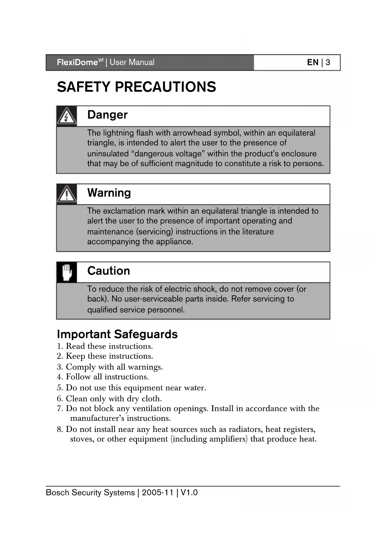
The lightning flash with arrowhead symbol, within an equilateral triangle, is intended to alert the user to the presence of uninsulated "dangerous voltage" within the product's enclosure that may be of sufficient magnitude to constitute a risk to persons.

Warning
The exclamation mark within an equilateral triangle is intended to alert the user to the presence of important operating and maintenance (servicing) instructions in the literature accompanying the appliance.

Caution
To reduce the risk of electric shock, do not remove cover (or back). No user-serviceable parts inside. Refer servicing to qualified service personnel.
Important Safeguards
- Read these instructions.
- Keep these instructions.
- Comply with all warnings.
- Follow all instructions.
- Do not use this equipment near water.
- Clean only with dry cloth.
- Do not block any ventilation openings. Install in accordance with the manufacturer's instructions.
-
Do not install near any heat sources such as radiators, heat registers, stoves, or other equipment (including amplifiers) that produce heat.
-
Do not defeat the safety purpose of the polarized or grounding-type plug. A polarized plug has two blades with one wider than the other. A grounding type plug has two blades and a third grounding prong. Both the wide blade and the third prong are provided for your safety. If the supplied plug does not fit into your outlet, consult an electrician for advice.
- Protect the power cord from being walked on or pinched particularly at plugs, convenience receptacles, and the point where they exit from the equipment.
- Only use attachments/accessories specified by the manufacturer.
- Unplug this equipment during lightning storms or when unused for long periods of time.
- Refer all servicing to qualified service personnel. Servicing is required when the equipment has been damaged in any way, such as when power supply cord or plug is damaged, liquid has been spilled or objects have fallen into the equipment, the equipment has been exposed to rain or moisture, does not operate normally, or has been dropped.
- An all-pole mains switch with a contact separation of at least 3mm in each pole shall be incorporated in the electrical installation of the building.

Warning
To reduce the risk of fire or electric shock, this apparatus should not be exposed to rain or moisture and objects filled with liquids, such as vases, should not be placed on this apparatus.

Caution
The Low Voltage power supply unit must comply with EN/UL 60950. The power supply must be a SELV-LPS unit or a SELV -Class 2 unit (Safety Extra Low Voltage - Limited Power Source).
FCC Information
This equipment has been tested and found to comply with the limits for a Class B digital device, pursuant to part 15 of the FCC Rules. These limits are designed to provide reasonable protection against harmful interference in a residential installation. This equipment generates, uses and can radiate radio frequency energy and, if not installed and used in accordance with the instructions, may cause harmful interference to radio communications. However, there is no guarantee that interference will not occur in a particular installation. If this equipment does cause harmful interference to radio or television reception, which can be determined by turning the equipment off and on, the user is encouraged to try to correct the interference by one or more of the following measures:
- Reorient or relocate the receiving antenna.
- Increase the separation between the equipment and receiver.
- Connect the equipment into an outlet on a circuit different from that to which the receiver is connected.
- Consult the dealer or an experienced radio/ TV technician for help.
Note
Any change or modification of the equipment not expressly approved by Bosch could void the user's authority to operate the equipment. For additional information or to speak to a representative, please contact the Bosch Security Systems location nearest to you or visit our web site at www.boschsecuritysystems.com
Introduction
The FlexiDome ^VF camera is a small, discreet, surveillance dome camera containing a high-performance 1/3-inch CCD camera with integral varifocal lens. The integrated unit is mounted to an electrical box or to a wall or ceiling. The sturdy construction of the enclosure and polycarbon dome protect the camera module from damage.
The camera incorporates advanced digital signal processing for outstanding picture performance under all lighting conditions. The FlexiDome ^VF camera is easy to install and ready to use, and offers the best solution for demanding indoor scene conditions.
Features include:
- Polycarbonate dome
- 540 TVL resolution for color cameras
N i g h t S e n s e - On-screen setup menu
- Bilinx™ bi-directional coaxial communications
The FlexiDomeVF camera is available in color and monochrome versions.
Type number overview
FlexiDomevF Monochrome
| Type number VDM-345V03-10 | VDM-345V04-10 | VDM-345V03-20 | VDM-345V04-20 | |
| Lens Varifocal | 2.6-6 mmF1.4-360 | Varifocal4-9 mmF1.6-360 | Varifocal2.6-6 mmF1.4-360 | Varifocal4-9 mmF1.6-360 |
| Standard CCIR EIA | ||||
| Supply voltage 24 Vac, 50Hz or 12 Vdc 24 Vac, 60Hz or 12 Vdc | ||||
| CCD type 1/3" | ||||
FlexiDomevF Color
| Type number VDC-445V03-10 | VDC-445V04-10 | VDC-445V03-20 | VDC-445V04-20 | |
| Lens Varifocal | 2.6-6 mmF1.4-360 | Varifocal4-9 mmF1.6-360 | Varifocal2.6-6 mmF1.4-360 | Varifocal4-9 mmF1.6-360 |
| Standard Color PAL Color NTSC | ||||
| Supply voltage 24 Vac, 50Hz or 12 Vdc 24 Vac, 60Hz or 12 Vdc | ||||
| CCD format 1/3" | ||||
Unpacking
Unpack carefully and handle the equipment with care. The packaging contains:
- Integrated FlexiDome camera
- Mounting hardware kit
Installation manual
Note
If equipment appears to have been damaged during shipment, repack it in the original packaging and notify the shipping agent or supplier.

Caution
Installation should only be performed by qualified service personnel in accordance with the National Electrical Code or applicable local codes.
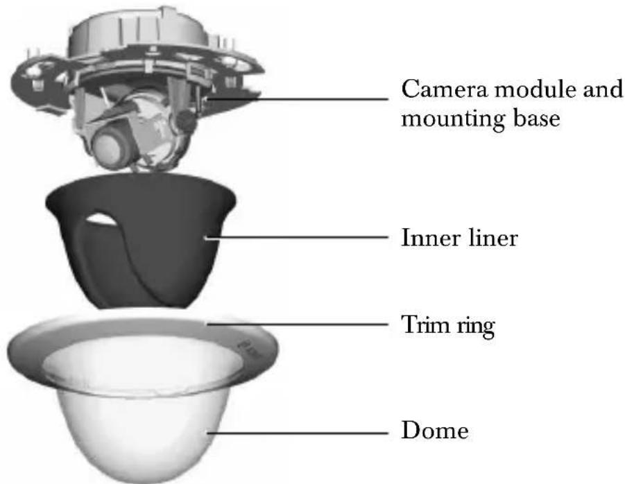
Disassembly
The camera/housing unit consists of the following parts:

Caution
The camera module is a sensitive device and must be handled carefully. Do not drop when disassembling the unit.
To disassemble the unit proceed as follows:
- Rotate the trim ring counterclockwise to release it from its bayonet on the camera base.
- Remove the trim ring with dome.
- Remove the inner liner by pulling it off of the base.
Mounting the unit
The unit may be mounted in several different ways depending on the type of surface, whether an electrical box is used and whether the connection is via the rear or the side (surface mounted).

Caution
Installation should only be performed by qualified service personnel in accordance with the National Electrical Code or applicable local codes.
If the unit is surface mounted, use the separately available surface mounting box (VDA-445SMB) and mount the unit onto this base.
Tips
-
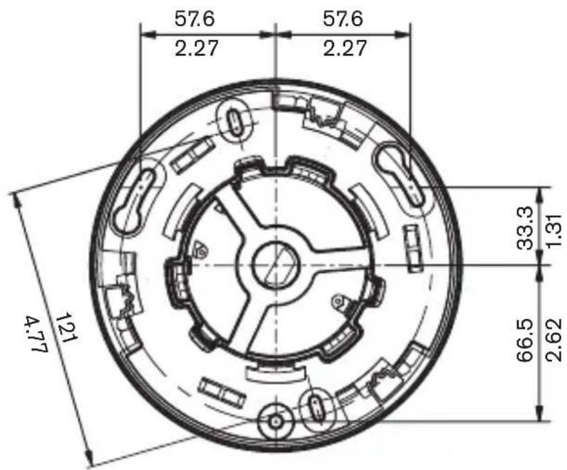
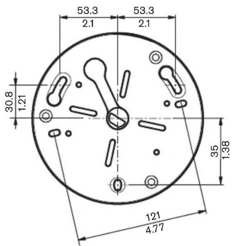
Refer to the dimensions drawing to find the exact position of the screw holes and the entry hole for the wires.
-
Partially screw in two screws for the keyholes and use them to temporarily hang the camera while the connections are made.
The following figures show the different ways of mounting the unit.
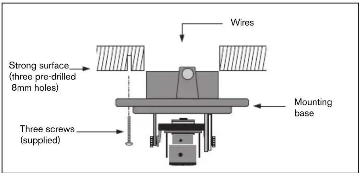
Figure 1 Rear connection - hollow surface
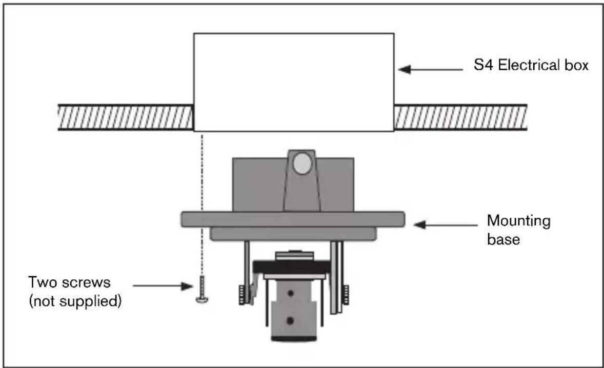
Figure 2 Connection to an electrical box (4S)
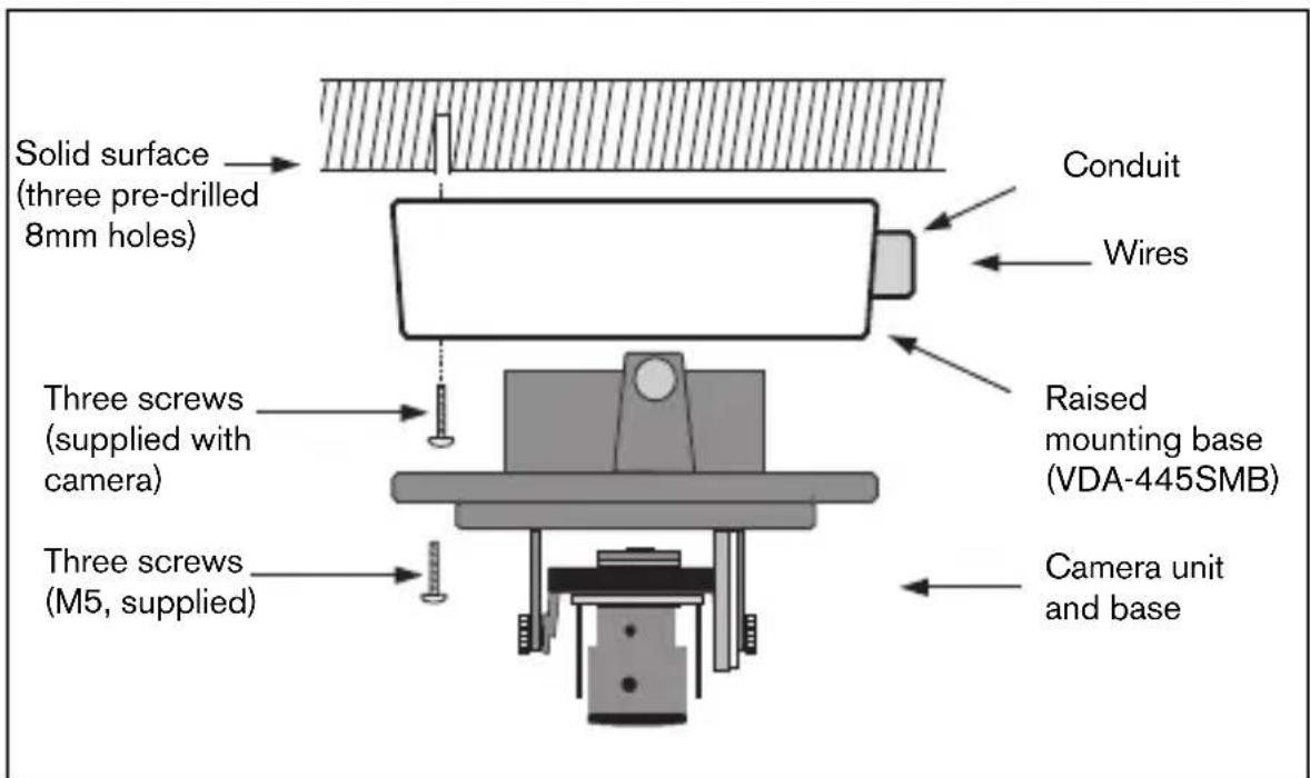
Figure 3 Surface mounting - side connection
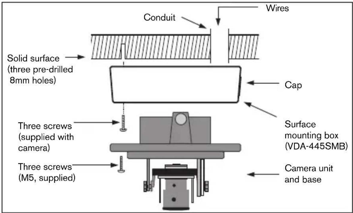
Figure 4 Surface mounting - rear connection
Raised mounting
When using the surface mounting box:
- With a side connection, remove the cap covering the side entrance.
With a rear connection, leave the cap in place. - Attach the conduit to the mounting base.
- Make the connection inside the mounting case.
Connection and set-up
Power and video connections
The wiring harness has a BNC connector to accept the video coax cable (with male BNC connector) and two stripped low voltage power wires for connection to a power connector. (A UTP adapter is available as an accessory to allow a UTP video cable to be connected to the BNC connector.)

Caution
Before proceeding, be sure to disconnect the power from the cable to be installed into the unit. Be sure that the unit is of the proper voltage type for the line power being used.
The easiest way to connect the low voltage power lines and the video connection is as follows:
- Bring the building connections through the surface wire hole so that they hang clear.
- Partially insert two screws into the pre-drilled holes.
- Using the keyholes, hang the mounting base on one screw temporarily and tilt the base slightly to gain access to the cable connections.
- Connect the BNC connector of the camera module to the video coax cable.
- Connect the stripped power wires to the power supply connector.
Note
For a DC supply the polarity is not important. For an AC supply try to maintain a consistent wiring polarity in multiple camera systems to help avoid rolling when switching.
- Push the connections back through the surface wire hole.
- Secure the mounting base to the surface with three screws.
Setting up the camera
You can connect a monitor to the miniature 2.5mm jack socket on the printed circuit board to help set up the camera. This socket provides a composite video signal (with sync). An optional cable (code number S1460) is available for making this connection.
Camera positioning
The physical default position of the camera is that the top of the image corresponds to the indication TOP.

Caution
The CCD image sensors are highly sensitive and require special care for proper performance and extended lifetime. Do not expose them to direct sunlight or bright spotlights in operating and non-operating conditions. Avoid bright lights in the field of view of the camera.
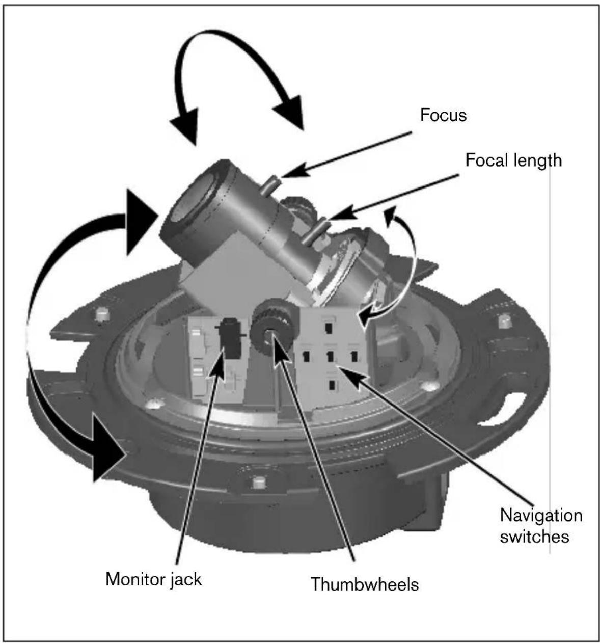
The camera module position can be adjusted along three axes. When adjusting the camera position ensure that the picture display on the monitor is level. Set the camera to the desired position by performing the following steps:
- For horizontal adjustment (pan), rotate the camera module in the base. Do not rotate more than 360^ .
- For vertical adjustment (tilt), loosen thumbscrews, position camera, then gently tighten thumbscrews to secure camera.
- To obtain a horizontal horizon (for tilted ceilings or sidewall mounting), rotate the base of the lens as necessary to align the picture shown on the monitor. Do not rotate more than 340^ .
Focal length and focus
- To set the field of view of the varifocal lens, loosen the focal length screw and turn the mechanism until the required view is displayed on the monitor. (Image goes out of focus.)
- Focus the image on the monitor by loosening the focus screw and turning the mechanism until the image is in focus.
- Readjust the focal length if necessary.
- Repeat these two adjustments until the desired view is in focus.
- Tighten both screws.
Verify that the image stays in focus when the dome is held in place. Refocus if necessary.
Closing the unit
When the camera position is set and all adjustments have been made, close the unit.
- Place the inner liner in position aligning its fin with the bracket on the base.
- Place the trim ring with dome onto the base. (If necessary clean its surface with a soft cloth.)
Fix the trim ring onto the camera base by rotating clockwise.
Advanced Set-up
The FlexiDome ^VF normally provides an optimal picture without the need for further adjustments. However, advanced set-up options are available for getting the best results from the camera under special circumstances. There are two menus; a Main menu and an Installer menu.
The Main menu allows you to select and set-up the picture enhancement functions for each mode. If you are not happy with your changes, you can always recall the default values for the mode.
The camera also has an Installer menu in which the installation settings can be set.
The Main and Installer menus have functions that can be selected directly or submenus for more detailed set-up.
Accessing and navigating menus
Five keys are used for navigating through the various menus. To access the set-up menus, press the menu/select key (center). The main menu appears on the OSD. Use the arrow keys for navigation.
When the Bilinx^TM communications link is active, the buttons on the camera are disabled. You can also set up Bilinx^TM so that the camera buttons remain disabled even when Bilinx^TM is not actively controlling the camera. This prevents unauthorized change of the camera settings.
Menu Structure
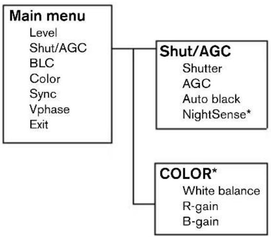
* Only for the Color version of the camera.
Hints for menu navigation
How to use the 5 keys
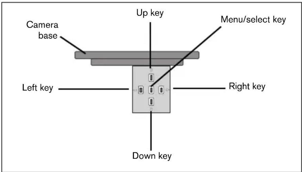
- Press the menu/select key to access the menus or to move to the next or previous menu.
- Press the menu/select key for approximately 1.5 seconds to open the Installer menu.
- Use the up or down keys to scroll up or down through a menu.
- Use the left or right keys to move through options or to set parameters.
- When in a menu, quickly pressing the menu/select key twice restores the selected item to its factory default.
- To close all menus at once from any menu, select the Exit item and hold down the menu/select key until the menu display disappears.
Main menu
| Function Selection Description | ||
| LEVEL -15 - 0 - +15 Adjusts the video output level | ||
| SHUT/AGC | Select submenu | Select to access the Shutter / Automatic Gain Control menu |
| BLC ON, OFF When ON, the video | level is optimized for the selected area of the image. Parts outside this area may be underexposed or overexposed (this is normal). | |
| COLOR* ATV | ATB HOLD | Select to access the color menu. |
| Select submenu | ||
| SYNC LINE LOCK | INTERNAL | Select LINE LOCK to synchronize with the power supply frequency. Select INTERNAL for use with internal synchronization (automatically selected with DC supply). |
| VPHASE | 0, 2, ... 358° | Adjusts the vertical phase offset (when in LINE LOCK mode and a valid power supply frequency is detected). |
| EXIT Exit the menu | ||
- Only in color version of camera. If a color camera is in monochrome mode, all color related menu items are disabled and cannot be accessed.
Shutter/AGC submenu
| Function | Selection | Description |
| SHUTTER AES, FL • AES - auto-shutter - the camera automatically sets the optimum shutter speed •FL - flickerless mode avoids interference from light sources (recommended for use with video iris or DC iris lenses only) | ||
| AGC | ON/OFF | Automatic gain control |
| AUTOBLACK | ON/OFF | Autoback automatically increases the visibility of details. |
| NIGHTSENSE* | AUTO FORCED OFF | Nightsense™ extends the low-light performance of the camera. •In AUTO mode, the camera automatically inches to monochrome in low-light conditions. •In FORCED mode, the camera remains in high-sensitivity monochrome operation. |
| EXIT Exit the menu | ||
- Only in color version of camera.
Note
If NightSense™ is active, some noise or spots may appear in the picture. This is normal camera behavior.
If a color camera is in monochrome mode, all color related menu items are disabled and cannot be accessed.
Color submenu*
| Function Selection Description | ||
| WHITE BALANCE | ATW AWB HOLD | •ATW: Auto tracking white balance allows the camera to constantly adjust for optimal color reproduction. •AWB HOLD: Puts the ATW on hold and saves the color settings. |
| RED gain** | -5 - 0 - +5 | Offset factory white point alignment (reducing red introduces more cyan). |
| BLUE gain** | -5 - 0 - +5 Offset factory | ry white point alignment (reducing blue introduces more yellow). |
| EXIT Exit the | menu | |
- Only in color version of camera.
** It is only necessary to change the white point offset for special scene conditions.
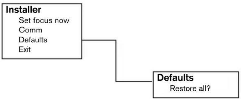
Installer Settings
Install menu
| Function Selection Description | ||
| SET FOCUS NOW | Forces the lens to fully open the iris. Adjust the lens focus now. | |
| COMM ON, | OFF Bilinx commun | cation ON/OFF |
| DEFAULTS | Select submenu Return | rn all settings for all modes to factory defaults |
| EXIT Exit the | menu | |
Adjustment procedure DC-iris Lens:
- Unlock the focus locking screw.
- SET BACK FOCUS NOW is highlighted in the menu.
- Turn the focus adjustment as required.
- Lock the focus locking screw.
- Exit the menu selection.
Defaults submenu
| Function Selection Description | ||
| ALL DEFAULTS | Select to restore the factory defaults. A confirmation screen appears. Allow 5 seconds for the camera to optimize the picture after a mode reset. | |
| EXIT Exit the | menu | |
Camera control communication
This camera is equipped with a coaxial communications transceiver. In combination with VP-CFGSFT, the camera can be adjusted from the head-end side of the coaxial cable. All menus can be accessed remotely giving full control of the camera. With this communication it is also possible to disable the local keys on the camera. To avoid loss of communication on an installed camera, the Communication ON/OFF selection is not available while using remote control. This function can only be accessed with the camera buttons.
Technical specification
| Type number VDC-445V0x-10 | VDC-445V0x-20 | VDC-345V0x-10 | VDC-345V0x-20 | |
| Standard PAL NTSC CCIR EIA | ||||
| Active pixels 752x582 768x492 752x582 768x492 | ||||
| Min illumination <1.0 lux<0.4 lux (NightSense On) | <0.2 lux | |||
| Resolution 540 TVL 570 TVL | ||||
| Rated supplyvoltage | 24 VAC or 12 VDC12-28 VAC (50/60 Hz)11-36 VDC | |||
All versions
| Imager | Interline CCD |
| SNR | >50 dB |
| Video output | 1 Vpp, 75 Ohm |
| Synchronization | Internal or Line Lock selectable |
| Shutter | AES (1/60 (1/50) to 1/100000), Flickerless selectable |
| Auto black | On, Off selectable |
| AGC | AGC On (20 dB) or Off selectable |
| Contour | Sharpness enhancement |
| BLC | BLC On or Off selectable |
| White balance* Automatic | 2500 - 9000K (with AWB hold mode) |
| Lens | Integrated Varifocal with DC iris |
| Power consumption | <5 W |
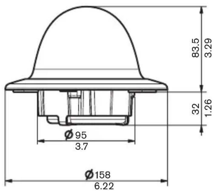
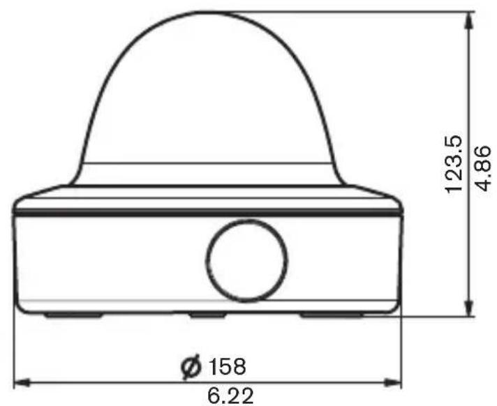
| Dimensions | 58 x 66 x 122 mm (HxWxL) |
| Weight | 550g |
| Operating temperature | -10° to 45°C |
| Controls | OSD with softkey operation |
Dimensions (mm/inches)
Dimensions with surface mount box (mm/inch)
Accessories
Power transformers
- TC1334 120VAC, 60Hz - 24VAC, 30VA
- TC120PS 120VAC, 60Hz - 15VDC, 9VA
- TC220PSX-24 220-240VAC, 50/60Hz - 24VAC, 30VA
- TC220PS 220-240VAC, 50/60Hz - 15VDC, 9VA
Interface box:
- VP-CFGSFT Bilinx™ communication interface box and software
CONSIGNES DE SECURITÉ

Danger
External camerabesturing
Sottomenu Shutter/AGC
© 2005 Bosch Security Systems B.V.
Subject to change. Printed in Portugal.
3122 165 xxxxx
- FR
- ES
- Warning
- Caution
- Important Safeguards
- FCC Information
- Note
- Introduction
- Type number overview
- Unpacking
- Disassembly
- Mounting the unit
- Tips
- Raised mounting
- Connection and set-up
- Power and video connections
- Setting up the camera
- Camera positioning
- Focal length and focus
- Closing the unit
- Advanced Set-up
- Accessing and navigating menus
- Menu Structure
- Hints for menu navigation
- How to use the 5 keys
- Main menu
- Shutter/AGC submenu
- Installer Settings
- Install menu
- Defaults submenu
- Camera control communication
- Technical specification
- All versions
- Dimensions (mm/inches)
- Dimensions with surface mount box (mm/inch)
- Accessories
- Power transformers
- Interface box:
- CONSIGNES DE SECURITÉ
- Danger
- External camerabesturing
- Sottomenu Shutter/AGC
Brand : BOSCH
Model : VDC455V0410
Category : Surveillance Camera