
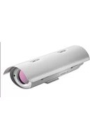
MIC IP FUSION 9000i - Surveillance Camera BOSCH - Free user manual and instructions
Find the device manual for free MIC IP FUSION 9000i BOSCH in PDF.


| Product Type | IP Surveillance Camera |
| Model | MIC IP FUSION 9000i |
| Brand | Bosch |
| Dimensions (H x W x D) | Approx. 350 x 200 x 200 mm |
| Weight | Approx. 5.5 kg |
| Power Supply | PoE+ (IEEE 802.3at) or 24 VAC |
| Power Consumption | Max. 25 W |
| Image Sensor | 1/1.8-inch CMOS |
| Resolution | Up to 4K (3840 x 2160) |
| Lens | Motorized zoom, 4.3-129mm (30x optical zoom) |
| Field of View | Wide: 63°; Tele: 2.3° |
| Pan / Tilt / Zoom (PTZ) | Pan: 360° endless; Tilt: -90° to +90°; Zoom: 30x optical |
| Night Vision | Yes, infrared up to 150 m |
| Weatherproof Rating | IP66, IK10 |
| Operating Temperature | -40°C to +60°C |
| Video Compression | H.265, H.264, M-JPEG |
| Network Interface | 10/100/1000 Base-T Ethernet |
| Audio | Two-way audio, built-in microphone |
| Alarm Input/Output | 2 alarm inputs, 1 relay output |
| Storage | MicroSD card slot (up to 512 GB), local storage |
| Maintenance & Cleaning | Clean lens with soft cloth; avoid solvents. Check seals periodically. |
| Safety & Compliance | CE, FCC, UL, RoHS |
| Spare Parts & Repairability | Spare parts available through Bosch service centers; professional repair recommended. |
| Warranty | 2 years limited warranty |
Frequently Asked Questions - MIC IP FUSION 9000i BOSCH
User questions about MIC IP FUSION 9000i BOSCH
0 question about this device. Answer the ones you know or ask your own.
Ask a new question about this device
Download the instructions for your Surveillance Camera in PDF format for free! Find your manual MIC IP FUSION 9000i - BOSCH and take your electronic device back in hand. On this page are published all the documents necessary for the use of your device. MIC IP FUSION 9000i by BOSCH.
USER MANUAL MIC IP FUSION 9000i BOSCH
en
Installation Manual
Table of Contents
1 Safety 4
1.1 About this Manual 4
1.2 Legal Information 4
1.3 Safety Precautions 5
1.4 Important Safety Instructions 6
1.5 Important Notices 7
1.6 Use Latest Software 10
1.7 Customer Support and Service 10
2 Introduction 11
2.1 Additional Products Required 11
2.2 Additional Tools 11
2.3 Establishing the Connection 11
2.4 Password protection in camera 12
| 3 | Product Description 14 | |
| 4 | Installation Overview | 15 |
| 5 | Mounting | 17 |
5.1 Mounting Location and Orientation Options 17
5.2 Mounting Options 19
5.3 Mounting Bracket Options 21
5.4 Considerations for Mounting the Camera in Inverted Orientation 24
6 Installing the camera outdoors 27
7 (Optional) Configuration Programming in the Shipping Box 30
8 (Optional) Configuration Programming on a Temporary Table-top Stand 31
9 Installing a MIC Camera on a Hinged DCA 32
10 (Optional) Installing a Sunshield 36
11 Connection 38
11.1 About Camera Power and Control 38
11.2 Power Source Options 38
11.3 Ethernet Connections 39
11.4 Camera Connections 40
11.5 Connect the Camera to the Network 40
12 Typical System Configurations 42
13 Troubleshooting 43
14 Maintenance 46
14.1 Replacing a wiper assembly 47
15 Decommissioning 55
15.1 Transfer 55
15.2 Disposal 55
16 Technical data 56
17 Support services and Bosch Academy 57
1 Safety
1.1 About this Manual
This manual has been compiled with great care and the information it contains has been thoroughly verified. The text was complete and correct at the time of printing. Because of the ongoing development of products, the content of the manual may change without notice. Bosch Security Systems accepts no liability for damage resulting directly or indirectly from faults, incompleteness, or discrepancies between the manual and the product described.
1.2 Legal Information
Copyright
This manual is the intellectual property of Bosch Security Systems, and is protected by copyright. All rights reserved.
Trademarks
All hardware and software product names used in this document are likely to be registered trademarks and must be treated accordingly.
1.3 Safety Precautions
In this manual, the following symbols and notations are used to draw attention to special situations:

Danger!
High risk: This symbol indicates an imminently hazardous situation such as “Dangerous Voltage” inside the product. If not avoided, this will result in an electrical shock, serious bodily injury, or death.

Warning!
Medium risk: Indicates a potentially hazardous situation. If not avoided, this may result in minor or moderate injury.

Caution!
Low risk: Indicates a potentially hazardous situation. If not avoided, this may result in property damage or risk of damage to the unit.

Notice!
This symbol indicates information or a company policy that relates directly or indirectly to the safety of personnel or protection of property.
1.4 Important Safety Instructions
| When transporting, take extra care to protect the wiper and the camera window(s). | |
| Caution!Installation must be made by qualified personnel and conform to ANSI/NFPA 70 (the National Electrical Code* (NEC)), Canadian Electrical Code, Part I (also called CE Code or CSA C22.1), and all applicable local codes. Bosch Security Systems accepts no liability for any damages or losses caused by incorrect or improper installation. | |
| Warning!INSTALL EXTERNAL INTERCONNECTING CABLES IN ACCORDANCE TO NEC, ANSI/NFPA70 (FOR US APPLICATION) AND CANADIAN ELECTRICAL CODE, PART I, CSA C22.1 (FOR CAN APPLICATION) AND IN ACCORDANCE TO LOCAL COUNTRY CODES FOR ALL OTHER COUNTRIES. BRANCH CIRCUIT PROTECTION INCORPORATING A 20 A, 2-POLE LISTED CIRCUIT BREAKER OR BRANCH RATED FUSES ARE REQUIRED AS PART OF THE BUILDING INSTALLATION. A READILY ACCESSIBLE 2-POLE DISCONNECT DEVICE WITH A CONTACT SEPARATION OF AT LEAST 3 mm MUST BE INCORPORATED. | |
| Warning!ROUTING OF EXTERNAL WIRING MUST BE DONE THROUGH A PERMANENTLY EARTHED LIQUID TIGHT METAL CONDUIT. | |
| Notice!Outdoor installationFor details about the proper configuration for installing your camera outdoors with surge and lightning protection, refer to the chapter “Installing the camera outdoors, page 27.” | |
| - Ensure that the unit case is properly earthed. If the product is at risk of being struck by lightning, ensure that earth bonding connections are made correctly to the mounting of the base of the unit. | |
| Notice!Bosch recommends the use of surge/lightning suppression devices (sourced locally) to protect network and power cables and the camera installation site. Refer to NFPA 780, Class 1 & 2, UL96A, or the equivalent code appropriate for your country/region, and to local building codes. Refer also to the installation instructions of each device (midspan, camera, and surge suppression device installed where the cable enters the building). | |
| Notice!Ancillary power (UPS) requiredTo meet the Mains Supply Voltage Dips and Short Interruptions requirements per EN 50130-4 Alarm Standard, ancillary equipment (for example, an Uninterruptible Power Supply (UPS)) is necessary. The UPS must have a Transfer time between 2-6 ms and Backup Runtime of greater than 5 seconds for the power level as specified on the product data sheet. | |
| Warning!THE CAMERA MUST BE MOUNTED DIRECTLY AND PERMANENTLY TO A NON-COMBUSTIBLE SURFACE.- Make sure that the installation conditions comply with the specified stresses of vibration and shock as mentioned in the datasheet.- Use on mobile platforms is not recommended. Refer to the warranty statement for more information.- Use common-sense safety precautions, especially in situations where there could be risk of injury if any part of the assembly becomes detached and falls. Bosch recommends using the hinged DCA, which allows installers to “hang” the MIC camera temporarily on the DCA to make electrical connections, before bolting the camera to the DCA. | |
 | Notice!To maintain the Type 6P rating when the camera is mounted to a MIC-DCA, installers must make sure that the user-supplied cable glands or conduit connections have Type 6P ratings. |
 | Warning!Do not manually back drive the cameraThe motor/gear head combinations used in the MIC cameras were designed to provide smooth pan/tilt movement of the camera during powered operation. The gear heads were not specifically designed to be manually “back-driven” under any circumstance.Although it might be possible to do so on unpowered units, there is no guarantee that “back-driving” will be possible on every unit. Some units may even enter a “locked-up” mechanical state.If the camera becomes “locked-up,” simply apply power to the camera. The pan/tilt functions of the camera should now operate properly. |
 | Warning!Moving parts!Moving parts may result in risk of injury, therefore, the device should be mounted so that it is accessible only to the technician/installer. |
 | Notice!Risk of injury or damageTo prevent injury to your hands or damage to the wiper, do not touch the wiper with your hands, especially when the wiper is moving. |
| - Do not open the camera unit. Doing so will invalidate the warranty.- Do not point the camera at the sun. Bosch Security Systems will not be liable for any damage to cameras that have been pointed directly at the sun. |
1.5 Important Notices


combination to avoid injury from tip-over. Quick stops, excessive force, or uneven surfaces may cause the cart/unit combination to overturn. Mount the unit per the installation instructions.
Adjustment of controls - Adjust only those controls specified in the operating instructions. Improper adjustment of other controls may cause damage to the unit.
All-pole power switch - Incorporate an all-pole power switch, with a contact separation of at least 3 mm, into the electrical installation of the building. If the camera requires service, use this all-pole switch as the main disconnect device for switching off the voltage to the unit.
Camera signal - Protect the cable with a primary protector if the camera signal is beyond 140 feet, in accordance with NEC800 (CEC Section 60).
Environmental statement - Bosch has a strong commitment towards the environment. This device has been designed to respect the environment as much as possible.
Electrostatic-sensitive device - Use proper ESD safety precautions when handling the camera to avoid electrostatic discharge.
Fuse rating - For security protection of the device, the branch circuit protection must be secured with a maximum fuse rating of 16A. This must be in accordance with NEC800 (CEC Section 60).
Grounding:
- Connect outdoor equipment to the unit's inputs only after this unit has had its ground terminal connected properly to a ground source.
- Disconnect the unit's input connectors from outdoor equipment before disconnecting the grounding terminal.
- Follow proper safety precautions such as grounding for any outdoor device connected to this unit.
U.S.A. models only - Section 810 of the National Electrical Code, ANSI/NFPA No.70, provides information regarding proper grounding of the mount and supporting structure, size of grounding conductors, location of discharge unit, connection to grounding electrodes, and requirements for the grounding electrode.
Refer to the chapter "Installing the camera outdoors, page 27" in the installation manual for more information on outdoor installations.
Heat sources - Do not install unit near any heat sources such as radiators, heaters, or other equipment (including amplifiers) that produce heat.
Moving - Before moving the unit, disconnect both the 24 VAC connection and the Ethernet cable connection (if using PoE).
Outdoor signals - The installation for outdoor signals, especially regarding clearance from power and lightning conductors and transient protection, must be in accordance with NEC725 and NEC800 (CEC Rule 16-224 and CEC Section 60).
Refer to the chapter "Installing the camera outdoors, page 27" in the installation manual for more information on outdoor installations.
Permanently connected equipment - Incorporate a readily accessible disconnect device in the building installation wiring.
Power lines · Do not locate the camera near overhead power lines, power circuits, or electrical lights, nor where it may contact such power lines, circuits, or lights.
Servicing · Do not attempt to service this device yourself. Refer all servicing to qualified service personnel.
This device has no user-serviceable internal parts.
FCC information
Intentional or unintentional modifications, not expressly approved by the party responsible for compliance, shall not be made. Any such modifications could void the user's authority to operate the equipment.

Notice!
This is a class A product. In a domestic environment this product may cause radio interference, in which case the user may be required to take adequate measures.
FCC suppliers Declaration of Conformity
MIC IP fusion 9000i High-definition PTZ camera with thermal and visual imagers
Responsible party
Bosch Security Systems, LLC
130 Perinton Parkway
14450 Fairport, NY, USA
www.boschsecurity.us
UL Disclaimer
Underwriter Laboratories Inc. ("UL") has not tested the performance or reliability of the security or signaling aspects of this product. UL has only tested fire, shock and/or casualty hazards as outlined in Standard(s) for Safety for Information Technology Equipment,
UL 62368-1. UL Certification does not cover the performance or reliability of the security or signaling aspects of this product.
UL MAKES NO REPRESENTATIONS, WARRANTIES, OR CERTIFICATIONS WHATSOEVER REGARDING THE PERFORMANCE OR RELIABILITY OF ANY SECURITY OR SIGNALING-RELATED FUNCTIONS OF THIS PRODUCT.
1.6 Use latest software
Before operating the device for the first time, make sure that you install the latest applicable release of your software version. For consistent functionality, compatibility, performance, and security, regularly update the software throughout the operational life of the device. Follow the instructions in the product documentation regarding software updates.
The following links provide more information:
– General information: https://www.boschsecurity.com/xc/en/support/product-security/ - Security advisories, that is a list of identified vulnerabilities and proposed solutions: https://www.boschsecurity.com/xc/en/support/product-security/security-advisories.html Bosch assumes no liability whatsoever for any damage caused by operating its products with outdated software components.

Notice!
Bosch strongly recommends upgrading to the latest firmware for the best possible functionality, compatibility, performance and security.
Check http://downloadstore.boschsecurity.com/ regularly to see if there is a new firmware version available.
1.7 Customer Support and Service
If this unit needs service, contact the nearest Bosch Security Systems Service Center for authorization to return and shipping instructions.
USA and Canada
Telephone: 800-289-0096, option 5
Fax: 800-366-1329
Email: repair@us.bosch.com
Customer Service
Telephone: 800-289-0096, option 3
Fax: 800-315-0470
Email: orders@us.bosch.com
Technical Support
Telephone: 800-289-0096, option 4
Fax: 800-315-0470
Email: technical.support@us.bosch.com
Europe, Middle East, Africa, and Asia Pacific Regions
Contact your local distributor or Bosch sales office. Use this link: https://
www.boschsecurity.com/xc/en/where-to-buy/
More Information
For more information, please contact the nearest Bosch Security Systems location or visit www.boschsecurity.com.
2 Introduction
- This equipment should be unpacked and handled with care. Check the exterior of the packaging for visible damage. If an item appears to have been damaged in shipment, notify the shipper immediately.
- Verify that all the parts listed in the Parts List below are included. If any items are missing, notify your Sales or Customer Service Representative from Bosch Security Systems.
- Do not use this product if any component appears to be damaged. Please contact Bosch Security Systems in the event of damaged goods.
- The original packing carton (if undamaged) is the safest container in which to transport the unit and must be used if returning the unit for service. Save it for possible future use.

Caution!
Take extra care lifting or moving MIC cameras because of their weight.
The MIC packaging is designed:
- to allow installers to configure the camera inside the shipping box.
- to provide a temporary table-top or desk-top stand.
2.1 Additional Products Required
| Quantity Component | |
| 100 m maximum | Ethernet cable (Cat5e or better) |
| * Power cable (24 VAC) | |
| * Alarm wiring as needed | |
| * Audio wiring as needed | |
| 1 Full SD card. Recommended: industrial SD cards from Western Digital (sold separately by Bosch) | |
* Refer to the chapter Preparing Wiring in the installation manual.
2.2 Additional Tools
1 Phillips-head screwdriver to secure the ground lug of the camera 1 Adjustable wrench or socket set to secure the base of the camera to mounting accessories
2.3 Establishing the connection
The unit must have a valid IP address and a compatible subnet mask to operate on your network. By default, DHCP is pre-set at the factory to On and so your DHCP server assigns an IP address. With no DHCP server the default address is 192.168.0.1
The Project Assistant app or Configuration Manager (version 7.50 or higher) can be used to find the IP address. Download the software from https://downloadstore.boschsecurity.com:
- Start the web browser.
- Enter the IP address of the device as the URL.
- During the initial installation, confirm any security questions that show.
If a RADIUS server is used for network access control (802.1x authentication), you must configure the device before the device can communicate with the network.
To configure the device, connect it directly to a computer using a network cable and then set the service-level password.
Note:
If you cannot connect, the unit may have reached its maximum number of connections.
Depending on the device and network configuration, each unit can have up to 50 web browser connections, or up to 100 connections via Bosch Video Client or BVMS.
2.4 Password protection in camera
The device is password-protected. The first time that any user accesses the device, the device will prompt the user to set a password at the service level.
The camera requires a strong password. Follow the prompts in the dialog box, which specifies what is required. The system measures the strength of the password that you enter.
Make sure the password obeys these conditions:
- 8 to 19 characters in length – Upper and lower case letters
- Minimum of 1 digit
- Minimum of 1 special character
These special characters are not allowed: '@', '&', '<', '>', ':', '+'
When you use Configuration Manager to access your device for the first time, you must set the initial password of the device in Configuration Manager. The Users section (General > Unit Access > Users) displays the message, "Before you can use this device you have to secure it with an initial password."
Note: After you set the initial password, a "lock" icon appears next to the device name in the Devices list in Configuration Manager.
You can also launch the device webpage directly. In the device webpage, an initial password page appears, displaying input fields and a password strength gauge.
Enter the user name ("service") and a password in the appropriate fields. Refer to the section
User Management for more information.
After a service-level password is set for the device, the device displays a dialog box that prompts users to enter the user name (“service”) and the service-level password every time that they access the device.
- Fill in the fields User name and Password.
- Click OK. If the password is correct, the desired page appears.
Note: New releases of software may require you to set a new and stronger password.
Notices for local certification - Korea

Notice!
Use the internal USB-C port only for administration purposes.

Notice!
This is an industrial product and has only been tested for industrial use. Do not use this product for residential or home monitoring purposes.

Notice!
This product does not include an amplifier. For audio output, use a built-in amplifier speaker.
3 Product Description
Make sure that the installation conditions comply with the specified stresses of vibration and shock as mentioned in the datasheet.
The MIC IP fusion 9000i camera is a day/night, IP PTZ camera with dual optical/thermal imagers. Ruggedized and weatherproof, the camera offers a reliable, robust, and high-quality surveillance solution for extreme security applications.
A long-life silicone wiper blade mounted on a spring-loaded arm is standard on all MIC cameras.
The following table identifies the optional accessories for MIC cameras. Refer to the datasheets of each accessory for details. Some accessories may not be available in all regions.
| Accessories Description | |||
| MIC-DCA-H- MIC-DCA-HB- MIC-DCA-HW- MIC-DCA-HG- MIC-DCA-HBA- MIC-DCA-HWA- MIC-DCA-HGA | Hinged Deep Conduit Adapter in Black White Grey Black with M25 to 3⁄4” adapter White with M25 to 3⁄4” adapter Grey with M25 to 3⁄4” adapter | MIC-SCA- MIC-SCA-BD- MIC-SCA-WD- MIC-SCA-MG | Shallow Conduit Adapter in Black White Grey |
| MIC-CMB- MIC-CMB-BD- MIC-CMB-WD- MIC-CMB-MG | Corner Mount Bracket in Black White Grey | MIC-SPR- MIC-SPR-BD- MIC-SPR-WD- MIC-SPR-MG | Spreader Plate in Black White Grey |
| MIC-WMB- MIC-WMB-BD- MIC-WMB-WD- MIC-WMB-MG | Wall Mount Bracket in Black White Grey | MIC-PMB Pole Mount Bracket (stainless steel only) | |
| NPD-9501A 95 W midspan MIC-WKT-IR Washer Kit | |||
| VG4-A-PSU1VG4-A-PSU2 | 24 VAC (96 VA) power supply MIC | ALM-WAS-24 Alarm and washer interface accessory unit | |
| MIC-9K-IP67-5PK C | Connector kit MIC-9K-SNSHLD-W Sunshield (white) | ||
| MVS-FCOM-PRCL S | Serial protocol license for IP cameras | ||
4 Installation Overview

Notice!
To maintain the Type 6P rating when the camera is mounted to a MIC-DCA, installers must make sure that the user-supplied cable glands or conduit connections have Type 6P ratings.
Depending on your installation requirements, you may need to complete the following steps:
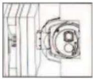 | Pre-configuration (Optional)Refer to (Optional) Configuration Programming in the Shipping Box, page 30. |
 | Mounting optionsRefer to Mounting Bracket Options, page 21. |
 | Camera connections (including power/communication)Refer to Connection, page 38. |
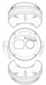 | Optional accessoriesRefer to (Optional) Installing a Sunshield, page 36. |
 | Camera settingsRefer to Configuration. |
5 Mounting
5.1 Mounting Location and Orientation Options
MIC cameras are designed for easy installation in various locations such as directly onto buildings and poles suitable to support CCTV equipment.
Select a secure installation location and mounting orientation for the device. Ideally, this is a location where the device cannot be interfered with either intentionally or accidentally.
Select a location where the MIC camera will not touch materials such as steel straps or cables. You can install the camera:
- onto a MIC-DCA or a MIC wall mount (MIC-WMB) with a MIC shallow conduit adapter (MIC-SCA). (Never install the wall mount only.)
or
– directly to a mounting surface using the supplied base gasket and the appropriate connector kit (sold separately):
- MIC-9K-IP67-5PK (IP67 Connector kit for MIC IP fusion 9000i, MIC IP ultra 7100i, and MIC IP starlight 7100i cameras)
To have an installation rated IP67, you must use the appropriate IP67 Connector Kit from Bosch.
Confirm that no residual water or moisture is in the bottom of camera. Ground the camera as described in the chapter "Installing a MIC Camera on a Hinged DCA."
The most common type of mounting location is the top of a pole suitable to support CCTV equipment and that provides a robust mounting platform to minimize camera motion and typically has a large base cabinet for mounting ancillary equipment such as power supplies.
Other locations for mounting the camera include the top of a building, the side (wall) of a building, the corner of a building, and under the eave of a building.
The camera can also be mounted on the side of a lamp post, pole, or similar column using the Pole Mount Bracket (MIC-PMB). Be aware that lamp posts can often be subject to movement and are not suitable platforms in all conditions or for all applications.

Notice!
Outdoor installation
For details about the proper configuration for installing your camera outdoors with surge and lightning protection, refer to the chapter "Installing the camera outdoors, page 27."
Ensure that the location has the appropriate clearance from power and lightning conductors, in accordance with NEC725 and NEC800 (CEC Rule 16-224 and CEC Section 60).
Do not install the device near:
- Any heat sources
- Any overhead power lines, power circuits, or electrical lights, or where the device may contact power lines, circuits, or lights
Isolate shielded CAT5e or CAT6 cable from any high voltage power lines in a separate grounded, metal conduit. Refer to the datasheet for test conditions for allowable transients / voltage fluctuations.

Notice!
Heat sources may obscure the thermal image
Heat sources in the direct FOV of the thermal camera or which can reflect from thermally reflective sources might obscure the thermal image.
Mounting surface recommendations for MIC mounting accessories
The mounting surface should be capable of supporting the combined weight of the MIC camera + MIC Illuminator + MIC mounting accessory (DCA, wall mount, corner bracket, etc.). All expected conditions of load, vibration and temperature should be considered when planning an installation. The material should accommodate a minimum pull-out strength of 275 kg (600 lb).
The mounting accessory should be secured to one of the following surfaces:
- Concrete (solid / cast)
- Concrete masonry unit (concrete block)
- Brick (all types)
- Metal (steel / aluminum, minimum 3 mm (0.125 in.) thick)
In all situations, Bosch recommends referencing any applicable building codes or professional structural engineering guidelines for a secure installation.
▶ Ensure that the selected mounting surface is capable of supporting the combined weight of the camera and mounting hardware (sold separately) under all expected conditions of load, vibration, wind, and temperature.

Caution!
Risk of lightning strikes
If the camera is installed in a highly exposed location where lightning strikes may occur, then Bosch recommends installing a separate lightning conductor within 0.5 m (1.6 ft) of the camera and at least 1.5 m (4.9 ft) higher than the camera. A good earth bonding connection to the camera housing itself will provide protection against damage from secondary strikes. The camera housing itself is constructed to cope with secondary strikes. If the correct lightning protection is applied, then no damage to the internal electronics or camera should result.
Installation in a damp environment (for example, near a coastline)
The fasteners shipped with the camera are designed to resist corrosion. Always use Bosch-supplied screws and other fasteners when installing the camera.
The camera head has factory-installed plastic screws that prevent corrosion in the screw holes when no MIC sunshield accessory is attached. Do not remove these screws until you install a sunshield accessory. For complete details, refer to the installation instructions for the sunshield accessory.
Before installation, inspect the metal parts of the camera for paint that is chipped or otherwise damaged. If you notice any paint damage, touch up the damage with paint or sealants available locally.
Avoid installation practices that may allow the camera's metal mountings to contact materials such as stainless steel. Such contact can result in galvanic corrosion and degrade the cosmetic appearance of the camera. These cosmetic damages caused by improper installation are not covered by warranty as they do not affect the functionality of the camera.
5.2 Mounting Options
See the figures that follow for illustrations of the correct and the incorrect mounting orientations of MIC cameras.
MIC cameras are designed to be mounted upright (straight up) or inverted (straight down).
See the figures below for illustrations of the correct and the incorrect mounting orientations of MIC cameras.

Correct mounting orientation. Canted and horizontal mounting orientations are not allowed!
The figures below illustrate the tilt range of the camera in upright orientation and in inverted orientation.
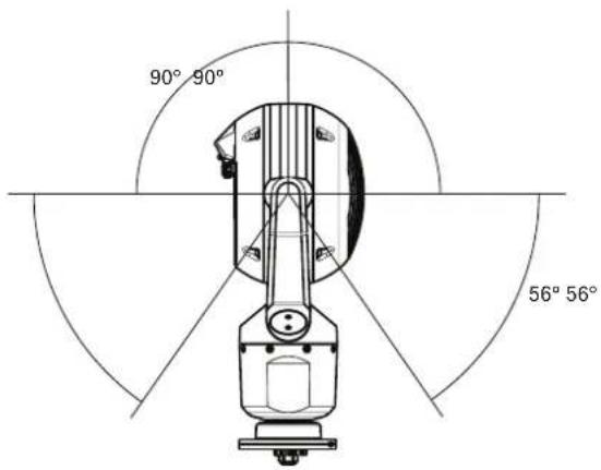

Tilt range of MIC IP fusion 9000i camera
5.3 Mounting Bracket Options
Bosch sells a complete series of mounting brackets that support multiple mounting configurations.
Always use only Bosch-supplied mounts, which are designed for safe installation of your MIC camera.
Refer to the MIC Series Mounting Brackets Installation Guide for complete installation instructions.
Mounting hardware recommendations for MIC mounting accessories
Fasteners are not supplied with the MIC mounting accessories for attachment to the mounting surface. The type of fastener necessary is dependent on the mounting surface.
Fasteners can include wedge anchors, sleeve anchors, single expansion anchors, double expansion anchors, machine screws, or 'Thru-Bolting' with a nut.
Fasteners are to be of a structural grade (ISO Class 10.9, SAE Grade 8) and zinc plated for moderate corrosion resistance. When installed in marine or similarly corrosive environments, stainless hardware (A2-800, A4-800) is recommended.
Fasteners are to be a minimum diameter of 8 mm (0.3125 in.).
All bolts must extend through the mounting surface and be secured with a flat washer, lock washer, and nut. All studs must be anchored to concrete or welded to a steel backing plate. In all situations, Bosch recommends referencing any applicable building codes or professional structural engineering guidelines for a secure installation.
The hinged DCA is well-suited to installations on top of a pole.

Figure 5.1: Typical Wall mount configuration
Note: Always install an SCA when you install a wall mount for any installation configuration. Route cables through the bottom of the SCA (to prevent water from running into the side or top of the SCA along the cables).
Through-wall Mount
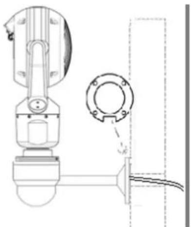
Typical direct wall mount (MIC9000 on WMB mounted directly to a wall (gasket required))
Down-wall Mount

Typical wall mount with SCA (MIC9000)
Pole Mount
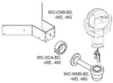
The figure below identifies the three mounting accessories (each sold separately) that are necessary to mount the MIC camera on the side of a pole.
Note: The figure identifies the part numbers, as well as the codes for the available colors (-BD for black, -WD for white, and -MG for grey) of each mounting accessory.

Figure 5.2: Typical Pole mount configuration

Typical pole mount configuration (MIC9000)

Figure 5.3: Typical Corner mount configuration
Note: Always install an SCA when you install a wall mount for any installation configuration. Route cables through the bottom of the SCA (to prevent water from running into the side or top of the SCA along the cables).
Typical corner mount configuration (MIC9000) Surface Mount
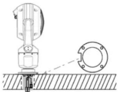
Direct surface mount (upright) with base gasket (MIC9000)

Direct surface mount (inverted) with base gasket + IP67 Weatherization/Connector Kit
5.4 Considerations for Mounting the Camera in Inverted Orientation
To change the camera orientation to "Inverted," complete the following steps:
- Remove the camera from the shipping box.
- Apply power to the camera.
- Access the web browser of the camera.
- Access the page Configuration.
- Navigate to Camera > Installer Menu > Orientation.
- Select "Inverted."
The camera head will rotate automatically into inverted position (180°).
Note the position of the visor when the camera is installed in inverted orientation. The visor will now be near the body of the camera.

Figure 5.4: MIC camera with camera head inverted
Note: It is not necessary to remove the section for the illuminator on the sunshield because the illuminator is attached to the opposite side of the camera visor.
Seal the mount so that moisture or water cannot collect and stay in the bottom of the MIC camera.
The figure that follows shows the camera installed in inverted orientation on a pole.

Figure 5.5: MIC camera mounted in inverted orientation (on pole)
6 Installing the camera outdoors
Cameras installed outdoors are typically exposed to surges, transients, and lightning. The details for wiring and installation are based on common practices for proper surge and lightning suppression.
The figure that follows is an illustration of the best practices for installing IP cameras outdoors with surge and lightning suppression.
Note that the illustration has an AUTODOME camera and a MIC camera and does not include representations of all models of IP cameras, including AUTODOME and MIC.
The illustration can represent any IP camera. Mounting hardware varies between units.
![graph TD A["Component 1"] --> B["Component 2"] B --> C["Component 3"] C --> D["Component 4"] D --> E["Component 5"] E --> F["Component 6"] F --> G["Component 7"] G --> H["Component 8"] H --> I["Component 9"] I --> J["Component 10"] J --> K["Component 11"] K --> L["Component 12"] L --> M["Component 1…](/content/2026/06/1407501/images/9effc2ad30bb92ab8c147c4b21e667f66c130f09d60a87e999313672b30c2cde.jpg)
Figure 6.1: Correct outdoor installation with proper surge/lightning suppression
| 1 | Indoor main building 2 Network switch with shielded ports and grounding as recommended by the manufacturer. All network cables must be terminated with shielded RJ45 connectors. | |
| 3 | Surge suppression for indoor equipment at cable entry | 4 Outdoor rated surge suppressor with shielded RJ45 connections that must be mounted as close to the camera as possible. Connect the ground per the manufacturer's installation manual. |
| 5 | Install Cat5e/Cat6 shielded Ethernet cable such as F/UTP shielded cable with twisted pairs (often referred to as FTP) or S/UTP braided shield with twisted pairs (often referred to as STP) with shielded RJ45 connectors.The cable must be routed through a permanently earthed metal conduit that is Earth-grounded across the entire span.The cables must be a maximum length of 100 m (328 ft). Power and signal cables must be in separate conduits with the correct physical separation distance between them. (Refer to the section Additional wiring guidelines.) | |
| 6 | Outdoor-rated midspan with shielded RJ45 connections. Ground the metal conduit to the midspan per the installation instructions of the camera/midspan. | 7 Equipment enclosure with AC power source for the midspan |
| 8 | Optional outdoor-rated network switch or patch panel | 9 Connect the Bus Bar to the Equipment Grounding Electrode. All equipment must be bonded to this common bus bar. |
| 10 | Lightning Rod (Refer to the section Lightning rod, down conductor, and electrode.) | 11 Down Conductor (Refer to the section Lightning rod, down conductor, and electrode.) |
| 12 | Lightning Rod Grounding Electrode (Refer to the sections Lightning rod, down conductor, and electrode and Separate grounding electrodes.) | 13 Equipment Grounding Electrode (Refer to the section Separate grounding electrodes.) |
Additional wiring guidelines
Maintain the physical separation distance between the Cat5e/Cat6 shielded Ethernet cable and high voltage/EMF sources. These are typical recommendations, but also refer to local electrical codes.
| Voltage range Minimum separation distance | |
| For <600 VAC 50 mm (2 in.) | |
| For >600 VAC and <3 kV 1.5 m (5 ft) | |
| For >3 kV 3 m (10 ft) |
Use shielded cables for alarms, audio, or any other connections when applicable.
Lightning rod, down conductor, and electrode
- Note that the lightning rod down conductor connects directly to the grounding electrode. – Refer to NFPA 780, Class 1 & 2, UL96A, and to the equivalent code appropriate for the country/region.
- Follow the installation instructions of the lightning rod manufacturer.
Separate grounding electrodes
Some standards call for a common electrode for the equipment bus bar and the lightning rod. Refer to NFPA 780, Class 1 & 2, UL96A, and to the equivalent code appropriate for the country/region.
Metal pole grounding
If a metal pole is used, refer to NFPA 780, Class 1 & 2, UL96A, and to the equivalent code appropriate for the country/region.
Camera Housings and Mounts
- Use only Bosch mounts listed on the datasheet of the specific camera.
- Follow all grounding for the camera housings and mounts per the installation manual.
7 (Optional) Configuration Programming in the Shipping Box
The camera packaging allows installers to connect the camera to the network and configure the camera still in the box.

Caution!
Risk of damage to camera
Do not change the camera orientation to "Inverted" while the camera is still in the box. The camera head must be free to rotate. If you must change the camera's orientation to
"Inverted," remove the camera from the box and configure it by following the steps in
(Optional) Configuration Programming on a Temporary Table-top Stand.
- Remove the packing material to access the camera's electrical connectors.

- Supply power to the camera and connect the camera to the network, page 40. Note that the wiper moves one to three times across the camera window, and then returns to parked position.
- Configure the camera. Refer to the separate User Manual for details.
- Disconnect the wires/cables from the connectors in the base of the camera.
Refer to
- (Optional) Configuration Programming on a Temporary Table-top Stand, page 31
8 (Optional) Configuration Programming on a Temporary Table-top Stand

Caution!
Take extra care lifting or moving MIC cameras because of their weight.
The camera (still in the foam) can stand temporarily on a flat, horizontal surface such as a desk or a table during initial network connection and configuration.
- Remove the packing material to access the camera's electrical connectors.
- Remove the foam covering the head of the camera.
- Remove the camera, still in the foam, from the box. Place the camera upright on a flat, horizontal surface.
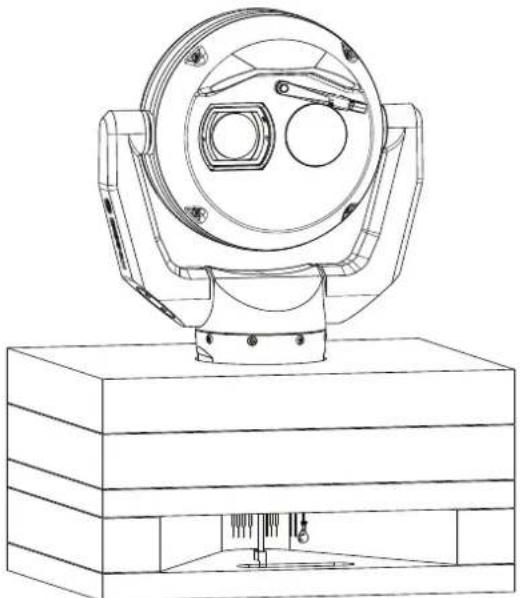
- Supply power to the camera and connect the camera to the network, page 40. Note that the wiper moves one to three times across the camera window, and then returns to parked position.
- Configure the camera. Refer to the separate User Manual for details.

Notice!
If you change the camera orientation to "Inverted" (from the page Configuration of the web browser: Camera > Installer Menu > Orientation), then the camera head will rotate automatically into inverted position (180°). Note that the visor will now be near the body of the camera.
- Disconnect the wires/cables from the connectors in the base of the camera.
9 Installing a MIC Camera on a Hinged DCA
The hinge feature allows installers to "hang" the camera temporarily but securely during installation for easier connection of cables/wiring before final bolts are installed.
Parts List
| Quantity Component | |
| 1 MIC Hinged DCA (MIC-DCA-Hx) | |
| 4 Stainless steel hex bolts, M8 x 30 | |
| 4 Stainless steel plain washers, M8 | |
| 1 O-ring, 80 mm x 3 mm | |
| 1 conduit adapter (male M25 to female 3/4" NPT) (Available in specific regions only.) | |
| 1 Blanking plug, M25 x 1.5, with O-ring | |
| 1 Quick Installation Guide |
Additional Tools Required

Warning!
Ensure not to damage the paint on the housing of the camera or the mount.
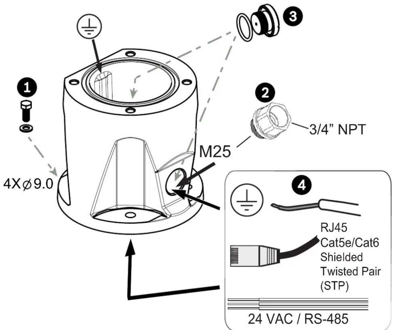
- Attach the DCA to the mounting location using user-supplied hardware (item 1). (Bosch recommends stainless steel bolts and washers.)
- Attach user-supplied conduit or glands to the side hole or to the bottom hole. If applicable, use the conduit adapter (male M25 to female 3/4 in. NPT) (item 2, included with the DCA).
- Route cables into the DCA (item 4), either through the bottom or from the side.
- Use the blanking plug and O-ring (item 3, included with the DCA) to close the unused hole (bottom or side) in the DCA.
- Insert the O-ring (item 1).
- Loosen the Torx bolts two (2) turns (items 2). Slide the hook up (item 3). Tighten the bolts to hold the hook in place temporarily (item 4).
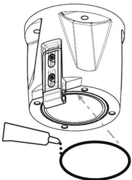
- For inverted installation, apply a small amount of grease to the primary O-ring to hold it in place.
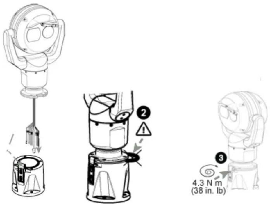
- Push the wires from the camera base into the DCA while positioning the base pin of the camera under the DCA hook (item 1). Avoid pinching the wires! (item 2). Loosen the hook bolts, and then slide the hook down to secure the camera pin. Fully tighten the hook bolts (item 3).

- Carefully tilt the camera to the side with the pin under the hook.

Notice!
Risk of damage to the camera!
Ease the camera into position; do not allow it to fall unassisted into rotated position or allow head to slam into any surface or object!
- Make the appropriate electrical connections. Refer to the chapter Connections for more information.
- Screw the green GND wire from the camera base to the ground hole on the inside wall of the DCA. If the DCA is not mounted to earth grounded surface, attach user-supplied grounded wire (item 4 in step 1) to the same connection point.

- Carefully tip the camera to its final position. Avoid pinching wires between the camera base and the DCA! Insert four washers and hex bolts (supplied).
10 (Optional) Installing a Sunshield
| Quantity Component | |
| 2 Sunshield shells | |
| 2 Spike strips | |
| 4 Screws | |
| 4 Flat washers | |
| 1 Quick Installation Guide |
Additional Tools Required
| 1 Phillips- | head screwdriver, #2, to remove factory-installed plastic screws from the camera head |
| 1 Torx driver, T20, for M4 Torx head screws | |
![graph LR A["24VAC"] --> B["Cloud"] B <--> C["Laptop"]](/content/2026/06/1407501/images/d600b1c3815710eb24dd0cb4398d260df19929e92aade35e661a662e07064cd7.jpg)
- Mount the camera. Apply power (24 VAC or 95W High PoE). Connect using a web browser or VMS.
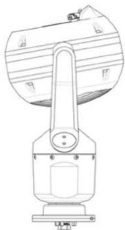
- Operate the tilt to near the upper limit.
- Remove and discard 4 screws.

- Align the sunshield shells so that the pins slide into the bolt heads on the faceplate.
- Ensure that the sunshield mounting holes align with the holes in the rear of the camera head. Install 4 screws and washers.
- Ensure that the gap between the two sunshield halves is approximately 3.5 mm (1/8 in.).
- If the rear gap is not parallel, rework to ensure that the pins are seated properly in the bolt heads on the faceplate.
- If you will install an illuminator on a unit mounted in upright orientation:
Cut out the inset area in the sunshield shell with a pair of diagonal cutters. The inset area provides space to attach the illuminator. Discard the cut-out plastic.
Note: This step does not apply to cameras mounted in inverted orientation.
- Note that when you install the sunshield correctly, the sunshield appears as in the following figure.
11 Connection
11.1 About Camera Power and Control
The camera incorporates a network video server that encodes video images and PTZ control commands for transmission over a TCP/IP or UDP/IP network.
With its H.264 or H.265 encoding, it is ideally suited for IP communication and for remote access to digital video recorders and multiplexers. Use existing networks to achieve quick and easy integration with CCTV systems or local networks. Several receivers can receive video images simultaneously from a single camera.
11.2 Power Source Options
The camera can be powered by a network compliant to High Power-over-Ethernet using a Bosch model of High PoE Midspan (sold separately). With this configuration, only a single cable connection
(Cat5e/Cat6 Shielded Twisted Pair (STP)) is needed to view, to power, and to control the camera.
For maximum reliability, the camera can be connected simultaneously to a High PoE Midspan and a separate 24 VAC power source. If High PoE and 24 VAC are applied simultaneously, the camera usually selects the High PoE Midspan and will draw minimal power from the auxiliary input (24 VAC). If the High PoE Midspan power source fails, the camera switches power input seamlessly to 24 VAC. After the High PoE Midspan power source is restored, the camera switches power input again to the High PoE Midspan.
The power supply must be certified to UL/IEC 60950-1 2nd Edition, AM1+AM2 or UL/IEC 62368-1 2nd Ed, Output 24 VAC, LPS, +65 °C (+149 °F) min.
Bosch recommends only a midspan power source for models with an attached illuminator. The table below identifies the power devices that can be connected simultaneously to the camera.
| If power is supplied from: Camera | can receive power simultaneously from: |
| 95 W midspan (NPD-9501A) 24 VAC PSU: VG4-A-PSU1 or VG4-A-PSU2 | |

Notice!
Connect the 24 VAC connections from the MIC camera to the heater output of the power supply (VG4-A-PSU1 or VG4-A-PSU2).

Caution!
Compliance with EN50130-4 Alarm Standard – CCTV for Security Applications To meet the requirements of the EN50130-4 Alarm Standard, an ancillary uninterruptable power (UPS) supply is necessary. The UPS must have a Transfer Time between 2–6 ms and a Backup Runtime of greater than 5 seconds for the power level as specified on the product datasheet.
Maximum wire distances from 24 VAC power supply to MIC IP fusion 9000i camera
| VA / Watts 1 | 4 AWG(2.5 mm) | 16 AWG(1.5 mm) | 18 AWG(1.0 mm) |
| 90 / 65 39 | m (127 ft) 24 m | (80 ft) 15 m | (50 ft) |
11.3 Ethernet Connections

Caution!
Cat5e/Cat6 shielded Ethernet cables must be routed through earth-grounded, liquid-tight conduit capable of withstanding the outdoor environment.
| Cable Type Cat5e/Cat6 | Shielded Twisted Pair (STP) Ethernet (directly to the camera, or to a network switch between the camera and the network)Note: Cat5e/Cat6 Shielded Twisted Pair (STP) cable is required in order to meet European regulatory EMC standards. |
| Maximum Distance 100 m (330 ft) | |
| Ethernet 10BASE-T/100 | BASE-TX, auto-sensing, half/full duplex |
| Terminal Connector RJ45, Male | |
| High PoE (95 W) Use a | midspan sold by Bosch, or a midspan that is offered as a compatible alternative. |
Note: Consult the National Electrical Code (NEC) or other regional standards for cable bundling requirements and limitations.
11.4 Camera Connections
All electrical and data connections from the camera are made from the connectors in the base of the camera.

| Description Wire Color | ||
| 1 Chassis (Earth) ground wire (18 gage) with connector lug Green | ||
| 2 24 VAC power wires (24 gage) to Pins 4 and 5 of connector labeled P107 in VG4-A-PSU1 or VG4-A-PSU2 (if not using a High PoE network)* | Line (L) = BlackNeutral (N) = White | |
| 3 RS-485 connections for communication to / from the MIC-ALM-WAS-24 or other device providing legacy serial protocol signals * | + = Purple- = YellowGND = Brown | |
| 4 RJ45 (Cat5e/Cat6) connector (male) (supporting High PoE) for power and communication between a Bosch High PoE Midspan | ||
| 5 Audio wires (twisted pair cable recommended) Audio IN + = Red | Audio IN - = Light blueAudio OUT + = OrangeAudio OUT - = Dark blue | |
| 6 Wire connectors on 9 wires (numbers 2, 3, and 5 in the corresponding graphic)Note: The quick clips should remain on unused wires. If the clips are removed, cover the exposed copper on the wires with electrical tape to prevent the unused wires from electrically shorting to one another or to the mount enclosure. | ||
| 7 RJ45 coupler (female to female) | ||
For more information, refer to the installation manual Power Supply Units for AUTODOME 7000i, AUTODOME 7100i, and MIC cameras (shipped with VG4-A-PSU1 and VG4-A-PSU2). Note: If the MIC camera will be installed directly to a mounting surface, instead of onto a MIC DCA or a MIC wall mount bracket, Bosch recommends using the connector kit for your model of camera to protect the connections against moisture and dust particles. Each kit provides components for connecting as many as 5 MIC cameras. - MIC-9K-IP67-5PK (Connector kit for MIC IP fusion 9000i). Not using the IP67 Connector Kit will void the camera warranty. Note: The PoE connection is not intended to be connected to exposed (outside plant) networks. Seal the base of the camera against moisture ingress (standing water).
11.5 Connect the Camera to the Network
- Make the appropriate network connections depending on the power source of your IP network:
- If using a High PoE midspan power source:
a. Connect one end of a Cat5e/Cat6 Shielded Twisted Pair (STP) Ethernet cable to the RJ45 connector of the camera. b. Connect the other end of the cable to the DATA + POWER OUT port on the midspan.
Note: You must ground cable at both ends!
c. Connect a Cat5e/Cat6 Shielded Twisted Pair (STP) Ethernet cable from the DATA port of the midspan device to the Local Area Network (LAN).
- If not using High PoE: Connect a Cat5e/Cat6 Shielded Twisted Pair (STP) Ethernet cable from the RJ45 connector of the camera to the Local Area Network (LAN).
- If not using PoE and if connecting directly to a computer, DVR/NVR, or other related network device: Connect either a Cat5e/Cat6 Shielded Twisted Pair (STP) Ethernet cable or a crossover Ethernet cable between the RJ45 connector of the camera and the network device. Note: You must ground cable at both ends!
- If applicable, connect the 24 VAC wires to the power source.
- If applicable, connect the RS-485 wires to the MIC-ALM-WAS-24 (optional).
- Attach the ground wire from the camera to an earth-ground connection on the mounting surface using the supplied screw or a suitable user-supplied fastener.
- If applicable, connect the AUDIO IN and AUDIO OUT wires to the appropriate line level audio device.
12 Typical System Configurations
![graph TD A["OMVMS, BSC, 3rd party VMS; Web Browser, etc"] --> B["Network Switch"] C["VRM"] --> D["NAS Disk Array"] D --> E["Analog monitor"] E --> F["Decoder"] F --> G["Controller"] G --> H["Analog monitor"] H --> I["Decoder"] I --> J["Analog matrix"] J --> K["Internet"] K --> L["Firewall"] M["Remot…](/content/2026/06/1407501/images/50634373ccf4fe3105162595837b6dc06b0c947e5f1651ec269eb727115f2828.jpg)
MIC IP fusion 9000i System Configuration Options
13 Troubleshooting
Table of Troubleshooting Issues
The table below identifies issues that could occur with the camera, and how to resolve them. Note: Refer to the Error Codes section of the manual for descriptions of the error codes that appear on the OSD. The section also lists recommended actions to resolve the error codes.
| Problem Questions to Ask/Actions to | Resolve the Problem |
| No camera control. - Ensure that the | LAN cable has good connection and is secured.- Refresh the browser and ensure that video is updated.- Cycle the camera's power off and on.- Reboot the computer.- Refer to Status Code 17 in Error Codes. |
| Camera moves when attempting to move other cameras. | - Check that the camera's IP address is properly set.If the camera's IP address is not set, then:- Use Configuration Manager to confirm that two cameras do not have the same IP address. If they do, change the address of one of the cameras. |
| No Network Connection. - Check all n | network connections.- Ensure that the maximum distance between any two Ethernet connections is 100 m (328 ft) or less.If OK, then if you are behind a firewall, ensure that the Video Transmission mode is set to UDP. |
| Camera does not operate at all, or does not operate as expected, after being subjected to extreme low temperatures (below -40 °C (-40 °F)). | - Allow the camera to warm up. The camera requires a 60-minute warm-up prior to PTZ operations.- If camera does not operate after this warm-up period, then reset the camera. In the URL line of your web browser, type "/reset" at the end of the IP address of the camera.- Refer to Status Code 7 in Error Codes. |
| The contrast on the screen is too weak. | - Adjust the contrast feature of the monitor. Is the camera exposed to strong light? If so, change the camera position.- Adjust the Optical or thermal camera picture settings for your scene as described in Picture Settings or Picture Settings Thermal in the User Manual. |
| No video. - Check that the mains pow | er to the power supply is on.- If providing power via 24VAC, ensure that the 24VAC voltage at the camera is between 21VAC and 30VAC.- If providing power via High PoE, ensure that the lights on the midspan indicate correct operation. If they do not, see the midspan manual for further details.- Check to see if you can access a web page.- If you can, then cycle the camera's power off and on and check that the optical camera iris isn't closed. If this doesn't correct the problem, switch the Stream from Stream 1 or Stream 2 to M-JPEG. If this corrects the problem, re-install the latest Video SDK.- If you cannot, then you may have the wrong IP address. Use Configuration Manager to identify the correct IP address.If OK, then check that there is 24 V output from the transformer.If OK, then check the integrity of all wires and mating connectors to the camera. |
| Picture is dark (optical image). - Check that the Gain Control is set to High.If OK, then- Check that the Auto Iris Level is set to the appropriate level. | |
| Background is too bright to see subject (optical image). | Turn on backlight compensation. |
| Camera reboots frequently or intermittently | Your camera has an improper network connection. Test your camera with another power supply.Check the Bosch website for a software update that might address the issue. |
| No OSD messages appear. Bosch's Vide | deo SDK is required. Video management software from third parties does not use the SDK. |
Additional troubleshooting for MIC thermal imagers.
| Problem Explanation Solution | ||
| A small square appears intermittently at the upper right of the video output. | This symbol warns that flat-field correction (FFC) is about to begin. | Do nothing; this is normal operation for the thermal camera. |
| The thermal image appears 'grainy'. | This often occurs when the temperature of the camera fluctuates, such as after the camera is powered on, or when ambient temperature is changing. | Wait for the camera to perform a flat-field correction (FFC). |
| The thermal image is of poor quality. | Thermal image settings are not optimized for the type of scene being viewed. | Adjust the thermal camera settings to optimize the quality of the image. Refer to section on Thermal Camera Settings in Operation Manual. |
| The picture shows images that aren’t present in the scene. | Check to see if there the heat of objects are being reflected off a surface causing thermal reflections. |
14 Maintenance
Regular maintenance of your MIC camera will preserve the MIC, especially the surface finish, for an extended period.
Cleaning – Remove power from the device before cleaning. Generally, using a dry cloth for cleaning is sufficient, but a moist, fluff-free cloth may also be used. Do not use liquid cleaners or aerosol cleaners.
In corrosive environments, you should clean the camera surface periodically with fresh water.
▶ Wash the camera thoroughly with fresh water: - Regularly (1-2 times per quarter, or more frequently if possible) - Immediately after an event such as a sea storm that could introduce a layer of salt on the camera's surface
Use a flow rate of 150-145 liter/minute. Hold the nozzle a minimum distance of 1 m from the camera.
In certain use cases, it might help to use a solution of hydrophobic liquid to prevent long-term buildup of salt layers on the camera's surface.
Note: Do not use water pressure greater than 96.5 kPa (14 psi) to wash the unit.
No User-serviceable Parts
Except for the external wiper blade, the device contains no user-serviceable parts. Contact your local Bosch service center for device maintenance and repair. In the event of failure, the device should be removed from site for repair.
On-Site Inspection
It is recommended that the device be inspected on-site every six months to check mounting bolts for tightness, security, and any signs of physical damage. Inspection of this device shall only be carried out by suitably-trained personnel in accordance with the applicable code of practice (for example, EN 60097-17).
The following sticker appears on each side of the MIC camera head, just above the tilt arms, to warn that the surface may be hot:

14.1 Replacing a wiper assembly
- Put a piece of thin, protective material between the window glass and the wiper to prevent accidental damage.

- With one hand, hold the wiper arm firmly in place to restrict rotational movement.
- With the other hand, using a 7mm Hex socket or nut driver, rotate the acorn nut counterclockwise until the nut is free from the wiper shaft.

- Remove the wiper spring, hub, arm, and blade assembly from the wiper shaft.

- Connect the new wiper arm and the new wiper hub.

- Insert the new blade assembly into the new wiper arm.

- Slide the new wiper hub and the attached parts onto the wiper shaft.

- Slide the new wiper spring onto the wiper shaft and over the new wiper arm.

- Apply Loctite 243 to the hole of the acorn nut.
- Lightly thread the new acorn nut onto the wiper shaft over the new wiper spring and new wiper hub.
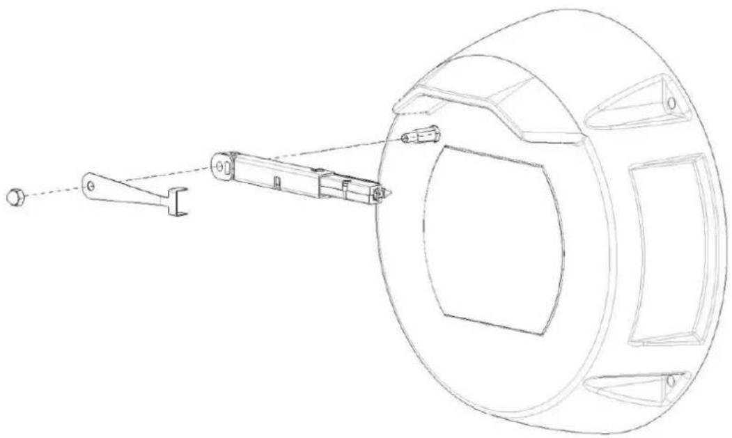
- With one hand, hold the new wiper arm firmly in place to restrict rotational movement and to keep the wiper assembly parallel with the flat top of the glass.
- With the other hand, using a 7mm Hex socket or nut driver, tighten the new acorn nut clockwise to a torque value of 1.0 Nm.

15 Decommissioning
15.1 Transfer
The device should only be passed on together with this Installation manual.
15.2 Disposal

Disposal - Your Bosch product was developed and manufactured with high-quality material and components that can be recycled and reused. This symbol means that electronic and electrical appliances, which have reached the end of their working life, must be collected and disposed of separately from household waste material. Separate collecting systems are usually in place for disused electronic and electrical products. Please dispose of these units at an environmentally compatible recycling facility, per European Directive 2012/19/EU.
16 Technical data
For product specifications, see the datasheet for your camera, available on the appropriate product pages of the Online Product Catalog at www.boschsecurity.com.
17 Support services and Bosch Academy

Support
Access our support services at www.boschsecurity.com/xc/en/support/.

Bosch Building Technologies Academy
Visit the Bosch Building Technologies Academy website and have access to training courses, video tutorials and documents: www.boschsecurity.com/xc/en/support/training/
Bosch Security Systems B.V.
Torenallee 49
5617 BA Eindhoven
Netherlands
www.boschsecurity.com
© Bosch Security Systems B.V., 2023
Building solutions for a better life.
- TABLE OF CONTENTS
- SAFETY
- INTRODUCTION
- ABOUT THIS MANUAL
- LEGAL INFORMATION
- COPYRIGHT
- TRADEMARKS
- SAFETY PRECAUTIONS
- DANGER
- WARNING
- CAUTION
- NOTICE
- IMPORTANT NOTICES
- GROUNDING
- FCC INFORMATION
- FCC SUPPLIERS DECLARATION OF CONFORMITY
- RESPONSIBLE PARTY
- UL DISCLAIMER
- USE LATEST SOFTWARE
- CUSTOMER SUPPORT AND SERVICE
- USA AND CANADA
- CUSTOMER SERVICE
- TECHNICAL SUPPORT
- EUROPE, MIDDLE EAST, AFRICA, AND ASIA PACIFIC REGIONS
- MORE INFORMATION
- ADDITIONAL PRODUCTS REQUIRED
- ADDITIONAL TOOLS
- ESTABLISHING THE CONNECTION
- NOTE
- PASSWORD PROTECTION IN CAMERA
- PRODUCT DESCRIPTION
- INSTALLATION OVERVIEW
- MOUNTING
- MOUNTING LOCATION AND ORIENTATION OPTIONS
- MOUNTING SURFACE RECOMMENDATIONS FOR MIC MOUNTING ACCESSORIES
- INSTALLATION IN A DAMP ENVIRONMENT (FOR EXAMPLE, NEAR A COASTLINE)
- MOUNTING OPTIONS
- MOUNTING BRACKET OPTIONS
- MOUNTING HARDWARE RECOMMENDATIONS FOR MIC MOUNTING ACCESSORIES
- THROUGH-WALL MOUNT
- DOWN-WALL MOUNT
- POLE MOUNT
- CONSIDERATIONS FOR MOUNTING THE CAMERA IN INVERTED ORIENTATION
- INSTALLING THE CAMERA OUTDOORS
- ADDITIONAL WIRING GUIDELINES
- LIGHTNING ROD, DOWN CONDUCTOR, AND ELECTRODE
- SEPARATE GROUNDING ELECTRODES
- METAL POLE GROUNDING
- CAMERA HOUSINGS AND MOUNTS
- (OPTIONAL) CONFIGURATION PROGRAMMING IN THE SHIPPING BOX
- REFER TO
- (OPTIONAL) CONFIGURATION PROGRAMMING ON A TEMPORARY TABLE-TOP STAND
- INSTALLING A MIC CAMERA ON A HINGED DCA
- ADDITIONAL TOOLS REQUIRED
- (OPTIONAL) INSTALLING A SUNSHIELD
- CONNECTION
- ABOUT CAMERA POWER AND CONTROL
- POWER SOURCE OPTIONS
- ETHERNET CONNECTIONS
- CAMERA CONNECTIONS
- CONNECT THE CAMERA TO THE NETWORK
- TYPICAL SYSTEM CONFIGURATIONS
- TROUBLESHOOTING
- TABLE OF TROUBLESHOOTING ISSUES
- MAINTENANCE
- NO USER-SERVICEABLE PARTS
- ON-SITE INSPECTION
- REPLACING A WIPER ASSEMBLY
- DECOMMISSIONING
- TRANSFER
- DISPOSAL
- TECHNICAL DATA
- SUPPORT SERVICES AND BOSCH ACADEMY
- SUPPORT
- BOSCH BUILDING TECHNOLOGIES ACADEMY
Brand : BOSCH
Model : MIC IP FUSION 9000i
Category : Surveillance Camera