
PNG655RE - Monitor SHARP - Free user manual and instructions
Find the device manual for free PNG655RE SHARP in PDF.
| Product Type | Professional LCD Monitor |
| Brand | Sharp |
| Model | PNG655RE |
| Screen Size | 65 inches (163.9 cm diagonal) |
| Panel Type | Low-reflection LCD TFT ASV |
| Maximum Resolution | 1080 x 1920 pixels |
| Displayable Colors | 16.77 million (8 bits/color) |
| Viewing Angle | 176° (horizontal/vertical, contrast ratio ≥10) |
| Dimensions (W x D x H) | 923 x 150 x 1572 mm (without protrusions) |
| Weight | Approx. 66 kg (without temporary support) |
| Power Supply | AC 100-240 V, 50/60 Hz |
| Power Consumption | 560 W (standby: 4.0 W, no signal mode: 10 W) |
| Operating Temperature | 0°C to 40°C |
| Operating Humidity | 20% to 80% (without condensation) |
| Video Inputs | DVI-D (x2), Mini D-sub 15-pin, BNC (component/composite), audio (mini-jack, RCA) |
| Video Outputs | DVI-D (loop), audio RCA, RS-232C |
| Built-in Speakers | 2 x 7 W (impedance 6 Ω) |
| Main Functions | Multi-screen enlargement (up to 5x5), PIP/PbyP, on/off timer, setting lock |
| Cleaning | Disconnect, use a dry cloth; no liquids or aerosols |
| Safety | Do not open; use supplied cord; install near an accessible outlet |
| Spare Parts and Repairability | Use parts specified by manufacturer; repair by qualified personnel |
| Supplied Accessories | Power cord, remote control, R-6 batteries (x2), CD-ROM, user manual |
| General Information | Class A (may cause interference in residential environments); contains mercury (fluorescent lamp) |
Frequently Asked Questions - PNG655RE SHARP
User questions about PNG655RE SHARP
0 question about this device. Answer the ones you know or ask your own.
Ask a new question about this device
Download the instructions for your Monitor in PDF format for free! Find your manual PNG655RE - SHARP and take your electronic device back in hand. On this page are published all the documents necessary for the use of your device. PNG655RE by SHARP.
USER MANUAL PNG655RE SHARP
Authorised representative responsible for the European Union Community Market
The wires in this mains lead are coloured in accordance with the following code:
GREEN-AND-YELLOW :
Earth
BLUE :
Neutral
BROWN :
Live
As the colours of the wires in the mains lead of this apparatus may not correspond with the coloured markings identifying the terminals in your plug proceed as follows:
- The wire which is coloured GREEN-AND-YELLOW must be connected to the terminal in the plug which is marked by the letter E or by the safety earth 12 or coloured green or green-and-yellow.
- The wire which is coloured BLUE must be connected to the terminal which is marked with the letter N or coloured black.
- The wire which is coloured BROWN must be connected to the terminal which is marked with the letter L or coloured red.
Ensure that your equipment is connected correctly. If you are in any doubt consult a qualified electrician.
"WARNING: THIS APPARATUS MUST BE EARTHED."
WARNING: TO REDUCE THE RISK OF FIRE OR ELECTRIC SHOCK, DO NOT EXPOSE THIS PRODUCT TO RAIN OR MOISTURE.

CAUTION
RISK OF ELECTRIC SHOCK DO NOT OPEN

CAUTION: TO REDUCE THE RISK OF ELECTRIC SHOCK, DO NOT REMOVE COVER. NO USER-SERVICEABLE PARTS INSIDE. REFER SERVICING TO QUALIFIED SERVICE PERSONNEL.

The lightning flash with arrowhead symbol, within an equilateral triangle, is intended to alert the user to the presence of uninsulated “dangerous voltage” within the product’s enclosure that may be of sufficient magnitude to constitute a risk of electric shock to persons.

The exclamation point within a triangle is intended to alert the user to the presence of important operating and maintenance (servicing) instructions in the literature accompanying the product.
CAUTION: The AC outlet shall be installed near the equipment and shall be easily accessible.
CAUTION: Use the supplied power cord as it is.
This product utilises fluorescent tubes containing a small amount of mercury.
Disposal of these materials may be regulated due to environmental considerations. For disposal or recycling information, please contact your local authorities.

Attention: Your product is marked with this symbol. It means that used electrical and electronic products should not be mixed with general household waste. There is a separate collection system for these products.
A. Information on Disposal for Users (private households)
1. In the European Union
Attention: If you want to dispose of this equipment, please do not use the ordinary dustbin!
Used electrical and electronic equipment must be treated separately and in accordance with legislation that requires proper treatment, recovery and recycling of used electrical and electronic equipment.
Following the implementation by member states, private households within the EU states may return their used electrical and electronic equipment to designated collection facilities free of charge*. In some countries* your local retailer may also take back your old product free of charge if you purchase a similar new one.
*) Please contact your local authority for further details.
If your used electrical or electronic equipment has batteries or accumulators, please dispose of these separately beforehand according to local requirements.
By disposing of this product correctly you will help ensure that the waste undergoes the necessary treatment, recovery and recycling and thus prevent potential negative effects on the environment and human health which could otherwise arise due to inappropriate waste handling.
2. In other Countries outside the EU
If you wish to discard this product, please contact your local authorities and ask for the correct method of disposal.
For Switzerland: Used electrical or electronic equipment can be returned free of charge to the dealer, even if you don't purchase a new product. Further collection facilities are listed on the homepage of www.swico.ch or www.sens.ch.
B. Information on Disposal for Business Users
1. In the European Union
If the product is used for business purposes and you want to discard it:
Please contact your SHARP dealer who will inform you about the take-back of the product. You might be charged for the costs arising from take-back and recycling. Small products (and small amounts) might be taken back by your local collection facilities.
For Spain: Please contact the established collection system or your local authority for take-back of your used products.
2. In other Countries outside the EU
If you wish to discard of this product, please contact your local authorities and ask for the correct method of disposal.
Thank you for your purchase of a SHARP LCD product. To ensure safety and many years of trouble-free operation of your product, please read the Safety Precautions carefully before using this product.
SAFETY PRECAUTIONS
Electricity is used to perform many useful functions, but it can also cause personal injuries and property damage if improperly handled. This product has been engineered and manufactured with the highest priority on safety. However, improper use can result in electric shock and/or fire. In order to prevent potential danger, please observe the following instructions when installing, operating and cleaning the product. To ensure your safety and prolong the service life of your LCD product, please read the following precautions carefully before using the product.
- Read instructions — All operating instructions must be read and understood before the product is operated.
- Keep this manual in a safe place — These safety and operating instructions must be kept in a safe place for future reference.
- Observe warnings — All warnings on the product and in the instructions must be observed closely.
- Follow instructions — All operating instructions must be followed.
- Cleaning — Unplug the power cord from the AC outlet before cleaning the product. Use a dry cloth to clean the product. Do not use liquid cleaners or aerosol cleaners.
- Attachments — Do not use attachments not recommended by the manufacturer. Use of inadequate attachments can result in accidents.
- Water and moisture — Do not use the product near water.
- Ventilation — The vents and other openings in the cabinet are designed for ventilation.
Do not cover or block these vents and openings since insufficient ventilation can cause overheating and/or shorten the life of the product. Do not place the product on a sofa, rug or other similar surface, since they can block ventilation openings.
Do not place the product in an enclosed place such as a bookcase or rack, unless proper ventilation is provided or the manufacturer's instructions are followed. - Power cord protection — The power cords must be routed properly to prevent people from stepping on them or objects from resting on them.
- The LCD panel used in this product is made of glass. Therefore, it can break when the product is dropped or applied with impact. Be careful not to be injured by broken glass pieces in case the LCD panel breaks.
- Overloading — Do not overload AC outlets or extension cords. Overloading can cause fire or electric shock.
- Entering of objects and liquids — Never insert an object into the product through vents or openings. High voltage flows in the product, and inserting an object can cause electric shock and/or short internal parts.
For the same reason, do not spill water or liquid on the product. - Servicing — Do not attempt to service the product yourself. Removing covers can expose you to high voltage and other dangerous conditions. Request a qualified service person to perform servicing.
-
Repair — If any of the following conditions occurs, unplug the power cord from the AC outlet, and request a qualified service person to perform repairs.
a. When the power cord or plug is damaged.
b. When a liquid was spilled on the product or when objects have fallen into the product.
c. When the product has been exposed to rain or water.
d. When the product does not operate properly as described in the operating instructions.
Do not touch the controls other than those described in the operating instructions. Improper adjustment of controls not described in the instructions can cause damage, which often requires extensive adjustment work by a qualified technician.
e. When the product has been dropped or damaged.
f. When the product displays an abnormal condition. Any noticeable abnormality in the product indicates that the product needs servicing. -
Replacement parts — In case the product needs replacement parts, make sure that the service person uses replacement parts specified by the manufacturer, or those with the same characteristics and performance as the original parts. Use of unauthorised parts can result in fire, electric shock and/or other danger.
- Safety checks — Upon completion of service or repair work, request the service technician to perform safety checks to ensure that the product is in proper operating condition.
- Wall mounting — When mounting the product on a wall, be sure to install the product according to the method recommended by the manufacturer.
- Heat sources — Keep the product away from heat sources such as radiators, heaters, stoves and other heat-generating products (including amplifiers).
- Usage of the monitor must not be accompanied by fatal risks or dangers that, could lead directly to death, personal injury, severe physical damage or other loss, including nuclear reaction control in nuclear facility, medical life support system, and missile launch control in a weapon system.
WARNING:
This is a class A product. In a domestic environment this product may cause radio interference in which case the user may be required to take adequate counter measures.
WARNING:
Do not use the factory-installed temporary stand when installing the LCD monitor.
This stand is for temporary use only until the monitor is properly mounted.
The temporary stand does not support the LCD monitor securely. Using the temporary stand may cause injury.
- The TFT colour LCD panel used in this monitor is made with the application of high precision technology. However, there may be minute points on the screen where pixels never light or are permanently lit. Also, if the screen is viewed from an acute angle there may be uneven colours or brightness. Please note that these are not malfunctions but common phenomena of LCDs and will not affect the performance of the monitor.
- Do not display a still picture for a long period, as this could cause a residual image.
- Never rub or tap the monitor with hard objects.
- Please understand that Sharp Corporation bears no responsibility for errors made during use by the customer or a third party, nor for any other malfunctions or damage to this product arising during use, except where indemnity liability is recognised under law.
- This monitor and its accessories may be upgraded without advance notice.
- Do not use the monitor where there is a lot of dust, where humidity is high, or where the monitor may come into contact with oil or steam, as this could lead to fire.
- Ensure that the monitor does not come into contact with water or other fluids. Ensure that no objects such as paper clips or pins enter the monitor as this could lead to fire or electric shock.
- Do not place the monitor on top of unstable objects or in unsafe places. Do not allow the monitor to receive strong shocks or to strongly vibrate. Causing the monitor to fall or topple over may damage it.
- Do not use the monitor near heating equipment or in places where there is likelihood of high temperature, as this may lead to generation of excessive heat and outbreak of fire.
- The monitor cannot rotate display images for portrait display. Content must be formatted to be longer vertically from the display source.
The Power Cord
- Do not damage the power cord nor place heavy objects on it, stretch it or over bend it. Also, do not add extension cords. Damage to the cord may result in fire or electric shock.
- Use only the power cord supplied with the monitor.
- Insert the power plug directly into the AC outlet. Adding an extension cord may lead to fire as a result of overheating.
- Do not remove or insert the power plug with wet hands. Doing so could result in electric shock.
- Unplug the power cord if it is not used for a long time.
- Do not attempt to repair the power cord if it is broken or malfunctioning. Refer the servicing to the service representative.
Manual Scope
- Microsoft and Windows are registered trademarks of Microsoft Corporation.
- This product comes with RICOH Bitmap Fonts produced and sold by RICOH COMPANY, LTD.
- All other brand and product names are trademarks or registered trademarks of their respective holders.
- Language of OSD menu used in this manual is English by way of example.
- Illustrations in this manual may not exactly represent the actual product or display.
Fluorescent Tubes
- The fluorescent tubes in this product have a limited lifetime.
- Because of the property of fluorescent tubes, the screen may flash during the initial period of use. If this happens, please turn off the main power switch of the monitor and turn on again to confirm operation.
Contents
Introduction
IMPORTANT INFORMATION ....1
DEAR SHARP CUSTOMER ....3
SAFETY PRECAUTIONS ....3
TIPS AND SAFETY INSTRUCTIONS ....5
Supplied Accessories 7
Part Names ......7
Front view ....7
Rear view 8
Remote control unit 8
Connection and Installation
How to Install the Monitor 9
Mounting precautions 9
Connecting Peripheral Equipment ....10
Connection with a PC 10
Connection with AV equipment 10
Other terminals ....11
Connecting external speakers ....11
Connecting multiple monitors ....11
Connecting the Power Cord ....12
Preparing the Remote Control Unit ....12
Installing the batteries ....12
Remote control operation range 12
Removing the Temporary Stand and the Handles .....13
Basic Operation
Turning Power On/Off 14
Turning on the main power 14
Turning power on/off 14
Disabling power on/off operations 14
Basic Operation ....15
Menu Items ......17
Displaying the menu screen 17
Menu item details 18
Adjustments for PC screen display 22
Initialisation (Reset)/
Functional Restriction Setting ......23
PC Operation
Controlling the Monitor with a PC ....24
PC connection 24
Communication conditions 24
Communication procedure 24
RS-232C command table 28
Troubleshooting and Specifications
Troubleshooting 32
Specifications 33
Supplied Accessories
If any component should be missing, please contact your dealer.
☐ Liquid Crystal Display: 1
natural_image
Blank white rectangular frame with black border, no text or symbols present□ Remote control unit: 1
□ Stand hole protection cover: 2

□ Power cord: 1
□ R-6 battery: 2
☐ CD-ROM (Utility Disk for Windows): 1
☐ Operation manual: 1
* Sharp Corporation holds authorship rights to the Utility Disk programme. Do not reproduce it without permission.
* For environmental protection!
Do not dispose of batteries in household waste. Follow the disposal instructions for your area.
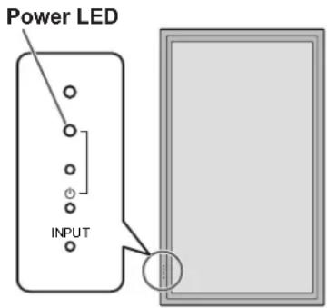
Part Names
■Front view
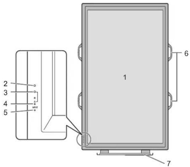
- LCD panel
- Remote control sensor (See page 12.)
- Power LED (See page 14.)
- Power switch (See page 14.)
- Input switch (See page 15.)
- Handles (See page 13.)
- Temporary Stand (See page 13.)
TIPS
- Use a pointed object such as a pen tip to press the switches at the front of the monitor.
■Rear view
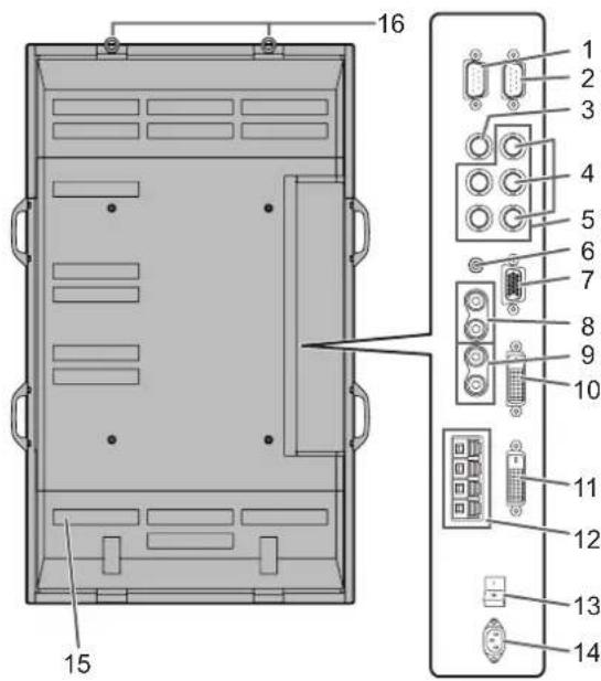
- RS-232C output terminal (D-sub 9 pin) (See page 24.)
- RS-232C input terminal (D-sub 9 pin) (See page 24.)
- AV3 input terminal (BNC) (See page 10.)
- AV2 input terminals (BNC) (See page 10.)
- PC3 input terminals (BNC) (See page 10.)
- PC audio input terminal (See page 10.)
- PC2 input terminal (Mini D-sub 15 pin) (See page 10.)
- AV audio input terminals (See page 10.)
- PC/AV audio output terminals (See page 11.)
- PC1 input terminal (DVI-D) (See page 10.)
AV1 input terminal (DVI-D) (See page 10.) - PC/AV output terminal (DVI-D) (See page 11.)
- External speaker terminals (See page 11.)
- Main power switch(See page 14.)
- AC input terminal (See page 12.)
- Vents
- Hooks
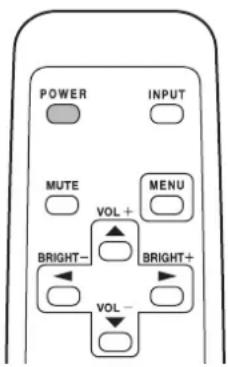
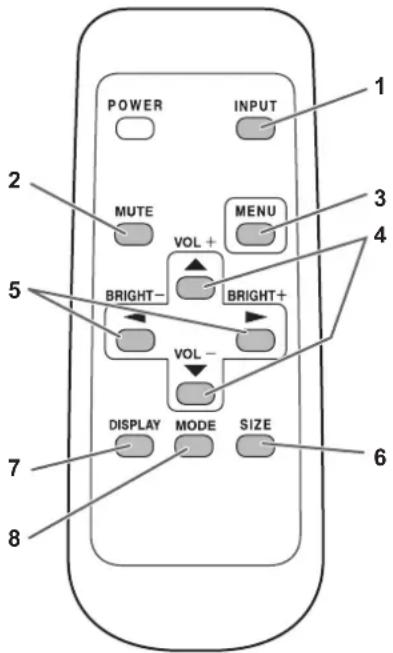
■Remote control unit
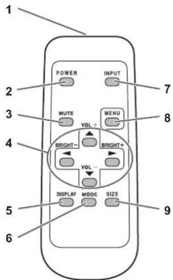
- Signal transmitter
- POWER button (See page 14.)
- MUTE button (See page 15.)
- VOL +/- buttons (See page 15.) BRIGHT +/- buttons (See page 15.) Cursor control (▲ /▼) buttons
- DISPLAY button (See page 15.)
- MODE button (See page 15.)
- INPUT button (See page 15.)
- MENU button (See page 17.)
- SIZE button (See page 15.)
Mounting precautions
- Since the monitor is heavy, consult your dealer before installing, removing or moving the monitor.
- When installing, removing or moving the monitor, ensure that this is carried out by at least 3 people.
- When moving the monitor, be sure to hold it with the handles both on the rear and the unit bottom. Do not hold the LCD panel. This may cause product damage, failure, or injury.
- Install the monitor with the surface perpendicular to a level surface. If necessary, limit the tilt between 0 and 20 degrees downward.
- Mounting the monitor on the wall requires special expertise and the work must be performed by an authorised SHARP dealer. You should never attempt to perform any of this work yourself. Our company will bear no responsibility for accidents or injuries caused by improper mounting or mishandling.
- This monitor should be used at an ambient temperature between 0^ and 40^ . Provide enough space around the monitor to prevent heat from accumulating inside.
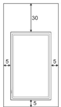
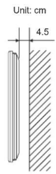
If it is difficult to provide such space because the monitor is installed inside a housing or for other reasons, take other measures to keep the ambient temperature between 0^ C and 40^ C such as installing a fan in the housing.
- This monitor must be installed in a vertical orientation only. It cannot be installed in a horizontal orientation.
- Do not block any ventilation openings. If the temperature inside the monitor rises, this could lead to a malfunction.
- After mounting, it is recommended to take some measures to prevent the monitor from falling down. Secure the monitor by fastening the hooks at the top of the monitor to a wall or a pillar with strong cord and brackets (not included).
- Do not place the monitor on a device which generates heat.
- This monitor is fixed to the temporary stand when shipped from the factory. Please note that this stand is for temporary use only until the monitor is properly mounted.
- Be sure to use a stand or a wall-mount bracket designed or designated for mounting the monitor.
- This monitor is designed to be installed on a concrete wall or pillar. Reinforced work might be necessary for some materials such as plaster / thin plastic board / wood before starting installation.
This monitor and bracket must be installed on a wall which can endure at least 4 times or more the weight of the monitor. Install by the most suitable method for the material and the structure.
Connecting Peripheral Equipment
! Caution
- Be sure to turn off the main power switch and disconnect the plug from the power outlet before connecting/disconnecting cables. Also, read the manual of the equipment to be connected.
- Be careful not to mix up the input terminal with the output terminal when connecting cables. Mixing up the input and output terminals may cause malfunctions and the other problems.
Connection with a PC
PC1 input terminalc  | PC audio input terminal◎ |
PC2 input terminal | |
PC3 input terminals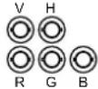 |
- Use a commercially available signal cable (DVI-D 24 pin) for the PC1 input terminal. Set DVI SELECT on the OPTION menu to PC (DIGITAL) when using the PC1 input terminal. (See page 19.)
- Use a commercially available signal cable (Mini D-sub 15 pin) for the PC2 input terminal.
- Use a commercially available signal cable (BNC) for the PC3 input terminals. Set BNC SELECT on the OPTION menu to PC (ANALOG) when using the PC3 input terminals. (See page 19.)
- Use a commercially available audio cable (mini stereo jack) for the PC audio input terminal. Use an audio cable without resistance.
TIPS
- Images may not be displayed properly depending on the computer (graphics board) to be connected.
- A screen with 1920 x 1080 resolution may not be displayed correctly on PC3 (BNC). In this case, check the settings of your computer (graphics board) to verify that input signals conform to specifications of this monitor (Hsync: 66.3 kHz, Vsync: 60 Hz, and Dot frequency: 148.5 MHz). (See page 34.)
- If there is a check box to disable EDID in display control panel, check it when using PC3 (BNC).
- Use the automatic screen adjustment when a PC screen is displayed for the first time using PC2 or PC3, or when the setting of the PC is changed. (See page 22.)
- The screen is adjusted automatically when SELF ADJUST in the OPTION menu is set to "ON". (See page 19.)
Connection with AV equipment
AV1 input terminal | AV audio input terminals◎◎ |
AV2 input terminals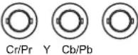 | |
  |
- Use a commercially available signal cable (DVI-D 24 pin) for the AV1 input terminal. Set DVI SELECT on the OPTION menu to AV (DIGITAL) when using the AV1 input terminal. (See page 19.)
- Use a commercially available component cable (BNC) for the AV2 input terminals. Set BNC SELECT on the OPTION menu to AV (COMPONENT) when using the AV2 input terminals. (See page 19.)
- Use a commercially available video cable (BNC) for the AV3 input terminal.
- Use a commercially available audio cable (RCA) for the AV audio input terminals.
- The AV1 input terminal is compatible with the video signals below:
1920 x 1080 p @ 50/59.94/60 Hz
1920 x 1080 i @ 50/59.94/60 Hz
1280 x 720 p @ 50/59.94/60 Hz
720 x 576 p @ 50 Hz
720 x 480 p @ 59.94/60 Hz
640 x 480 p @ 59.94/60 Hz
- The AV2 input terminals are compatible with the video signals below:
1080i (1125i)/50, 1080i (1125i)/60, 720p (750p)/50, 720p (750p)/60, 576p (625p), 576i (625i), 480p (525p), 480i (525i)
Other terminals
PC/AV audio output terminals
- Audio from the equipment connected to the AV audio input terminals or PC audio input terminal is output. Connect to the audio input terminals of the connected equipment using a commercially available audio cable (RCA).
- The audio output varies depending on the input mode selection. (See page 15.)
- The volume level can be adjusted using the volume adjustment. (See page 15.)
- Selecting FIXED of "AUDIO OUTPUT" from the OPTION menu fixes the volume of sound output from the audio output terminals. (See page 19.)
- Audio signals output from the PC/AV audio output terminals cannot be adjusted using the AUDIO menu.
PC/AV output terminals
Video signals from PC1 and AV1 can be output to HDCP-compatible external device. Use this terminal when you connect multiple monitors in a daisy chain via DVI cable (commercially available). (See the description on the right.) Images cannot be output to device that is not HDCP-compatible.
RS-232C input/output terminals
You can control the monitor from a PC by connecting a commercially available RS-232 straight cable between this terminal and the PC. (See page 24.)
Connecting external speakers
Be sure to use external speakers with an impedance of 6 Ω and a rated input of at least 7 W.
(1) (2)
natural_image
Two diagrams showing a mechanical component with arrows indicating direction, no text or symbols present.- While pushing the tab, insert the tip of the cable.
- Release the tab.
TIPS
- Be sure to connect the + and - terminals and the left and right speakers properly.
- Avoid short circuiting the + and - terminals.
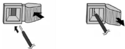
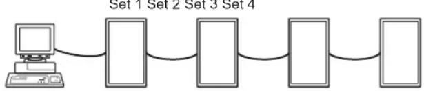
Connecting multiple monitors
You can connect multiple monitors (up to 5 monitors) in a daisy chain by using the PC1/AV1 input terminals and PC/AV output terminals of this monitor.
Connection example
flowchart
graph TD
    A["First monitor"] --> B["PC1/AV1 input terminal"]
    B --> C["PC/AV output terminal"]
    C --> D["Digital signal (DVI) cables (commercially available)"]
    D --> E["To PC digital RGB output terminal"]
    F["Second monitor"] --> G["PC1/AV1 input terminal"]
    G --> H["PC/AV output terminal"]
    H --> I["Digital signal (DVI) cables (commercially available)"]
    I --> J["To PC digital RGB output terminal"]
    style A fill:#f9f,stroke:#333
    style F fill:#f9f,stroke:#333
    style G fill:#f9f,stroke:#333
    style H fill:#f9f,stroke:#333
    style I fill:#f9f,stroke:#333
TIPS
- The length of the signal cables or surrounding environment may affect the image quality.
- The screen may not display properly when using terminals other than PC1/AV1 for the input mode. In this case, turn off the power to all the monitors connected in a daisy chain and then turn the power on again.
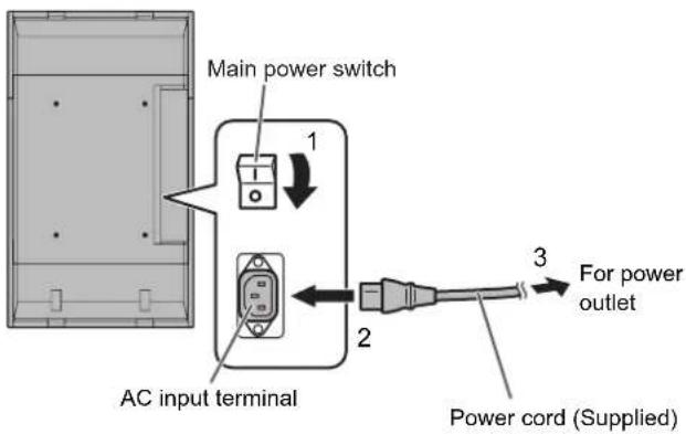
Connecting the Power Cord
! Caution
- Do not use a power cord other than the one supplied with the monitor.
- Turn off the main power switch.
- Plug the power cord (supplied) into the AC input terminal.
- Plug the power cord (supplied) into the AC power outlet.
Preparing the Remote Control Unit
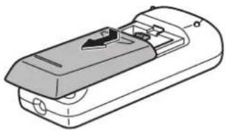
Installing the batteries
- Press the cover gently and slide it in the direction of the arrow.
natural_image
Line drawing of a device casing with internal components and a directional arrow (no text or symbols)-
See the instructions in the compartment and put in the supplied batteries (2 R-6 batteries) with their plus (+) and minus (-) sides oriented correctly.
-
Close the cover.
TIPS
- The supplied batteries (2 R-6 batteries) may become exhausted faster depending on the storage condition. It is recommended that you replace them with new batteries (commercially available) earlier than specified.
- If you will not use the remote control for a long time, remove the batteries.
• Use manganese or alkaline batteries only.
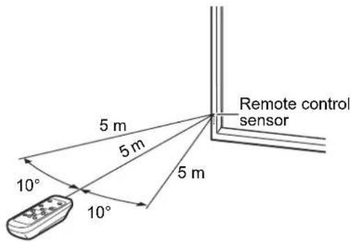
Remote control operation range
The operation range of the remote control unit is approx. 5 m at an angle of approx 10^ from the centre to the top/bottom/right/left of the remote control sensor.
TIPS
- Do not expose the remote control unit to shock by dropping or stepping on it. This could lead to a malfunction.
- Do not expose the remote control unit to liquids, and do not place it in an area with high humidity.
- The remote control unit may not work properly if the remote control sensor is under direct sunlight or strong lighting.
- Objects between the remote control unit and the remote control sensor may prevent proper operation.
- Replace the batteries when they run low as this may shorten the remote control's operation range.
- If a fluorescent light is illuminated near the remote control unit, it may interfere with proper operation.
- Do not use it with the remote control of other equipment such as air conditioner, stereo components, etc.
Removing the Temporary Stand and the Handles
■Removing the Temporary Stand
Prepare wall-hanging brackets or a stand to mount the monitor unit. Read the manual for the brackets or stand for the proper mounting procedure. (The screw holes for mounting brackets (M10 x 4 holes) are provided on the rear of the monitor.)
!Caution
- The monitor is heavy. Make sure to handle the monitor with at least 3 people.
-
This monitor is fixed to the temporary stand when shipped from the factory. Please note that this stand is for temporary use only until the monitor is properly mounted.
-
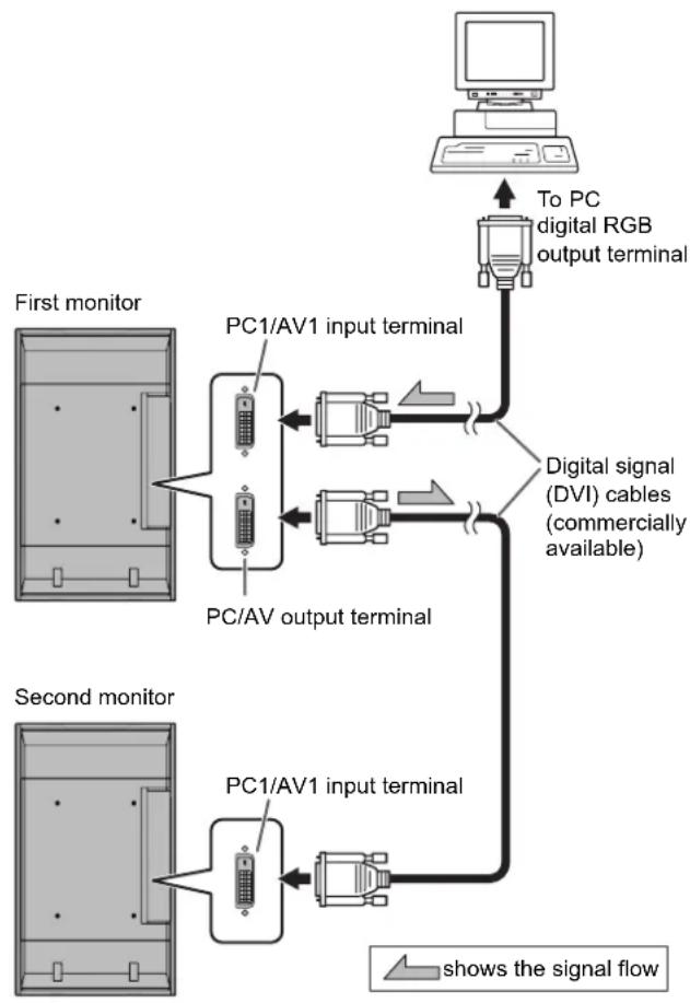
Hold the monitor with the handles to prevent it from falling down, and remove the stand fixing screws (4).
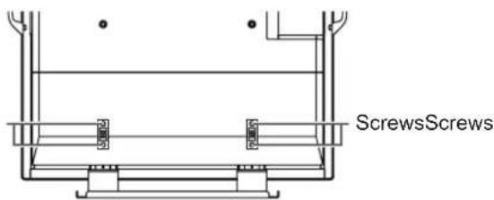
- Lift the monitor by holding it with the handles and the underside of the unit.
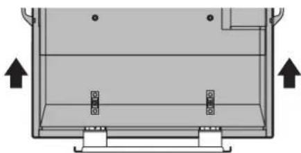
natural_image
Diagram of a mechanical or electrical component with two vertical supports and an upward arrow indicating direction (no text or symbols)- When the installation is complete, attach the included stand hole protection covers, using the supplied screws.
(1) Remove the screws from the monitor unit.
(2) Secure the stand hole protection covers with the screws removed in step (1).
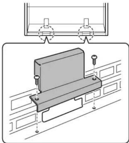
natural_image
Technical illustration of a mechanical assembly with mounting holes and a bracket (no text or symbols)- The temporary stand is specifically designed for this monitor. Do not use for other devices.
■Removing the Handles
The handles are detachable.
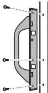
natural_image
Diagram of a door handle assembly with mounting holes and dashed lines indicating alignment (no text or labels)After you removed the handles, be sure to replace the removed screws in the original holes.
Turning Power On/Off
Caution
- Turn on the monitor first before turning on the PC or playback device.
Turning on the main power
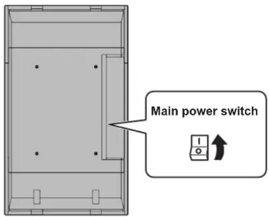
When the main power switch is off, the monitor cannot be turned on using the POWER button on the remote control unit.
Turning power on/off
Press the POWER button to turn the power ON/OFF.
| Status of a power LED Status of the monitor | |
| Green lighting Power “On” | |
| Orange lighting Power “Off” (Standby mode) | |
| Green flashing | Input signal standby mode(input using a PC) |
! Caution
- When switching the main power switch or the POWER button off and back on, always wait for at least 5 seconds. A short interval may result in a malfunction.
TIPS
- If the monitor is in the input signal standby mode and you press the POWER button on the remote control unit, the monitor enters standby mode.
- You can turn on/off the monitor by pressing the power switch of the monitor.
- Setting the SCHEDULE flashes the power LED alternately in red and orange in standby mode.
Date/time setting
- If the time has yet to be set when the monitor is first turned on, the date/time setting screen appears. Set the date and time.
![DATE/TIME SETTING SET 20 07 / 01 / 01 00 : 00 CANCEL OK…[MENU]](/content/2026/02/367675/images/44c2d8d6cdc84fd3bb590de6fbaa92243a7e191f9eb8170a0fb0142371eba4a4.jpg)
- Press , or to select the date and time, and press or to change the numerical values.
- Select SET and then press MENU.
- Be sure to set the date and time.
- The date/time setting screen will close automatically if no operation is performed for about 15 seconds. The date and time can be set using DATE/TIME SETTING from the OPTION menu when the date/time setting screen disappears.
TIPS
- Set the date in "Year/Month/Day" order.
- Set the time on a 24-hour basis.
- The clock stops after the power-off status continues for approximately 1 week.* The date/time setting screen appears at power-on. Be sure to set the date and time. (* This is a guide. The power-off status that stops the clock depends on the status of the monitor.)
Disabling power on/off operations
Power on/power off operations can be disabled in order to protect the monitor from an accidental power off. Set the ADJUSTMENT LOCK in FUNCTION menu to "2". (See page 23.)
Basic Operation
1. INPUT (Input mode selection)
The menu is displayed. Press or to select the input mode, and press to enter.
* You can select the input terminal by pressing the input switch of the monitor.
| Input mode Video | Audio | |
| PC1 DIGITAL ^1 | PC1 input terminal | PC audio input terminal |
| PC2 ANALOG | PC2 input terminal | |
| PC3 ANALOG ^2 | PC3 input terminals | |
| AV1 DIGITAL ^1 | AV1 input terminal | AV audio input terminals |
| AV2 COMPONENT ^2 | AV2 input terminals | |
| AV3 VIDEO AV3 input terminal | ||
*1 Select the terminal for DVI SELECT. (See page 19.)
*2 Select the terminal for BNC SELECT. (See page 19.)
2. MUTE
Turns off the volume temporarily.
Press the MUTE button again to turn the sound back to the previous level.
3. MENU
Displays and turns off the menu screen (see page 17).
4. VOL +/- (Volume adjustment)
Pressing or displays the VOLUME menu when the menu screen is not displayed.

Press or to adjust the volume of the sound.
* If you do not press any buttons for about 4 seconds, the VOLUME menu automatically disappears.
5. BRIGHT +/- (Backlight adjustment)
Pressing or displays the BRIGHT menu when the menu screen is not displayed.

Press or to adjust the brightness.
* If you do not press any buttons for about 4 seconds, the BRIGHT menu automatically disappears.
6. SIZE (Screen size selection)
The menu is displayed.
Press or to select the screen size. (See page 16.)
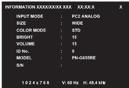
7. DISPLAY
Displays monitor information. The display disappears when this button is pressed again or disappears automatically after approximately 15 seconds.
8. MODE (Colour mode selection)
Each time you press this button, the colour mode changes in the following order:
$$ \text { STD (Standard) } \rightarrow \text { VIVID } \rightarrow \text { sRGB } \rightarrow \text { STD... } $$
- sRGB applies to PC input only. sRGB is international standard of colour representation specified by IEC (International Electrotechnical Commission). Colour conversion is made in taking account of liquid crystal's characteristics and represents colour tone close to its original image.
■Switching the screen size
Even when the screen size is changed, the display may remain the same depending on the input signal.
WIDE PC input Displays image  | so it fills the entire screen. | |
| AV input An image with a 4:3 aspect ratio is stretched to fill the entire screen. | ||
ZOOM 1 PC input An image with  | a 4:3 aspect ratio is enlarged to fill the entire screen without changing the aspect ratio. The edges of the image may be cut off. | |
| AV input | ||
ZOOM 2 PC input Use this size  | if ZOOM 1 cuts off the subtitles. | |
| AV input | ||
NORMAL PC input Displays image  | age so it fills the screen without changing the aspect ratio of the input signals. | |
| AV input | Displays the entire image of the aspect ratio of 4:3 without changing the aspect ratio. | |
DotbyDot PC input Displays the dots of the signals input from the connected PC as the corresponding dots on the screen. *  | AV input | Displays the dots of the input signals as the corresponding dots on the screen. |
*: With a monitor with a screen resolution of 1600 x 1200, selecting DotbyDot displays the NORMAL screen.
TIPS
- Using this monitor's screen-size switching or dual-screen display functions to compress or expand the screen for commercial or public viewing in establishments like cafes or hotels may infringe on the rights of the creators, as protected by Copyright Law, so please be careful.
- When "Enlarge" is set, the screen size is fixed to "WIDE" mode.
- When dual-screen display is selected, the screen size cannot be changed.
- The appearance of the original video may change if you select a screen size with a different aspect ratio than the original image (e.g. TV broadcast or video input from external equipment).
- When an ordinary non-wide image (4:3) is viewed with the whole screen using the screen-size switching function of this monitor, the edge of the image may be lost or appear distorted. If you wish to respect the creator's intentions, set the screen size to "NORMAL".
- When playing commercial software, parts of the image (like subtitles) may be cropped. In this case select the optimal screen size using the screen-size switching function of this monitor. With some software, there may be noise or distortion at the edges of the screen. This is due to the characteristics of the software, and is not a malfunction.
- Depending on the original image size, black bands may remain at the edges of the screen.
Displaying the menu screen
Video and audio adjustment and settings of various functions are enabled. This section describes how to use the menu items. See pages 18 to 20 for details of each menu items.
■Example of operation
(Adjusting CONTRAST in the PICTURE menu)
- Press ☐ to display the menu screen.
![SCREEN PC2 ANALOG1/1 AUTO CLOCK 127 PHASE 31 H-POS 31 V-POS 150 RESET END...[MENU] 1 0 2 4 x 7 6 8 V: 60 Hz H: 48.4 kHz](/content/2026/02/367675/images/8810869a3c28d6e8e80702e22fbf56ad975e2d4066e6930020110a06733086d5.jpg)
-
Press ▲ or ▼ to select PICTURE, and press ▲ PICTURE menu is displayed.
-
Press ▲ or ▼ to select CONTRAST.
![SCREEN PICTURE AUDIO SETUP OPTION ENLARGE PIP/PbYP PICTURE AUTO CONTRAST 30 BLACK LEVEL 96 SHARPNESS 12 (PC2 ANALOG1)2 OK...[MENU] 1 0 2 4 x 7 6 8 V: 60 Hz H: 48.4 kHz](/content/2026/02/367675/images/289b7dfaef3fe01f9e5f5bd374a5ff73c6a5852601c1d6f03a13c550087d30e6.jpg)
- Press or to adjust the setting.
![SCREEN PICTURE AUDIO SETUP OPTION ENLARGE PIP/PbyP PICTURE AUTO CONTRAST 40 BLACK LEVEL 96 SHARPNESS 12 (PC2 ANALOG1)2 OK...[MENU] 1 0 2 4 x 7 6 8 V: 60 Hz H: 48.4 kHz](/content/2026/02/367675/images/bd090aee6b394ad6e7527e11c63d6667dc05f2c55293c2c7775619d5c415b9a4.jpg)
For items that have ▶press, make settings and then press MENU.
- Press ☐ twice to close the menu screen.
TIPS
- The menu will differ depending on the input mode.
- The menu screen will close automatically if no operation is performed for about 15 seconds. (DATE/TIME SETTING and SCHEDULE screens will close in about 4 minutes.)
■Menu screen display
![SCREEN PICTURE AUDIO SETUP OPTION ENLARGE PIP/PbyP 1 3 2 4 (PC2 ANALOG1)2 PICTURE AUTO CONTRAST 30 BLACK LEVEL 96 SHARPNESS 12 1 0 2 4 x 7 6 8 V: 60 Hz H: 48.4 kHz OK...[MENU]](/content/2026/02/367675/images/9c60fa42c582b6da77aa0b3a6adaac5d1a0e681c9968d460d02c74816713bcb3.jpg)
1 Name of the menu
2 Input mode
3 An item being selected (highlighted)
4 Screen resolution of input signal, and other data.
TIPS
- Items that cannot be selected appear in grey. (e.g. Function not supported by the current input signal)
Menu item details
The menu will differ depending on the input mode.
■SCREEN (PC2/PC3)
AUTO
The CLOCK, PHASE, H-POS, and V-POS are automatically adjusted.
Pressing ▶ performs adjustment.
Use this automatic adjustment when you use the PC2 input terminal or PC3 input terminals to display a PC screen for the first time or when you change the setting of the PC. (See page 22.)
CLOCK
Adjusts frequency for sampling clock for applicable video. Adjust when there is flickering in the form of horizontal stripes.
When using the adjustment pattern (see page 22), make adjustments so that no horizontal stripe noise appears in it.
PHASE
Adjusts sampling clock phase for applicable video.
Useful when small characters appear with low contrast and/or there are flickers at corners.
When using the adjustment pattern (see page 22), make adjustments so that no vertical stripe noise appears in it.
* Adjustments to PHASE should be made only after CLOCK has been correctly set.
H-POS
Adjust the horizontal position of the image.
V-POS
Adjust the vertical position of the image.
RESET
Resets the values of the SCREEN menu items to the factory preset values.
Select "ON" and then press MENU
■PICTURE
AUTO (PC2/PC3)
The CONTRAST and BLACK LEVEL are automatically adjusted.
Pressing ▶ performs adjustment.
CONTRAST
Adjusts the brightness of the image.
BLACK LEVEL
Adjusts the entire brightness of the video signals.
TINT (AV input)
Adjusts the hue. Selecting + changes the colour towards green, and selecting - changes it towards magenta.
COLORS (AV input)
Adjusts the colour intensity.
SHARPNESS
Adjusts the sharpness of the image.
ADVANCED (AV input)
You can adjust more specifically. (See page 22.)
COLOR MODE
Changes the colour mode on the screen. The colour mode on the screen can also be changed using a remote control unit. (See page 15.)
* sRGB is PC input only. See page 15 for details.
WHITE BALANCE
THRU ...... Displays the input signal level as is. (for PC1 only)
PRESET ...... Selects the colour temperature using PRESET.
USER .... Used for adjusting R-CONTRAST, G-CONTRAST, and B-CONTRAST respectively.
PRESET
Selects the colour temperature when the WHITE BALANCE is set to PRESET.
R-CONTRAST
Adjusts red component when the WHITE BALANCE is set to USER.
G-CONTRAST
Adjusts green component when the WHITE BALANCE is set to USER.
B-CONTRAST
Adjusts blue component when the WHITE BALANCE is set to USER.
COPY TO USER
Copies the value set for PRESET to the USER setting.
Select "ON" and then press MENU.
GAMMA
Select a gamma value.
RESET
Resets the values of the PICTURE menu items to the factory preset values.
Select "ON" and then press MENU.
AUDIO
TREBLE
Adjusts the volume of treble-level sound.
BASS
Adjusts the volume of bass-level sound.
BALANCE
Adjusts the balance of the audio sound between right and left.
RESET
Resets the values of the AUDIO menu items to the factory preset values. Select "ON" and then press MENU.
SETUP
OSD H-POSITION
Adjusts the horizontal display position of menu screen.
OSD V-POSITION
Adjusts the vertical display position of menu screen.
LANGUAGE
Sets the display language for the menu screen.
ID No. SET
Assigns ID numbers to monitors connected in a daisy chain (see page 25), using RS-232 cables.
The numbers 1 to 255 are available for ID numbers.
If "0" is set, the system regards this as the state where no ID number is set.
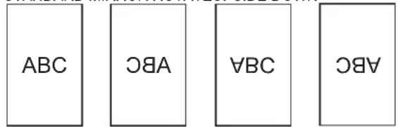
PICTURE FLIP
A picture flips to appear.
STANDARD MIRROR ROTATE UPSIDE DOWN
POWER ON DELAY
You can delay the screen display after the monitor is turned on. The period can be set up to 60 seconds in units of one second. When this function is activated, the power LED flashes (at approx. 1 second interval) in orange. This function is disabled when 0 is specified.
OPTION
DATE/TIME SETTING
Set the date and time. Press or ▶ to select the date and time, and press ▶ or ▶ to change the numerical values.
Set the date in "Year/Month/Day" order.
Set the time on a 24-hour basis.
SCHEDULE (See page 21.)
You can set the time to switch the monitor on and off.
DVI SELECT
Selects equipment that is to be connected to the PC1/AV1 input terminal.
BNC SELECT
Selects equipment that is to be connected to the PC3/AV2 input terminals.
QUICK SHOOT
Reduces the visual lag inherent in fast-motion scenes.
COLOR SYSTEM
Select the colour system of the AV equipment which is connected to AV3 input terminal. (AUTO / PAL / PAL-60 / SECAM / NTSC3.58 / NTSC4.43)
When AUTO is selected, the colour system is automatically set according to the input signal.
AUDIO OUTPUT
Sets the volume of sound output from the PC/AV audio output terminals.
VARIABLE ...... You can adjust the volume using VOLUME. FIXED ...... Fixes the sounds.
480LINES (PC2/PC3)
If a computer connected to the PC2/PC3 input terminal has a resolution of 640 x 480 or 848 x 480, make a selection according to the resolution.
768LINES (PC2/PC3)
If a computer connected to the PC2/PC3 input terminal has a resolution of 1024 x 768, 1280 x 768 or 1360 x 768, make a selection according to the resolution.
SELF ADJUST
On a PC2/PC3 screen with a resolution of 800 x 600 or higher, specify whether to perform screen adjustment automatically or not. When ON is selected, the screen is automatically adjusted when the timing of input signals varies. "ADJUSTING" appears on the screen during the adjustment.
POWER MANAGEMENT
POWER MANAGEMENT determines whether or not to switch modes from no signal to the input signal standby mode when the PC screen is displayed.
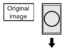
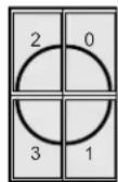
■ENLARGE (PC input)
ENLARGE MODE
Sets the number of screen splits used for the enlargement. (See page 21.)
ENLARGE POS
Specify the split screen to be displayed when the enlargement function is used. (See page 21.)
BEZEL H / BEZEL V
Sets the frame width of the display when the enlargement function is used.
H-POS
Adjust the horizontal position of the enlarged screen.
V-POS
Adjust the vertical position of the enlarged screen.
■PIP/PbyP
PIP MODES
Sets the display method.
OFF ......Displays one screen.
PIP ......Displays a sub screen inside a main screen.
PbyP ......Displays a main screen and a sub screen in a line.
PbyP2 .....Displays a main screen which measures 1280 pixels in the longest direction and a sub screen in a line.
PIP SIZE
Sets the size of the sub screen in PIP mode.
PIP H-POS
Adjusts the horizontal position of the sub screen in PIP mode.
PIP V-POS
Adjusts the vertical position of the sub screen in PIP mode.
PIP BLEND
In PIP mode, use this menu item to display the sub screen transparently.
PIP SOURCE
Selects the input signal of the sub screen in PIP, PbyP, or PbyP2 mode.
SOUND CHANGE
Sets the sound which is output in PIP, PbyP, or PbyP2 mode. If the main screen is displayed as a full screen by the AUTO OFF function, the sound for the main screen is output even when the sound for the sub screen is specified.
MAIN POS
Sets the position of the main screen in PbyP or PbyP2 mode.
PbyP2 POS
Sets the position of the sub screen in PbyP2 mode.
AUTO OFF
Sets the display method when no signals for the sub screen are input in PIP, PbyP, or PbyP2 mode.
MANUAL ..... Displays a main screen and a black sub screen.
AUTO ......Displays the main screen as a full screen.
TIPS
- When WHITE BALANCE is set to THRU, BLACK LEVEL, CONTRAST and GAMMA cannot be set.
- If COLOR MODE is set to sRGB or VIVID, the following items cannot be set. WHITE BALANCE, PRESET, R-/G-/B-CONTRAST, COPY TO USER, and GAMMA
■Dual screen display
You can display the screens of the PC input signal and AV input signal simultaneously.
Set this function with "PIP MODES" in the PIP/PbyP menu.
| PIP | A sub screen is displayed inside a main screen. | |
| PbyP | A main screen and a sub screen are displayed in a line. | |
| PbyP2 | Displays a main screen which measures 1280 pixels in the longest direction and a sub screen in a line. |
* The currently selected input signal is displayed on the main screen.
* You cannot simultaneously display the screens of signals of the same type, such as two types of PC input signals or two types of AV input signals.
TIPS
- You might infringe on a copyright of the author which is protected by copyright law when you display the images of the computer screen and television/VCR simultaneously for profit-making or to show the image to the public.
- The screen size for dual-screen display is the same as the screen size for single-screen display. The DotbyDot screen is displayed in NORMAL size except when it is set as the PIP main screen.
- When dual-screen display is selected, the screen cannot be enlarged.
- When dual-screen display is selected, the following adjustments of ADVANCED are invalid and adjusting is disabled.
3D-NR, MPEG-NR and 3D-Y/C
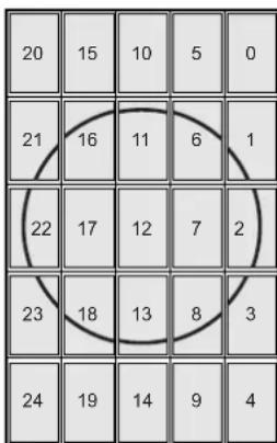
■Enlarge
You can align 4, 9, 16, or 25 monitors and integrate them into a single large screen to display.
Enlarged views of separated images are displayed in each monitor.
4 monitors 9 monitors

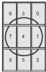
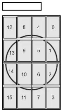
25 monitors16 monitors
TIPS
- AV input signals cannot be used for the Enlarge function.
- To integrate 9 or more monitors using PC1 signals, a splitter for the video signal (commercially available) is required.
- When connected in PC2/PC3, a splitter for the video signal (commercially available) is required.
■SCHEDULE
You can set the time to switch the monitor on and off. Set this function with "SCHEDULE" in the OPTION menu. (See page 19.)
![SCHEDULE XXXX/XX/XX XXX XX:XX:XX No. PO(1) DAY OF TIME WEEK TIME INPUT (3) (4) (5) 1 - - - - - - - - - - - - - - - 2 - - - - - - - - - - - - - - - 3 - - - - - - - - - - - - - - 4 - - - - - - - - - - - - - - - 5 - - - - - - - - - - - - - - 6 - - - - - - - - - - - - - - 7 - - - - - - - - - - - - - 8 - - - - - - - - - - - - - 1 0 2 4 x 7 6 8 V: 60 Hz H: 48.4 kHz OK...[MENU]](/content/2026/02/367675/images/962ef7c3734dcf78b3c9b688de25c46eb95177126c5fbc307b427f300baf01b8.jpg)
- Press on to select the SCHEDULE number, and press ▶
- Set the SCHEDULE. (See the description below.)
Press or to select items, and press or to change the setting.
- Press MENU
SCHEDULE becomes effective.
(1)
- SCHEDULE effective
-: SCHEDULE not effective
(2) POWER
ON : Switches the monitor on at the specified time. OFF : Switches the monitor off at the specified time and puts the monitor in standby mode.
(3) DAY OF THE WEEK
Specifies the day of the week to execute the SCHEDULE. ONLY ONCE:
Executes the SCHEDULE once on the specified day. Specify the day of the week to execute the SCHEDULE.
EVERY WEEK:
Executes the SCHEDULE on the specified day of the week every week. Specify the day of the week to execute the SCHEDULE.
Periodic setting such as "Monday through Friday" is also possible.
EVERY DAY:
Executes the SCHEDULE every day regardless of the day of the week.
(4) TIME
Specifies the time to execute the SCHEDULE. Set the time on a 24-hour basis.
(5) INPUT
Specifies the input mode at power-on. When not specifying, the screen at the previous power-off appears. Input modes displayed on "PC1/AV1" depend on DVI SELECT settings. Input modes displayed on "PC3/AV2" depend on BNC SELECT settings.
! Caution
- Do not switch off the main power after setting the SCHEDULE.
- Specify the correct date and time. (See pages 14 and 19.) SCHEDULE does not function unless the date and time are specified.
- Check regularly that the set date and time are correct.
TIPS
- Up to 8 SCHEDULE items can be registered.
- Setting the SCHEDULE flashes the power LED alternately in red and orange in standby mode.
- A SCHEDULE that has a large number has precedence over that of a small number when schedules overlap.
■ADVANCED items (AV input) (See page 18.)
FLESH TONE
Adjust the hue control.
3D-NR
Reduce the noise of playback images on video.
Setting a higher level reduces more noise. However, it may cause blurring on an image.
MPEG-NR
Reduce block noise caused by digital compression.
3D-Y/C (AV3)
Specify whether to perform 3-dimension Y/C separation. If dot interference or cross-colour is occurring in fast-motion scenes, selecting "OFF" may improve the image quality.
Adjustments for PC screen display
■Automatic adjustment
When you use the PC2 input terminal or PC3 input terminals to display a PC screen for the first time, or when you change the setting of the PC, use the automatic screen adjustment.
- Switch the input to PC2 or to PC3 and display the adjustment pattern. (See the description below.)
- Press MENU and use or to display the SCREEN menu.
- Press ▶ and select "AUTO".
- Press
The automatic adjustment is complete in several seconds.
- Press MENU twice to close the menu screen.
TIPS
- If the screen cannot be adjusted properly with one automatic adjustment, repeat the automatic adjustment two or three times. Try manual adjustment if necessary.
■Screen display for adjustment
Before making adjustments in the SCREEN menu or PICTURE menu, display an image to brighten the entire screen. If you are using a Windows PC, use the adjustment pattern on the supplied CD-ROM.
Opening the adjustment pattern
- Load the supplied CD-ROM into the computer's CD-ROM drive.
- Open the CD-ROM in [My Computer].
- Double-click [Adj_uty.exe].
The adjustment pattern will appear.
Adjust the screen automatically or manually.
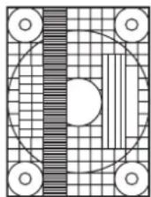
- When adjustment is finished, press the [Esc] on the computer's keyboard to quit the adjustment programme.
- Eject the CD-ROM from the CD-ROM drive.
TIPS
- If the display mode on the computer you are using is 65,000 colours, the colour levels in the colour pattern may appear differently or greyscale may appear to be coloured. (This is due to the specifications of the input signal and is not a malfunction.)
Initialisation (Reset)/Functional Restriction Setting
You can return the settings to their factory-preset values and restrict operations.
1. After pressing SIZE for about 5 seconds, press , , and in that order.
![FUNCTION 1/1 ▶ ALL RESET ⇒ ADJUSTMENT LOCK OFF ▶ OSD DISPLAY ON ▶ LED ON ▶ RS-232C UNLOCKED ▶ END…[MENU]](/content/2026/02/367675/images/a80d88879e455f9da04e8501a723b452ef893171ad41514c7cb4d8f790e46e72.jpg)
2. Select and set the items.
ALL RESET
Resets the settings to the factory default settings.
Press ▶, select "ON" and then press MENU.
After initialisation, turn the main power switch off and then back on.
ADJUSTMENT LOCK
You can disable operations on the monitor and the remote control unit that use buttons.
OFF ...Enables operation.
1 ......Disables all operations other than turning power on/off and FUNCTION.
2 ...... Only the FUNCTION operation is enabled. Disables all operations other than FUNCTION (not even power on/off).
OSD DISPLAY
Hides/shows menus.
The FUNCTION screen cannot be hidden.
ON ......Displays the menus.
OFF ......Hides the menus.
LED
Specifies whether to light power LEDs.
ON .....Lights power LEDs.
OFF .....Does not light power LEDs.
RS-232C
Specifies whether to allow control via RS-232C (see page 24).
LOCKED ......Disables control via RS-232C.
UNLOCKED......Enables control via RS-232C.
3. Press ☐ to return to the normal screen.
Controlling the Monitor with a PC
You can control this monitor from a PC via RS-232C (COM port) on the PC.
You can also connect multiple monitors via a daisy chain by using a PC. By assigning ID numbers to each monitor (see page 25), you can make input mode selection/adjustment or can check the status of a specific monitor.
PC connection
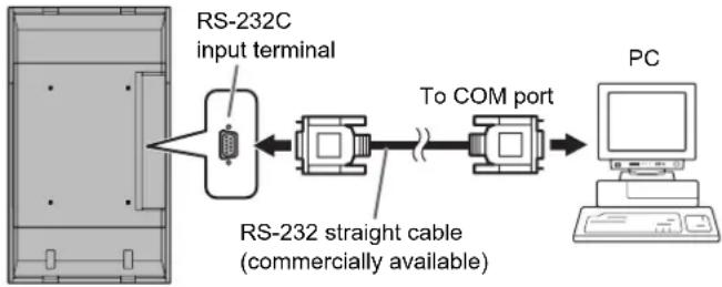
■One-to-one connection with a PC
Connect with RS-232 straight cable between the PC's COM port (RS-232C connector) and the RS-232C input terminal on the monitor.
flowchart
graph LR
    A["RS-232C input terminal"] --> B["RS-232 straight cable (commercially available)"]
    B --> C["To COM port"]
    C --> D["PC"]
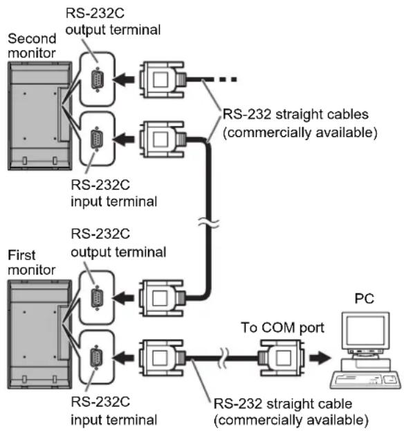
■Daisy chain connection... Advanced operation
Connect with RS-232 straight cable between the PC's COM port (RS-232C connector) and the RS-232C input terminal on the first monitor.
Next, connect RS-232 straight cable to the first monitor's
RS-232C output terminal and to the second monitor's
RS-232C input terminal. Connect in the same way to the third and subsequent monitors.
Up to 25 monitors can be connected. (Depending on the length of the cable used and the surrounding environment.)
flowchart
graph TD
    subgraph First monitor
        A["Second monitor"] --> B["RS-232C output terminal"]
        A --> C["RS-232C input terminal"]
        D["First monitor"] --> E["RS-232C output terminal"]
        D --> F["RS-232C input terminal"]
    end

    subgraph Second monitor
        G["Second monitor"] --> H["RS-232C output terminal"]
        G --> I["RS-232C input terminal"]
        J["First monitor"] --> K["RS-232C output terminal"]
        J --> L["RS-232C input terminal"]
    end

    subgraph PC
        M["PC"] --> N["RS-232 straight cable (commercially available)"]
    end

    B <--> I
    C <--> J
    E <--> K
    F <--> L
    H <--> G
    I <--> H
    K <--> K
    style First monitor fill:#f9f,stroke:#333
    style Second monitor fill:#ccf,stroke:#333
Communication conditions
Set the RS-232C communication settings on the PC to match the monitor's communication settings as follows:
| Baud rate 9600 | bps | Stop bit | 1 bit |
| Data length 8 bits Flow control | None | ||
| Parity bit None | |||
Communication procedure
■Command format
When a command is sent from the PC to the monitor, the monitor operates according to the received command and sends a response message to the PC.
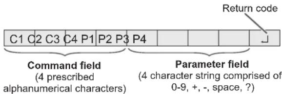
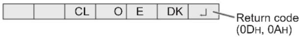
Example: VOLM0030
VOLM 30
* Be sure to input 4 characters for the parameter. Pad with spaces (“”) if necessary.
("☐ is a return code (0D H, 0AH or 0DH))
Wrong : VOLM30
Right : VOLM 30
When inputting a negative value, specify a numerical value in three digits.
Example: AUTR-009
Do not use spaces for MPOS, DATE, and SC01 through SC08. Specify parameters using a specified number of characters.
Example: MPOS010097
If a command has "R" listed for "DIRECTION" in the
"RS-232C command table" on page 28, the current value can be returned by using "?" as the parameter.
Example:
| VOLM ? ? ? ? | ← From PC to monitor (How much is current volume setting?). |
| 30 | ← From monitor to PC (Current volume setting: 30). |
* If an ID number (see page 25) has been assigned (For example, ID number = 1).
| VOLM _ _ ? ← | From PC to monitor. |
| 30 _001 ← | From monitor to PC. |
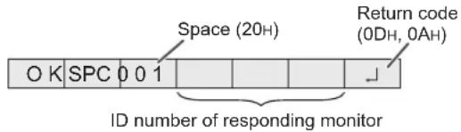
■Response code format
When a command has been executed correctly
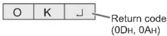
A response is returned after a command is executed.
* If an ID number has been assigned
When a command has not been executed
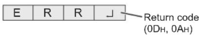
* If an ID number has been assigned
TIPS
- "ERR" is returned when there is no relevant command or when the command cannot be used in the current state of the monitor.
- If communication has not been established for reasons such as a bad connection between the PC and monitor, nothing is returned (not even ERR).
- If no monitor has been assigned the designated ID number (e.g. if the command IDSL0002 is used, but no monitor with ID number: 2 is found), no response is returned.
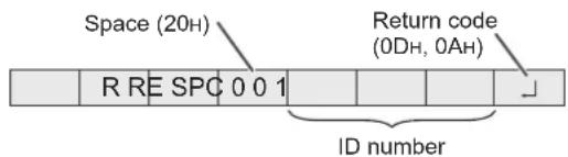
If execution of the command is taking some time
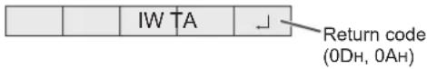
When the following commands are used, "WAIT" is returned. In this case, a value will be returned if you wait a while. Do not send any command during this period.
No ID number is attached to WAIT response.
- Commands which return WAIT:
- When repeater control is used
- When an IDSL or IDLK command is used
- When one of the following commands is used: RSET, INPS, ASNC, WIDE, EMAG, EPOS, PXSL, POWR, AGIN, MWIN, MWIP, MWPP, ESTG
When control via RS-232C is locked (to prevent use) using the operation lock function (see page 23)
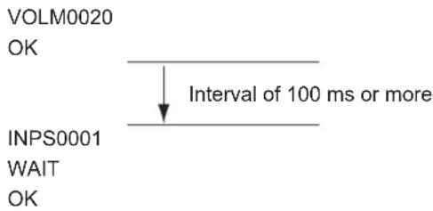
■Communication interval
- After OK or ERR is returned, you must send the following commands.
To set a timeout for the command response, specify 10 seconds or longer. - Provide an interval of 100 ms or more between the command response and the transmission of the next command.
Advanced operation
This section explains commands for daisy chain connection. The basic communication procedure is the same as in the "One-to-one connection with a PC" section.
ID numbers
You can assign a unique ID number to each monitor (see page 19). This allows you to control a particular monitor in a daisy chain of monitors. You can assign ID numbers either from the menu screen (using the remote control) or from the PC using RS-232 cable.

flowchart
graph LR
    A["Computer"] --> B[" "] --> C[" "] --> D[" "] --> E[" "]
If monitors are connected as shown above, you can execute commands like "Set the volume of the monitor with ID 4 to 20".
When controlling monitors linked in a daisy chain by designating ID numbers, you should basically avoid any duplication of ID numbers.
ID numbers do not have to be assigned in ascending order starting from the PC. They can also be connected as shown below.
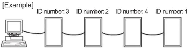
flowchart
graph LR
    A["Computer"] --> B["ID number: 3"]
    B --> C["ID number: 2"]
    C --> D["ID number: 4"]
    D --> E["ID number: 1"]
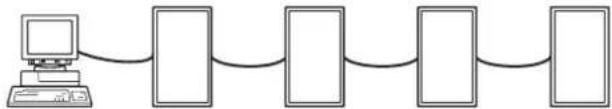
Controlling the Monitor with a PC
■Commands for ID control
The command examples shown on this page assume the following connection and ID number set up.
ID number: 1 ID number: 2 ID number: 3 ID number: 4

flowchart
graph LR
    A["Computer"] --> B["Rectangle"]
    B --> C["Rectangle"]
    C --> D["Rectangle"]
    D --> E["Rectangle"]
IDST ...... A monitor receiving this command sets its own ID number in the parameter field.
Example:
IDST0001
OK 001 ←
The ID number of this monitor is set to 1.
TIPS
You can automatically assign ID numbers by using the IDST command with the Repeater control (see "Repeater control" on page 27).
For example, using the command "IDST001+" automatically sets the ID numbers, as shown below.
[Example]
ID number: 1 ID number: 2 ID number: 3 ID number: 4
flowchart
graph LR
    A["Computer"] --> B["Rectangle"]
    B --> C["Rectangle"]
    C --> D["Rectangle"]
    D --> E["Rectangle"]
IDST001 + ←
ID setting command with repeater control
WAIT
OK 001 ←
"OK" response from ID number: 1
OK 002 ←
"OK" response from ID number: 2
OK 003 ←
"OK" response from ID number: 3
OK 004 ←
"OK" response from ID number: 4 (End)
IDSL .....The parameter of this command sets the ID number of the monitor. The monitor is subject to the next command.
Example:
IDSL0002 ←
The next command is for the monitor with ID number: 2.
WAIT ←
Searching for monitor with ID number: 2.
OK 002 ←
Found monitor with ID number: 2.
VOLM0030 ←
Sets volume of monitor with ID number: 2 to 30.
WAIT ←
Processing.
OK_002←
OK response from monitor with ID number: 2.
VOLM0020←
Sets volume to 20.
OK 001 ←
The volume of the monitor with ID number: 1 (the one directly connected to the PC) is set to 20.*
* The IDSL command is effective only once, for the immediately succeeding command.
IDLK ......The parameter of this command sets the ID number of the monitor. The monitor is subject to all subsequent commands.
Example:
IDLK0002 ←
Following commands are for the monitor with ID number: 2.
WAIT ←
Searching for monitor with ID number: 2.
OK 002 ←
Found monitor with ID number: 2.
VOLM0030
Sets volume of monitor with ID number: 2 to 30.*
WAIT ←
Processing.
OK_002
VOLM0020
← Sets volume of monitor with ID number: 2 to 20.*
WAIT
OK 002
IDLK0000 ←
Canceling fixed ID number setting.
WAIT ←
Canceling IDLK.
OK 002 ←
Cancelation complete.
VOLM0010
OK 001 ←
The volume of the monitor with ID number: 1 (the one directly connected to the PC) is set to 10. (IDLK is canceled.)
* The IDLK command remains effective until it is canceled, or power is shut off.
IDCK.....Provides screen display of the ID number currently assigned to a monitor, and the ID number currently set for IDLK (if any).
Example:
(After executing IDLK0002)
IDCK0000
← (Parameter has no meaning.)
Returned response. The ID
ID:001 IDLK:002
← number is also displayed on the monitor screen.
IDCK000 +
← Repeater control (If a command is used with repeater control, ID designation using IDSL or IDLK is canceled.).
WAIT
ID:001 IDLK:000
ID:002 IDLK:000
ID:003 IDLK:000
ID:004 IDLK:000
■Repeater control
This system has a function to allow setting of multiple monitors connected in a daisy chain using a single command. This function is called repeater control. You can use Repeater control function without assigning ID numbers.
[Example]
flowchart
graph LR
    A["Computer"] --> B["Set 1"]
    B --> C["Set 2"]
    C --> D["Set 3"]
    D --> E["Set 4"]
* If monitors are connected as shown above, you can execute a command like "Set all monitors' input settings to PC1 DIGITAL".
■Repeater control command
Repeater control is achieved by setting the FOURTH CHARACTER of the parameter to “+”.
Example:
VOLM030 + ←
Sets volume of all monitors to 30.
In repeater control, responses are returned by all the connected monitors.
If you want to determine that a value has been returned by a specific set, assign ID numbers to each monitor in advance. When some monitors do not return their responses, the probable cause is that the monitors could not receive the command or command processing is not complete. Do not send a new command.
Example: (When 4 monitors are connected, and assigned ID numbers: 1 through 4.)
VOLM030 +
WAIT
OK_001
OK_002
OK 003
OK_004 ← If 4 monitors are connected in
a chain, reliable operation can be ensured by sending a new command only after a reply has been returned by 4th (last) monitor.
Repeater control can also be used for reading settings.
Example:
VOLM ? ? ? +
WAIT
10 001
20 002
30 003
30 004
Volume settings for all monitors are returned.
TIPS
- If repeater control is used during ID designation (IDSL, IDLK), the ID designation is canceled.
- Commands that use parameters consisting of more than four characters can not be controlled by repeater control.
RS-232C command table
How to read the command table
Command: Command field (See page 24.)
Direction: W When the "Parameter" is set in the parameter field (see page 24), the command functions as described under "Control/Response Contents".
R The returned value indicated under "Reply" can be obtained by setting "?????", "(repeater control) in the parameter field (see page 24).
Parameter: Parameter field (See page 24.)
Reply: Response (Returned value)
*: "Yes" indicates commands which can be used in power standby mode.
Power control/Input mode selection
| Function | Command | Direction | Parameter Reply Control/Response contents * | |||
| POWER CONTROL POWR W 0 | Switches to standby mode. | Yes | ||||
| 1 Returns from standby mode. | ||||||
| R | 0 | Standby mode | ||||
| 1 | Normal mode | |||||
| 2 | Input signal waiting mode | |||||
| INPUT MODE SELECTION | INPS | W 0 Toggle change for input mode | Terminals not selected in DVI SELECT/BNC SELECT cannot be selected. | Yes | ||
| "ERR" when AV (DIGITAL) is selected for DVI SELECT. | ||||||
| "ERR" when PC (ANALOG) is selected for BNC SELECT. | ||||||
| "ERR" when PC (ANALOG) is selected for BNC SELECT. | ||||||
| "ERR" when PC (ANALOG) is selected for BNC SELECT. | ||||||
| "ERR" when PC (ANALOG) is selected for BNC SELECT. | ||||||
| "ERR" when PC (ANALOG) and BNC SELECT. | ||||||
| "ERR" when PC (ANALOG) and BNC SELECT. | ||||||
| "ERR" when PC (ANALOG) and BNC SELECT. | ||||||
| "ERR" when PC (ANALOG) and BNC SELECT. | ||||||
| "ERR" when PC (ANALOG) and BNC SELECT, | ||||||
| "ERR" when PC (ANALOG) and BNC SELECT. | ||||||
| "ERR" when PC (ANALOG) and BNC SELECT. | ||||||
| "ERR" when PC (ANALOG) and BNC SELECT. | ||||||
| "ERR" when PC (ANALOG) and BNC SELECT. | ||||||
SCREEN menu (PC2/PC3)
| Function | Command Direction | Parameter Reply Control/Response contents * | |||||
| AUTO | ASNC | W 1 | No | ||||
| CLOCK | CLCK | WR | 0-255 0-255 | No | |||
| PHASE | PHSE | WR | 0-63 | 0-63 | |||
| POSITIONING | POSITION OF THE LONGEST DIRECTION | HPOS | WR | 0-500 | 0-500 | A maximum value depends on a resolution. | |
| POSITION OF THE SHORTEST DIRECTION | VPOS | WR | 0-100 0-100 | ||||
| RESET | ARST | W 1 | No | ||||
PICTURE menu
| Function | Command Direction | Parameter Reply Control/Response contents * | |||||
| AUTO | AGIN W 1 | When the input mode is PC2, PC3. No | |||||
| CONTRAST CONT WR 0-60 0-60 0-127 on PC2/PC3. | Yes | ||||||
| BLACK LEVEL BLVL WR 0-60 0-60 0-127 on PC2/PC3. | |||||||
| TINT | TINT | WR 0-60 0-60 When the input mode is AV. | |||||
| COLORS | COLR | WR 0-60 0-60 | |||||
| SHARPNESS | SHRP | WR 0-24 0-24 | |||||
| ADVANCED | FLESH TONE | FLES | WR | 0-2 | 0-2 0: OFF, 1: LOW, 2: HIGH | Yes | |
| 3D-NR | TDNR | WR | 0-2 | 0-2 | 0: OFF, 1: LOW, 2: HIGH | ||
| MPEG-NR | MPNR | WR | 0-1 | 0-1 | 0: OFF, 1: ON | ||
| 3D-Y/C | YCSP | WR | 0-1 | 0-1 | 0: OFF, 1: ON | ||
| COLOR MODE | BMOD | WR | 0 | 0 | STD | Yes | |
| 2 | 2 VIVID | ||||||
| 3 | 3 sRGB (When the input mode is PC) | ||||||
| WHITE BALANCE | THRU | CTMP | WR | 0 | 0 | When the input mode is PC1. | Yes |
| PRESET | 1-15 -15 From 1: approximately 3,000K to 15: approximately 10,000K (500K steps) | ||||||
| USER | 99 | 99 | |||||
| R-CONTRAST | CRTR | WR | 0-512 | 0-512 | "ERR" when CTMP is not set to 99. | ||
| G-CONTRAST CRTG | WR | 0-512 | 0-512 | ||||
| B-CONTRAST | CRTB | WR | 0-512 | 0-512 | |||
| GAMMA | GAMM | WR | 0-2 | 0-2 | 0: 1.8, 1: 2.2, 2: 2.4 | Yes | |
| RESET | ARST | W 2 | No | ||||
AUDIO menu
| Function | Command | Direction | Parameter | Reply Control/Response contents * | ||
| TREBLE | AUTR | WR | -10-10 | -10-10 | Yes | |
| BASS | AUBS | WR | -10-10 | -10-10 | ||
| BALANCE | AUBL | WR | -10-10 | -10-10 | ||
| RESET | ARST | W 3 | No | |||
SETUP menu
| Function | Command Direction | Parameter Reply Control/Response contents * | |||||
| LANGUAGE | LANG | WR | 14 | 14 | ENGLISH | Yes | |
| 1 | 1 | DEUTSCH | |||||
| 2 | 2 | FRANÇAIS | |||||
| 3 | 3 | ITALIANO | |||||
| 4 | 4 | ESPAÑOL | |||||
| 5 | 5 | РУССКИЙ | |||||
| 6 | 6 | 日本語 | |||||
| ID NUMBER | ID NO. SETTING | IDST | W | 0-255 | Sets the monitor's ID number. ("0" means "no ID number".) | Yes | |
| R | 0-255 | Returns the monitor's ID number. | |||||
| ID NO. SETTING (ONCE) | IDSL | W 1-255 | Sets a monitor ID number. This ID number is only effective for the command immediately after this command. | Yes | |||
| 0 | Clears the ID number if one has been designated. | ||||||
| ID NO. SETTING (SUBSEQUENT) | IDLK | W 1-255 | Sets a monitor ID number. This ID number is effective for the next and all subsequent commands after this command. | Yes | |||
| 0 | Clears the ID number if one has been designated. | ||||||
| ID CHECK | IDCK | W | 0 | ID : xxxIDLK : yyy | Displays monitor's own ID number and the selected ID number on the screen. | Yes | |
| PICTURE FLIP | PFIL | WR | 0-3 | 0-3 | 0: OFF, 1: MIRROR, 2: UPSIDE DOWN, 3: ROTATE | Yes | |
| Power On Delay | PWOD | WR | 0 | 0 | OFF | Yes | |
| 1-60 | 1-60 ON | ||||||
OPTION menu
| Function | Command Direction | Parameter Reply Control/Response contents * | |||||
| DATE/TIME SETTING DATE | WR | AABBCCDDEE AABBCCDDEE | AA: Year, BB: Month, CC: Day, DD: Time, EE: Minute | Yes | |||
| SCHEDULE SC01- | SC08 | WR ABCDEFFGGH ABCDEFFGGH Schedule of a specified number | Yes | ||||
| DVI SELECT | DVSL | WR | 0-1 | 0-1 | 0: PC (DIGITAL), 1: AV (DIGITAL) | Yes | |
| BNC SELECT | BNSL | WR | 0-1 | 0-1 | 0: PC (ANALOG), 1: AV (COMPONENT) | Yes | |
| QUICK SHOOT (PC) | QSPC | WR | 0-1 | 0-1 | 0: OFF, 1: ON | Yes | |
| QUICK SHOOT (AV) | QSAV | WR | 0-1 | 0-1 | 0: OFF, 1: ON | Yes | |
| COLOR SYSTEM | CSYS | WR | 0-5 | 0-5 | 0: AUTO, 1: PAL, 2: PAL-60, 3: SECAM, 4: NTSC3.58, 5: NTSC4.43 | Yes | |
| AUDIO OUTPUT | AOUT | WR | 0-1 | 0-1 | 0: VARIABLE, 1: FIXED | Yes | |
| INPUT RESOLUTION (PC) | RESOLUTION CHECK | PXCK | R | - | Returns current resolution in the form of hhh, vvv. | No | |
| PIXEL SETTING (PC2, PC3) | PXSL | WR | 1 | 1 | V: 768) 1360 x 768 | ||
| 2 | 2 | V: 768) 1280 x 768 | |||||
| 3 | 3 | V: 768) 1024 x 768 | |||||
| 5 | 5 | V: 480) 848 x 480 | |||||
| 6 | 6 | V: 480) 640 x 480 | |||||
| INPUT RESOLUTION (AV) | RESOLUTION CHECK | RESO | R | - | 480i, 480p, 1080i, 720p, 1080p, VGA, etc. | No | |
| SELF ADJUST | AADJ | WR | 0-1 | 0-1 | 0: OFF, 1: ON | Yes | |
| POWER MANAGEMENT | PMNG | WR | 0-1 | 0-1 | 0: OFF, 1: ON | Yes | |
ENLARGE menu (When the input mode is PC)
| Function | Command Direction | Parameter Reply Control/Response contents * | |||||
| ENLARGE MODE | EMAG | WR | 0-4 | 0-4 | 0: OFF, 1: 2 x 2, 2: 3 x 3, 3: 4 x 4, 4: 5 x 5 | No | |
| BEZEL WIDTH | WIDTH OF THE SHORTER SIDE | BEZH | WR 0-100 | 0-100 | |||
| WIDTH OF THE LONGER SIDE | BEZV | WR 0-100 | 0-100 | ||||
| IMAGE POSITION (2 x 2) | EPOS | WR | 0-3 | 0-3 | See page 21. | ||
| IMAGE POSITION (3 x 3) | EPOS | WR | 0-8 | 0-8 | |||
| IMAGE POSITION (4 x 4) | EPOS | WR | 0-15 | 0-15 | |||
| IMAGE POSITION (5 x 5) | EPOS | WR | 0-24 | 0-24 | |||
| ENLARGED SCREEN POSITIONING | THE LONGEST DIRECTION | EPSH | WR | -999-999 | -999-999 | The setting range depends on the ENLARGE MODE setting and the IMAGE POSITION. | |
| THE SHORTEST DIRECTION | EPSV | WR | -999-999 | -999-999 | |||
| ENLARGE/IMAGE POSITION SETTING | ESTG | WR | XXYY | XXYY | XX: ENLARGE MODE (Same as EMAG), YY: IMAGE POSITION (Same as EPOS) | ||
PIP/PbyP menu
| Function | Command Direction | Parameter Reply Control/Response contents * | |||||
| PIP MODES | MWIN | WR | 0-3 | 0-3 | 0: OFF, 1: PIP, 2: PbyP, 3: PbyP2 | Yes | |
| PIP SIZE | MPSZ | WR | 1-12 | 1-12 | Yes | ||
| PIP POS | THE LONGEST DIRECTION | MHPS | W | 0-100 | Yes | ||
| R | 0-100 | Yes | |||||
| THE SHORTEST DIRECTION | MVPS | W | 0-100 | Yes | |||
| R | 0-100 | Yes | |||||
| PIP V/H-POS | MPOS | W | 0-100,0-100 | Specify the position in MPOSxxxxyy format. (xxx: Longer side, yyy: Shorter side position) | Yes | ||
| R | 0-100,0-100 | Returns a response in (xxx,yyy) format. (xxx: Longer side, yyy: Shorter side position) | Yes | ||||
| PIP BLEND | MWBL | WR | 0-15 | 0-15 | Yes | ||
| PIP SOURCE | MWIP | WR | 1 | 1 | PC1 DIGITAL | Yes | |
| 2 | 2 | PC2 ANALOG | |||||
| 3 | 3 | AV2 COMPONENT | |||||
| 4 | 4 | AV3 VIDEO | |||||
| 6 | 6 | PC3 ANALOG | |||||
| 7 | 7 | AV1 DIGITAL | |||||
| SOUND CHANGE | MWAD | WR | 1-2 | 1-2 | 1: MAIN, 2: SUB | Yes | |
| MAIN POS (Main screen) | MWPP | WR | 0-1 | 0-1 | 0: POS1, 1: POS2 | Yes | |
| PbyP2 POS (Sub screen) | MW2P | WR | 0-2 | 0-2 | 0: POS3, 1: POS2, 2: POS1 | Yes | |
| AUTO OFF | MOFF | WR | 0-1 | 0-1 | 0: MANUAL, 1: AUTO | Yes | |
Initialisation/Functional Restriction Setting (FUNCTION) menu
| Function | Command Direction | Parameter Reply Control/Response contents * | ||||
| ALL RESET | RSET W 0 | No | ||||
| ADJUSTMENT LOCK | ALCK WR | 0-2 0-2 0: OFF Yes | ||||
| OSD DISPLAY | LOSD WR | 0-1 0-1 0: ON, 1: OFF Yes | ||||
| LED OFLD WR 0-1 0-1 0: ON, 1: OFF Yes | ||||||
Others
| Function | Command | Direction | Parameter | Reply Control/Response contents * | |||
| SCREEN SIZE (PC) | WIDE | WR | 1-5 | 1-5 | 1: WIDE, 2: NORMAL, 3: DotbyDot, 4: ZOOM1, 5: ZOOM2 | Yes | |
| SCREEN SIZE (AV) | WIDE WR | 1-5 1-5 1: WIDE, 2: ZOOM1, 3: ZOOM2, 4: NORMAL, 5: DotbyDot Yes | |||||
| VOLUME | VOLM | WR | 0-31 | 0-31 | Yes | ||
| MUTE | MUTE | WR 0-1 0-1 0: OFF, 1: ON | No | ||||
| INFORMATION | MODEL | INF1 | R | Value | Yes | ||
| SERIAL NO | SRNO | R | Value | ||||
| BRIGHT | VLMP | WR | 0-31 | 0-31 | Brightness | Yes | |
| TEMPERATURE SENSOR | DSTA | R | 0 Internal temperature normal | Yes | |||
| 1 Internal temperature abnormal (Standby mode) | |||||||
| 2 Internal temperature abnormal (Temperature is normal now, but it was abnormal during operation.) | |||||||
| 3 Internal temperature abnormal (Brightness of the backlight decreases.) | |||||||
| 4 Temperature sensor abnormal | |||||||
| TEMPERATURE ACQUISITION | ERRT | R | Value | Temperature at temperature sensors 1 through 3 are returned in the following forms:[Sensor 1], [Sensor 2], [Sensor 3] | Yes | ||
| CAUSE OF LAST STANDBY MODE | STCA W 0 | Initialisation | Yes | ||||
| R | 0 No detectable error has occurred | ||||||
| 1 Standby mode by POWER button | |||||||
| 2 Main power “OFF” by the main power switch | |||||||
| 3 Standby mode by RS-232C | |||||||
| 4 Waiting mode by No Signal (Incl: VESA DPMS/DMPM) | |||||||
| 6 Standby mode by abnormal temperature | |||||||
| 8 Standby mode by SCHEDULE setting | |||||||
Troubleshooting
Before calling for repair services, make sure following checks for possible remedies to the encountered symptoms.
There is no picture or sound.
- Is the power cord disconnected? (See page 12.)
- Is the main power switch set to "OFF"? (See page 14.)
- Is the monitor in standby mode (the power LED illuminating in orange)? (See page 14.)
- Make sure correct input mode is selected. (See page 15.)
- If any external equipment is connected, make sure the equipment is operating (playing back).
Remote control does not work.
- Are the batteries inserted with polarity (+,-) aligned? (See page 12.)
- Are the batteries exhausted? (See page 12.)
- Point the remote control unit toward the monitor's remote control sensor. (See page 12.)
- Is the menu display hidden or is operation disabled? (See page 23.)
Sound from left and right speakers is reversed. Sound is heard from only one side.
- Are audio cables connected properly? (See pages 10 and 11.)
- Make sure audio cables for external speakers are connected properly: left and right cables may be reversed or one of the two cables may not be connected. (See page 11.)
- Check the setting of BALANCE for AUDIO menu. (See page 18.)
There is a picture but no sound.
• Is the sound muted? (See page 15.)
- Make sure the volume is not set to minimum. (See page 15.)
- Is the PC audio cable (commercially available) connected? (See page 10.)
- Are audio cables connected properly? (See page 10.)
- Is the audio signal input properly to the audio input terminal corresponding to the selected video input terminal? (See page 15.)
Unstable video.
- The signal may be incompatible. (See pages 10 and 34.)
- Try the automatic screen adjustment when the PC2 input terminal or PC3 input terminals is used. (See page 22.)
PC1 or AV1 does not appear properly.
- Is the setting of DVI SELECT correct? (See page 19.)
- Is the input signal compatible with this monitor? (See pages 10 and 34.)
- Turn off the power to the connected equipment and then turn the power on again.
- If the monitors are connected in a daisy chain, turn off the power to all the monitors connected in a daisy chain and then turn the power on again.
PC3 or AV2 does not appear properly.
- Is the setting of BNC SELECT correct? (See page 19.)
- Is the input signal compatible with this monitor? (See page 34.)
Control buttons do not work.
There is no picture.
- Some kind of load noises from outside might interfere with normal operation. Turn off the power and turn it on after waiting at least 5 seconds, and then check the operation.
Power LED flashes red.
"SERVICE CALL" appears in the corner of the screen.
- Hardware has a problem. Turn off the monitor and request repair from your SHARP dealer.
When "TEMPERATURE" is displayed.
- When the internal temperature of the monitor rises excessively, the brightness of the backlight decreases in order to prevent high-temperature-related problems. Remove the cause of the excessive rise in temperature. (See the description below.)
The monitor sometimes makes a cracking sound.
- You may hear cracking sound from the monitor. This happens when the cabinet slightly expands and contracts according to change in temperature. This does not affect the monitor's performance.
■ Warning when temperature rises
- When the internal temperature of the monitor rises excessively, the brightness of the backlight decreases automatically in order to prevent high-temperature-related problems. When this occurs, "TEMPERATURE" is displayed on the screen and the Power LED flashes red and green alternately.
- If the internal temperature rises further, the monitor automatically enters standby mode. (The Power LED continues flashing red and green alternately.)
Solution:
- If the monitor enters standby mode due to a rise in temperature, to return to normal display, turn the main power switch off and then back on again. The monitor, however, will enter standby mode again if the cause of the temperature rise is not eliminated. (See page 9.)
- Check whether the monitor is placed at a location where a quick rise in temperature is likely. Internal temperature rises quickly if the vents on the monitor are blocked.
- Internal temperature rises quickly if dust accumulates inside the monitor or around the vents. Remove dust if possible. Ask Sharp dealer about removing internal dust.
Specifications
■Product Specifications
| Model PN-G655RE | |||
| LCD element 65" wide (163.9 cm diagonal) ASV low-reflection black TFT LCD | |||
| Max. resolution (pixels) 1080 x 1920 | |||
| Max. colours 16.77 M colours (8 bits/colour) | |||
| Pixel pitch 0.744 mm (H) x 0.744 mm (V) | |||
| Viewing angle 176° right/left/up/down (contrast ratio ≥ 10) | |||
| Screen active area (mm) 804 x 1428 | |||
| Computer input signal Digital (DVI 1.0 standard-compliant), Analogue RGB (0.7 Vp-p) [75 Ω] | |||
| Sync signal Horizontal/vertical separate (TTL: positive/negative), Sync-on-green,Composite sync (TTL: positive/negative) | |||
| Video colour system PAL, PAL-60, SECAM, NTSC (3.58 MHz), NTSC (4.43 MHz) | |||
| Plug and play VESA DDC2B | |||
| Power management VESA DPMS, DVI DMPM | |||
| Input terminalsAV | PC/AV | Digital | DVI-D 24 pin (HDCP compatible) x 1 |
| PC | Analogue | Mini D-sub 15 pin, 3 rows x 1, BNC *1*2 x 1 | |
| Audio | 3.5 mm mini stereo jack x 1 | ||
| Composite video | BNC x 1 | ||
| Component | BNC (Y, Cb/Pb, Cr/Pr)*1 x 1 | ||
| Audio | RCA pin (L/R) x 1 | ||
| Serial (RS-232C) | D-sub 9 pin x 1 | ||
| Output terminalsAudio | PC/AV | Digital | DVI-D 24 pin x 1 *3 |
| RCA pin (L/R) x 1 | |||
| Serial (RS-232C) | D-sub 9 pin x 1 | ||
| Speaker | 7 W + 7 W [6 Ω] | ||
| Power requirement | AC 100 V - 240 V, 50 / 60 Hz | ||
| Operating temperature | 0°C to 40°C | ||
| Operating humidity | 20% to 80% (no condensation) | ||
| Power consumption | 560 W (Input signal waiting mode: 10 W, Standby mode: 4.0 W) | ||
| Dimensions (mm) | Approx. 923 x 150 x 1,572 (excluding protrusions) | ||
| Weight (kg) | Approx. 66 (excluding the temporary stand) | ||
*1 Cannot be used simultaneously.
*2 Does not support plug and play.
*3 Connection is allowed with an HDCP-compatible device only. Does not support Repeater control function.
As a part of our policy of continuous improvement, SHARP reserves the right to make design and specification changes for product improvement without prior notice. The performance specification figures indicated are nominal values of production units. There may be some deviations from these values in individual units.
■Dimensional Drawings
Note that the values shown are approximate values.
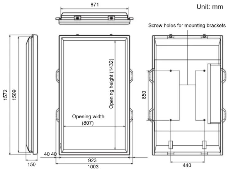
When mounting the monitor, read the manual of the brackets or stand for their mounting procedure. The screw holes for mounting brackets (M10 x 4 holes) are provided on the rear of the monitor.
Note that screw hole depth of the monitor is 30 mm. Loose holding may cause the product to fall, resulting in serious personal injuries as well as damage to the product. The screw and hole should come together with over 20 mm length of thread. Use the bracket which can endure at least 4 times or more the weight of the monitor.
■Compatible signal timing (PC)
| Screen resolution Hsync Vsync Dot frequency | Analogue signal | Digital signal | ||||
| VESA | 640 x 480 | 31.5 kHz | 60 Hz | 25.175 MHz | Yes | Yes |
| 37.9 kHz | 72 Hz | 31.5 MHz | Yes | Yes | ||
| 37.5 kHz | 75 Hz | 31.5 MHz | Yes | Yes | ||
| 800 x 600 | 35.1 kHz | 56 Hz | 36.0 MHz | Yes | - | |
| 37.9 kHz | 60 Hz | 40.0 MHz | Yes | Yes | ||
| 48.1 kHz | 72 Hz | 50.0 MHz | Yes | Yes | ||
| 46.9 kHz | 75 Hz | 49.5 MHz | Yes | Yes | ||
| 848 x 480 | 31.0 kHz | 60 Hz | 33.75 MHz | Yes | Yes | |
| 1024 x 768 | 48.4 kHz | 60 Hz | 65.0 MHz | Yes | Yes | |
| 56.5 kHz | 70 Hz | 75.0 MHz | Yes | Yes | ||
| 60.0 kHz | 75 Hz | 78.75 MHz | Yes | Yes | ||
| 1152 x 864 | 67.5 kHz | 75 Hz | 108.0 MHz | Yes | Yes | |
| 1280 x 768 | 47.8 kHz | 60 Hz | 79.5 MHz | Yes | Yes | |
| 60.3 kHz | 75 Hz | 102.25 MHz | Yes | Yes | ||
| 1280 x 960 | 60.0 kHz | 60 Hz | 108.0 MHz | Yes | Yes | |
| 1280 x 1024 | 64.0 kHz | 60 Hz | 108.0 MHz | Yes | Yes | |
| 80.0 kHz | 75 Hz | 135.0 MHz | Yes | Yes | ||
| 1360 x 768 | 47.7 kHz | 60 Hz | 85.5 MHz | Yes | Yes | |
| 1600 × 1200^*1 | 75.0 kHz | 60 Hz | 162.0 MHz | Yes | Yes | |
| Wide | 1280 x 720 | 44.7 kHz | 60 Hz | 74.4 MHz | Yes | Yes |
| 1920 x 1080 | 66.3 kHz | 60 Hz | 148.5 MHz | Yes | Yes | |
| US TEXT | 720 x 400 | 31.5 kHz | 70 Hz | 28.3 MHz | Yes | Yes |
| Sun | 1024 x 768 | 48.3 kHz | 60 Hz | 64.13 MHz | Yes | - |
| 53.6 kHz | 66 Hz | 70.4 MHz | Yes | - | ||
| 56.6 kHz | 70 Hz | 74.25 MHz | Yes | - | ||
| 1152 x 900 | 61.8 kHz | 66 Hz | 94.88 MHz | Yes | - | |
| 71.8 kHz | 76.2 Hz | 108.23 MHz | Yes | - | ||
| 1280 x 1024 | 71.7 kHz | 67.2 Hz | 117.01 MHz | Yes | - | |
| 81.1 kHz | 76 Hz | 134.99 MHz | Yes | - | ||
| 1600 x 1000 | 68.6 kHz | 66 Hz | 135.76 MHz | Yes | - | |
*1 Displays a reduced image.
* All are compliant only with non-interlaced.
* Depending on the connected PC, images may not be displayed properly even if the compatible signal described above is input.
* The frequency values for the Sun are reference values. A separate conversion adapter (commercially available) may be required for connecting the monitor to the Sun.
■Power management
This monitor conforms to VESA DPMS and DVI DMPM. Both your video card and computer must support the same standard in order for the monitor's power management function to work.
DPMS: Display Power Management Signaling DMPM: Digital Monitor Power Management
| DPMS | Screen | Power consumption | Hsync | Vsync |
| ON STATE | Display | 560 W | Yes | Yes |
| STANDBY | No display | 10 W | No | Yes |
| SUSPEND | Yes | No | ||
| OFF STATE | No | No |
| DMPM | Screen | Power consumption |
| Monitor ON | Display | 560 W |
| Active OFF | No display | 10 W |
■DDC (plug and play)
The monitor supports the VESA DDC (Display Data Channel) standard.
DDC is a signal standard for plug and play between monitors and computers. Information about resolution and other parameters is exchanged between the two. This function can be used if the computer supports DDC and it has been configured to detect plug-and-play monitors.
There are several types of DDC, depending on the communication method used. This monitor supports DDC2B.
■PC1/AV1 input terminal pins
(DVI-D24 pin)
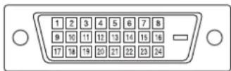
| No. | Function | No. | Function |
| 1 | TMDS data 2- | 13 | N.C. |
| 2 | TMDS data 2+ | 14 | +5 V |
| 3 | TMDS data 2/4 shield | 15 | GND |
| 4 | N.C. | 16 | Hot-plug detection |
| 5 | N.C. | 17 | TMDS data 0- |
| 6 | DDC clock | 18 | TMDS data 0+ |
| 7 | DDC data | 19 | TMDS data 0/5 shield |
| 8 | N.C. | 20 | N.C. |
| 9 | TMDS data 1- | 21 | N.C. |
| 10 | TMDS data 1+ | 22 | TMDS clock shield |
| 11 | TMDS data 1/3 shield | 23 | TMDS clock+ |
| 12 | N.C. | 24 | TMDS clock- |
■RS-232C input terminal pins
(D-sub 9 pin)
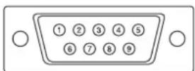
| No. | Function | No. | Function |
| 1 | N.C. | 6 | N.C. |
| 2 | Transmitted data | 7 | N.C. |
| 3 | Received data | 8 | N.C. |
| 4 | N.C. | 9 | N.C. |
| 5 | GND | ||
■RS-232C output terminal pins
(D-sub 9 pin)
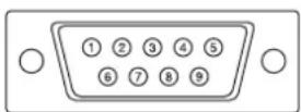
| No. | Function | No. | Function |
| 1 | N.C. | 6 | N.C. |
| 2 | Received data | 7 | N.C. |
| 3 | Transmitted data | 8 | N.C. |
| 4 | N.C. | 9 | N.C. |
| 5 | GND | ||
■PC2 input terminal pins
(Mini D-sub 15 pin)
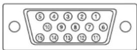
| No. | Function | No. | Function |
| 1 | Red video signal input | 9 | +5 V |
| 2 | Green video signal input | 10 | GND |
| 3 | Blue video signal input | 11 | N.C. |
| 4 | N.C. | 12 | DDC data |
| 5 | GND | 13 | Hsync signal input |
| 6 | GND for red video signal | 14 | Vsync signal input |
| 7 | GND for green video signal | 15 | DDC clock |
| 8 | GND for blue video signal | ||
■PC/AV output terminal pins
(DVI-D24 pin)
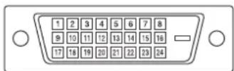
| No. | Function | No. | Function |
| 1 | TMDS data 2- | 13 | N.C. |
| 2 | TMDS data 2+ | 14 | +5 V |
| 3 | TMDS data 2/4 shield | 15 | GND |
| 4 | N.C. | 16 | Hot-plug detection |
| 5 | N.C. | 17 | TMDS data 0- |
| 6 | DDC clock | 18 | TMDS data 0+ |
| 7 | DDC data | 19 | TMDS data 0/5 shield |
| 8 | N.C. | 20 | N.C. |
| 9 | TMDS data 1- | 21 | N.C. |
| 10 | TMDS data 1+ | 22 | TMDS clock shield |
| 11 | TMDS data 1/3 shield | 23 | TMDS clock+ |
| 12 | N.C. | 24 | TMDS clock- |
MEMO
PN-G655RE
LCD FARBMONITOR
DEUTSCH
WICHTIGE INFORMATIONEN
ACHTUNG: HALTEN SIE DAS GERÄT VON REGEN UND JEGLICHER ART VON FEUCHTIGKEIT FERN, UM DIE GEFAHR VON BRAND ODER STROMSCHLAG ZU VERRINGERN.

VORSICHT
natural_image
Two diagrams showing a mechanical component with arrows indicating direction, no text or symbols presentnatural_image
Line drawing of a device casing with internal components and a handle (no text or symbols)natural_image
Technical diagram of a mechanical component with mounting holes and a curved handle (no text or symbols)natural_image
Diagram of a mechanical or electrical component with two vertical supports and upward arrows indicating direction (no text or symbols)natural_image
Technical illustration of a mechanical clamp assembly mounted on a wall, with no visible text or symbols.■Kommunikationsintervall
DPMS: Display Power Management Signaling DMPM: Digital Monitor Power Management
■DDC (Plug and Play)
natural_image
Blank rectangular frame with no text, numbers, or symbols inside the frame (no content)□ Télécommande : 1

natural_image
Two diagrams showing mechanical components with arrows indicating motion, no text or symbols presentnatural_image
Line drawing of a device casing with internal components (no text or symbols)natural_image
Diagram of a mechanical or electrical component with two vertical supports and an upward arrow indicating direction (no text or symbols)natural_image
Technical diagram of a mechanical assembly with mounting holes and a bracket (no text or symbols)natural_image
Diagram of a door handle assembly with mounting holes and dashed lines indicating alignment (no text or labels)Conditions de communication
■DDC (plug and play)
natural_image
Blank rectangular frame with no text, numbers, or symbols inside the frame (no content)natural_image
Two diagrams showing a mechanical component with arrows indicating direction, no text or symbols presentnatural_image
Line drawing of a handheld electronic device casing with a lid and internal components (no text or symbols)natural_image
Diagram of a mechanical or electrical component with two upward arrows indicating direction (no text or symbols present)natural_image
Technical diagram showing a mechanical assembly with mounting holes and a bracket, mounted on a wall (no text or symbols present)natural_image
Diagram of a door handle assembly with mounting holes and dashed lines indicating alignment (no text or labels)DPMS: Display Power Management Signaling DMPM: Digital Monitor Power Management
■DDC (plug and play)
natural_image
Blank white rectangular frame with black border, no text or symbols present□ 遥控器:1

□ 支架孔保护罩: 2
natural_image
Two diagrams showing mechanical components with arrows indicating motion, no text or symbols presentnatural_image
Line drawing of a device casing with internal components (no text or symbols)natural_image
Diagram of a mechanical or electrical component with two upward arrows indicating direction (no text or symbols present)natural_image
Technical illustration of a mechanical clamp assembly mounted on a wall, with no visible text or symbols.natural_image
Technical diagram of a mechanical component with mounting holes and a curved handle (no text or symbols)按下或来调节音量。
按下或来调节亮度。
| STD(标准)→VIVID(鲜明)→sRGB→STD(标准)... |
- sRGB 仅适用于 PC 输入。
■ SCREEN (PC2/PC3) [ 屏幕 (PC2/PC3)]
AUTO(自动)
AUTO (PC2/PC3) [ 自动 (PC2/PC3)]
ID No. SET (ID 号码设置)
480 LINES (PC2/PC3) [480 线 (PC2/PC3)]
768 LINES (PC2/PC3) [768 线 (PC2/PC3)]
- 选择并设置您想要的项目。
ALL RESET(全部重置)
把设定重设为出厂设置。
IDCK0000 ← (无意义的参数。)
Printed on recycled paper.