
G728II - Laptop Nexoc - Free user manual and instructions
Find the device manual for free G728II Nexoc in PDF.
| Product Type | Laptop |
| Brand | Nexoc |
| Model | G728II |
| Processor | Intel Core i7 (up to i7-4900MQ 2.80 GHz) |
| Chipset | Intel HM87 |
| RAM Memory | Up to 24 GB DDR3L 1600 MHz (3 SODIMM slots) |
| Storage | 2.5" SATA HDD/SSD (RAID 0/1), optical drive (Super Multi or Blu-ray), mSATA SSD (optional) |
| Display | Model A: 15.6" HD+/FHD; Model B: 17.3" HD+/FHD |
| Graphics | Intel HD Graphics 4600 + NVIDIA GeForce GTX 765M 2 GB GDDR5 (Optimus technology) |
| Audio | Sound Blaster Cinema, 2 speakers, built-in microphone |
| Network Connectivity | Gigabit Ethernet, Wi-Fi 802.11a/g/n, Bluetooth 4.0 (optional), 3G (Model A) |
| Ports | 1 USB 2.0, 3 USB 3.0, 1 eSATA/USB combo, HDMI, VGA, headphone out, microphone in, S/PDIF, RJ-45, DC jack |
| Keyboard | Full-size with numeric keypad and function keys |
| Touchpad | Integrated with scrolling function |
| Card Reader | Multi-in-1 (MMC, RS MMC, SD, Mini SD, SDHC, SDXC) |
| Security | BIOS password, Kensington lock, fingerprint reader (Model A option) |
| Battery | Lithium-Ion 8-cell, 76.96 Wh (smart) |
| Power Adapter | Input 100-240 V AC, output 19 V DC, 6.15 A (120 W) |
| Dimensions (Model A) | 374 x 250 x 16.3-42.7 mm |
| Dimensions (Model B) | 413 x 277.5 x 17.5-44 mm |
| Weight (Model A) | 2.7 kg (with battery and optical drive) |
| Weight (Model B) | 3.2 kg (with battery and optical drive) |
| Operating Temperature | 5 °C to 35 °C |
| Operating Humidity | 20 % to 80 % RH |
| Care and Cleaning | Use a soft, dry cloth. Do not use volatile or abrasive products. Disconnect and remove battery before cleaning. |
| Repairability | Have repairs performed by a qualified technician. Spare parts available from the manufacturer. |
Frequently Asked Questions - G728II Nexoc
User questions about G728II Nexoc
0 question about this device. Answer the ones you know or ask your own.
Ask a new question about this device
Download the instructions for your Laptop in PDF format for free! Find your manual G728II - Nexoc and take your electronic device back in hand. On this page are published all the documents necessary for the use of your device. G728II by Nexoc.
USER MANUAL G728II Nexoc
Introduction (English)
This Concise User's Guide introduces the main features of your computer. The English version of this guide begins on page 1. The expanded User's Manual is on the Device Drivers & Utilities + User's Manual disc.
About this Concise User Guide ....1
System Startup ....3
RAID Setup 5
System Map: Front View with LCD Panel Open (Model A) .....8
System Map: Front View with LCD Panel Open (Model B) .....9
LED Indicators ....10
Hot Key Buttons & Keyboard 11
Control Center 13
System Map: Front, Left, Right & Rear Views (Model A) .....15
System Map: Front, Left, Right & Rear Views (Model B) .....16
System Map: Bottom View 17
Windows Control Panel 18
Windows Start Screen & Desktop 18
Apps & Tiles ....19
Windows 8 Charms Bar 19
Video Features ....20
Audio Features 23
Fingerprint Reader 24
3G Module 25
Driver Installation 26
Troubleshooting 27
Specifications 28
Inhalt
About this Concise User Guide
This quick guide is a brief introduction to getting your system started. This is a supplement, and not a substitute for the expanded English language User's Manual in Adobe Acrobat format on the Device Drivers & Utilities + User's Manual disc supplied with your computer. This disc also contains the drivers and utilities necessary for the proper operation of the computer (Note: The company reserves the right to revise this publication or to change its contents without notice).
Some or all of the computer's features may already have been setup. If they aren't, or you are planning to re-configure (or re-install) portions of the system, refer to the expanded User's Manual. The Device Drivers & Utilities + User's Manual disc does not contain an operating system.
Regulatory and Safety Information
Please pay careful attention to the full regulatory notices and safety information contained in the expanded User's Manual on the Device Drivers & Utilities + User's Manual disc.
© April 2013
Trademarks
Intel and Intel Core are trademarks/registered trademarks of Intel Corporation.
Instructions for Care and Operation
The computer is quite rugged, but it can be damaged. To prevent this, follow these suggestions:
- Don't drop it, or expose it to shock. If the computer falls, the case and the components could be damaged.
- Keep it dry, and don't overheat it. Keep the computer and power supply away from any kind of heating element. This is an electrical appliance. If water or any other liquid gets into it, the computer could be badly damaged.
- Avoid interference. Keep the computer away from high capacity transformers, electric motors, and other strong magnetic fields. These can hinder proper performance and damage your data.
- Follow the proper working procedures for the computer. Shut the computer down properly and don't forget to save your work. Remember to periodically save your data as data may be lost.
Servicing
Do not attempt to service the computer yourself. Doing so may violate your warranty and expose you and the computer to electric shock. Refer all servicing to authorized service personnel. Unplug the computer from the power supply. Then refer servicing to qualified service personnel under any of the following conditions:
- When the power cord or AC/DC adapter is damaged or frayed.
- If the computer has been exposed to any liquids.
- If the computer does not work normally when you follow the operating instructions.
- If the computer has been dropped or damaged (do not touch the poisonous liquid if the LCD panel breaks).
- If there is an unusual odor, heat or smoke coming from your computer.
Safety Information
- Only use an AC/DC adapter approved for use with this computer.
- Use only the power cord and batteries indicated in this manual. Do not dispose of batteries in a fire. They may explode. Check with local codes for possible special disposal instructions.
- Do not continue to use a battery that has been dropped, or that appears damaged (e.g. bent or twisted) in any way. Even if the computer continues
to work with a damaged battery in place, it may cause circuit damage, which may possibly result in fire.
- Make sure that your computer is completely powered off before putting it into a travel bag (or any such container).
- Before cleaning the computer, make sure it is disconnected from any external power supplies, peripherals and cables (including telephone lines). It is advisable to also remove your battery in order to prevent accidentally turning the machine on.
- Use a soft clean cloth to clean the computer, but do not apply cleaner directly to the computer. Do not use volatile (petroleum distillates) or abrasive cleaners on any part of the computer.
- Do not try to repair a battery pack. Refer any battery pack repair or replacement to your service representative or qualified service personnel.
Polymer Battery Precautions
Note the following information which is specific to polymer batteries only, and where applicable, this overrides the general battery precaution information.
- Polymer batteries may experience a slight expansion or swelling, however this is part of the battery's safety mechanism and is not a cause for concern.
- Use proper handling procedures when using polymer batteries. Do not use polymer batteries in high ambient temperature environments, and do not store unused batteries for extended periods.

Battery Disposal & Caution
The product that you have purchased contains a rechargeable battery. The battery is recyclable. At the end of its useful life, under various state and local laws, it may be illegal to dispose of this battery into the municipal waste stream. Check with your local solid waste officials for details in your area for recycling options or proper disposal.
Danger of explosion if battery is incorrectly replaced. Replace only with the same or equivalent type recommended by the manufacturer. Discard used battery according to the manufacturer's instructions.
System Startup
- Remove all packing materials.
- Place the computer on a stable surface.
- Insert the battery and make sure it is locked in position.
- Securely attach any peripherals you want to use with the computer (e.g. keyboard and mouse) to their ports.
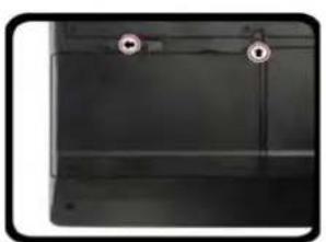
- Attach the AC/DC adapter to the DC-In jack at the rear of the computer, then plug the AC power cord into an outlet, and connect the AC power cord to the AC/DC adapter.
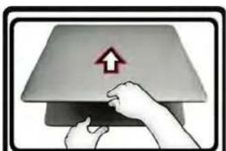
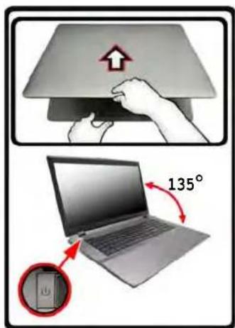
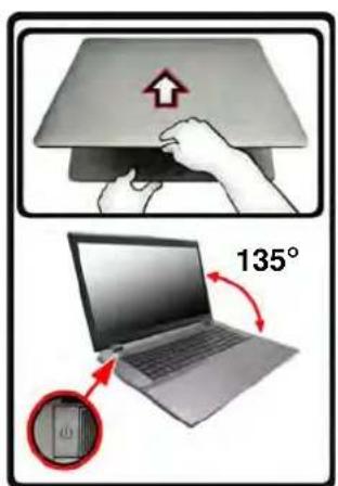
- Use one hand to raise the lid/LCD to a comfortable viewing angle (do not exceed 135 degrees); use the other hand (as illustrated in Figure 1) to support the base of the computer (Note: Never lift the computer by the lid/LCD).
- Press the power button to turn the computer "on".
System Software
Your computer may already come with system software pre-installed. Where this is not the case, or where you are re-configuring your computer for a different system, you will find this manual refers to Microsoft Windows 8.
natural_image
Close-up of a black metal panel with two circular holes and a vertical seam (no text or symbols visible)
natural_image
Illustration of hands pressing a device with an upward arrow symbol (no text or labels)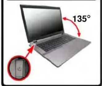

Shut Down
Note that you should always shut your computer down by clicking Settings in the Charms Bar (use the Windows Logo Key C key combination to access the Charms Bar) and choosing Shut down from the Power menu.
This will help prevent hard disk or system problems.
Figure 1 - Opening the Lid/LCD/Computer with AC/DC Adapter Plugged-In
Model Differences
This notebook series includes two different model types that mainly differ as indicated in the table below. Note that your model may appear slightly different from those pictured in this manual.
| Feature Model | A Model B | |
| Display Type | 15.6" (39.62cm) HD+/ FHD 17.3" (43.94cm) HD+/ FHD | |
| 3G module Option | Not Supported | |
| Fingerprint Reader Module | Option Not Supported | |
| Dimensions & Weight | 374mm (w) * 250mm (d) * 16.3 - 42.7mm (h)2.7kg with ODD and Battery | 413mm (w) * 277.5mm (d) * 17.5 - 44mm (h)3.2kg with ODD and Battery |
Table 1 - Model Differences
HDD RAID Support
Your hard disk(s) can be set up in AHCI mode or RAID mode (for increased performance or protection). Note that setting up your hard disk(s) in RAID mode needs to be done prior to installing the Windows OS (see RAID Setup on page 5).
RAID Setup
You may use your hard disks in combination with Striping (RAID 0), Mirroring (RAID 1) or Recovery for either fault tolerance or performance.
| RAID Level Description | |
| RAID 0(at lease two hard disks needed) | Identical drives reading and writing data in parallel to increase performance. RAID 0 implements a striped disk array and the data is broken into blocks and each block is written to a separate disk drive. |
| RAID 1(at lease two hard disks needed) | Identical drives in a mirrored configuration used to protect data. Should a drive that is part of a mirrored array fail, the mirrored drive (which contains identical data) will handle all the data. When a new replacement drive is installed, data to the new drive is rebuilt from the mirrored drive to restore fault tolerance. |
| Recovery(at lease two hard disks needed) | Two Identical drives copying data between a master and a recovery disk. This provides more control over how data is copied between the master and recovery drives, fast volume updates and the ability to view the data in Windows Explorer. |
Table 2 - RAID Description
Prepare the following before setting up your serial ATA hard disks in RAID mode:
- The Microsoft Windows 8 OS disc.
- A hard disk installed in the Primary HDD bay.
- A second (identical) hard disk installed in the Secondary HDD bay.
- The Device Drivers & Utilities + User's Manual disc.
- A USB flash drive.
- An operable computer (to copy files from the Device Drivers & Utilities + User's Manual disc to the USB flash drive).
Note: All hard disks in a RAID should be identical (the same size and brand) in order to prevent unexpected system behavior.
RAID Setup Procedure
Before setting up the system you will need to copy a driver folder (on the Device Drivers & Utilities + User's Manual disc) to a USB flash drive or external USB hard disk. However you will need to go to an operable computer and copy the driver folder to a USB flash drive or external USB hard disk.
- Go to the operable computer and insert a USB flash drive or external USB hard disk.
- Insert the Device Drivers & Utilities + User's Manual disc into the CD/DVD drive of the operable computer.
-
Copy the f6flpy-x64 folder from the location below (D: denotes your DVD drive) on the Device Drivers & Utilities + User's Manual disc to the USB flash drive or external USB hard disk.
-
For Windows 8 32bit = D:\Options\RAID\f6flpy-x86
-
For Windows 8 64bit = D:\Options\RAID\f6flpy-x64
-
Start-up your notebook computer and press
to enter the BIOS. - Go to the Boot menu, select OS Select and press
. - Set OS Select to "Windows 8" and set UEFI Boot to "Enabled".
- Press
to exit the menu and go to the Advanced menu. - Select SATA Mode, press
and select "RAID Mode". - Press
and to "Save Changes and Reset". - After the computer restarts press
to enter the BIOS again. - Go to Intel(R) Rapid Storage Technology (in the Advanced menu) and press
. - Select Create RAID Volume and press
. - You can now setup your RAID volume using any two installed disks.
- Go to Name: and press
. - Type a name of your choice for your RAID volume and press
.
![[300] Name: MyRAID +/- Select Enter, No. +/-. Chan F1. Genes F3. OptLm Id: Sage R5: Print](/content/2026/02/364537/images/a3af3c7b35023a9a73b2732f38f4e37f8fffcb535e77488034fe75dab4f67a3d.jpg)
Figure 2 Name the RAID Volume (Ad- vanced > Intel(R) Rapid Storage Technology)
- Go to RAID Level: and press
. - Choose the RAID Level required (see Table 2 on page 5) and press
.
• RAID0 (Stripe)/RAID1 (Mirror)/Recovery
- Go to any of the disks listed under Select Disks: and select a disk name and press
. - Move the cursor down (use the arrow keys) onto X (o select the disk required) and press
.
If you have selected a Recovery level RAID then you need to select one disk to be Master disk (M) and one disk to be the Recovery disk (R).
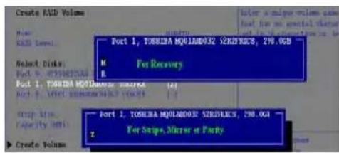
Figure 3 Select Disks
- You should select two identical disks to form your RAID volume.
- If you have selected RAID0 (Stripe) then you can adjust the "Strip Size" to your requirements.
- If you have selected Recovery then you can adjust the Synchronization to "On Request" or "Continuous".
-
Go to Create Volume and press
. -
The RAID volume will then be created and the RAID information will be displayed under Intel(R) Rapid Storage Technology (in the Advanced menu).
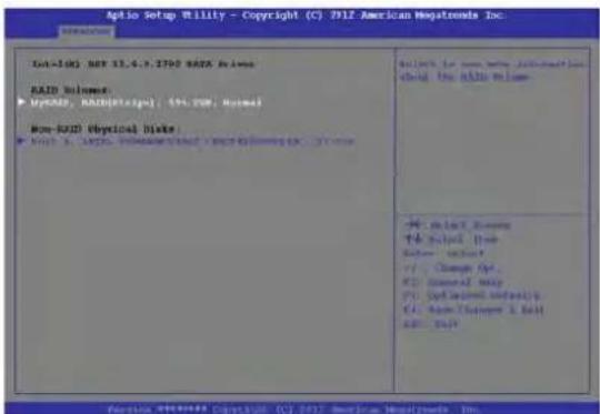
Figure 4 - RAID Information (Advanced > Intel(R) Rapid Storage Technology)
- Press
to exit the menu. - Press
and to "Save Changes and Reset", however ensure that the two conditions in the bulleted points below are met before doing so.
- Make sure the Windows 8 OS DVD is in the DVD drive and as the computer starts up it will automatically boot from the Windows 8 OS DVD (you will be prompted to press a key to boot from the DVD).
- Make sure your USB flash drive or external USB hard disk is attached to one of the USB ports on the computer.
-
Press
as the computer starts up to bring up the boot device menu. -
Select the DVD drive containing the Windows 8 OS DVD and press
. - Press a key at system startup to begin installing Windows from your Microsoft Windows 8 disc.
- Click Next > Install Now to continue installing the operating system as normal (see your Windows documentation if you need help on installing the Windows OS).
- A prompt will appear to ask you to Load Driver.
- Click Browse and browse to the location you copied the files to on your USB flash drive or external USB hard disk (X: denotes your USB flash drive or external USB hard disk):
• X:\f6flpy-x86 (for Windows 8 32bit)
• X:\f6flpy-x64 (for Windows 8 64bit)
-
Click Next.
-
Follow the on-screen instructions to install the Windows 8 operating system.
- Install the Windows drivers. Make sure you install the Intel Rapid Storage Technology (IRST) driver.
System Map: Front View with LCD Panel Open (Model A)
Figure 5
Front View with LCD Panel Open (Model A)
- PC Camera (Optional)
- *PC Camera LED *When the PC camera is in use, the LED will be illuminated in red.
- LCD
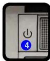
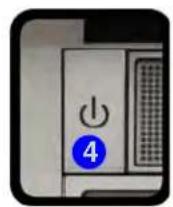
- Power Button
- LED Indicators
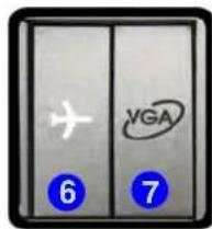
- Airplane Mode Button
- GPU Button
- Speakers
- Keyboard
- Microphone
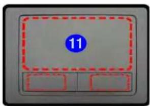
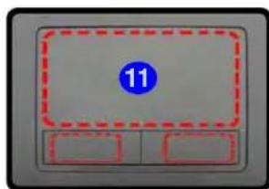
- Touchpad & Buttons
- Fingerprint Reader (Optional for Model A Only)
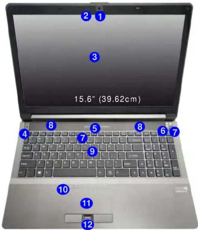
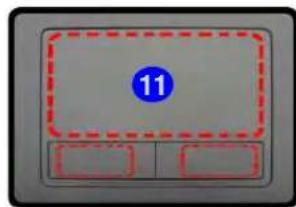
Note that the Touchpad and Buttons valid operational area is that indicated within the red dotted lines above.
System Map: Front View with LCD Panel Open (Model B)
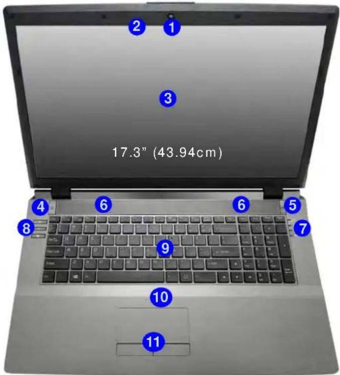
Figure 6 Front View with LCD Panel Open (Model B)
- PC Camera (Optional)
- *PC Camera LED *When the PC camera is in use, the LED will be illuminated in red.
- LCD
- Power Button
- GPU Button
- Speakers
- LED Indicators
- Hot Key Buttons
- Keyboard
- Microphone
- Touchpad & Buttons
Note that the Touchpad and Buttons valid operational area is that indicated within the red dotted lines above.
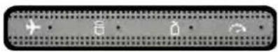
LED Indicators
The LED indicators on the computer display helpful information about the current status of the computer.

| Icon Color Description | ||
 | ||
| Orange | The AC/DC Adapter is Plugged In | |
| Green The Computer is On | ||
| Blinking Green The Computer is in Sleep Mode | ||
| Orange The Battery is Charging | ||
| Green The Battery is Fully Charged | ||
| Blinking Orange | The Battery Has Reached Critically Low Power Status | |
| Green Number Lock Activated | ||
| Green Caps Lock Activated | ||
| Green Scroll Lock Activated | ||
| Orange | The AC/DC Adapter is Plugged In | |
| Green The Computer is On | ||
| Blinking Green The Computer is in Sleep Mode | ||
| Orange The Battery is Charging | ||
| Green The Battery is Fully Charged | ||
| Blinking Orange | The Battery Has Reached Critically Low Power Status | |
| Green Number | Lock Activated | |
| Green Caps | Lock Activated | |
| Green Scroll | Lock Activated | |
| U | Orange | The AC/DC Adapter is Plugged In |
| Green The Computer is On | ||
| Blinking Green The Computer is in Sleep Mode | ||
| I | Orange The Battery is Charging | |
| Green The Battery is Fully Charged | ||
| Blinking Orange | The Battery Has Reached Critically Low Power Status | |
| Green Number | Lock Activated | |
| Green Caps | Lock Activated | |
| Green Scroll | Lock Activated | |
Table 3 - Front Left LED Indicators
| Icon Color Description | ||
  Model A Model A  Model B Model B | ||
 | Green UMA Mode Activated | |
| Orange Optimus Mode Activated | ||
 | Orange | NVIDIA Discrete GPU (dGPU) Activated |
 | Green | Intel Integrated GPU (iGPU) Activated |
 | White | The Hard Disk/Optical Device is in use |
 | Green | Airplane Mode is ON (the WLAN & Bluetooth Modules are OFF) |
 | White | The Computer is On |
Table 4 - Top Case LED Indicators
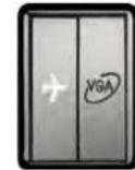
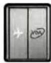
Hot Key Buttons & Keyboard
Press the Hot Key buttons on the computer to toggle the appropriate function on/off.
| Icon Description | ||
 |  | Turn On/Off Airplane Mode |
Table 5 - Hot Key Button (Model A)
| Icon Description | ||
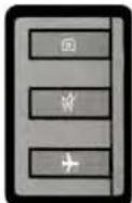 | [ZGDB] | PC Camera Power Toggle |
 | Mute Toggle | |
 | Turn On/Off Airplane Mode | |
Table 6 - Hot Key Buttons (Model B)
The keyboard has a numeric keypad for easy numeric data input. Pressing NumLk turns on/off the numeric keypad. It also features function keys to allow you to change operational features instantly.
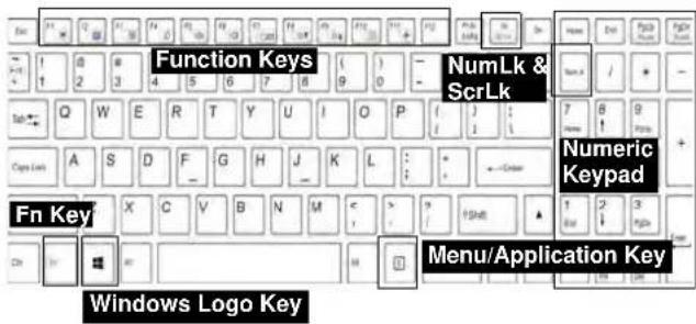

Windows Logo Keyboard Shortcut
Use the Windows Logo Key + D key combination to switch between the Start screen and Windows Desktop.
Menu/Application Keyboard Shortcut
When the Desktop app is running you can use the Menu/Application key ☑ in the keyboard to display the context menu as per a mouse right-click.
Figure 7 - Keyboard
Function Keys
The function keys (F1 - F11 etc.) will act as hot keys when pressed while the Fn key is held down. In addition to the basic function key combinations, some visual indicators are available (in the Windows Desktop application only and not in the Start Screen) when the hot key driver is installed.
| Keys | Function/Visual Indicators | Keys | Function/Visual Indicators | ||
| Fn + ~ Play/Pause (in Audio/Video Programs) Fn + F8/F9 | Brightness Decrease/ Increase | ||||
| Fn + F1 Touchpad Toggle |   | Fn + F10 | PC Camera Power Toggle |   | |
| Fn + F2 | Turn LCD Backlight Off(Press a key to or use TouchPad to turn on) | Fn + F11(→) | Airplane Mode Toggle | ||
| Fn + F3(HYW) | Mute Toggle Num Lk Number | (GEICB) Icued | [CBC4] [WBB2] | ||
| Fn + F4 Sleep Toggle Fn + ScrLk Scroll Lock Toggle | [20WC]  | ||||
| Fn + F5/F6 | Volume Decrease/ Increase | Caps Lock Caps Lock Toggle |  [S64Z] [S64Z] | ||
| Fn + F7 | Change Display Configuration (see page 22) | Fn + Esc | Control Center Toggle (see page 13) | ||
Table 7 - Function Keys & Visual Indicators
Control Center
When in the Windows Desktop application ( not in the Start Screen), press the Fn + Esc key combination, or double-click the icon [icon] in the notification area of the taskbar to toggle the Control Center on/off. The Control Center gives quick access to frequently used controls, and enables you to quickly turn modules on/off.
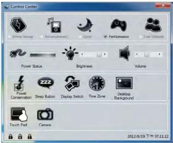
Figure 8 - Control Center
Click on any button to turn any of the modules (e.g. TouchPad, Camera) on/off. Click on Power Conservation to switch between Performance, Balanced or Energy Star modes. Click on the buttons (or just click and hold the mouse button) to adjust the slider for Brightness/Volume. Click on Display Switch/Time Zone/Desktop Background to bring up the appropriate Windows control panel. Click on the Sleep button to put the computer into Hibernate or Sleep modes.
Power Status


The Power Status icon will show whether you are currently powered by the battery, or by the AC/DC adapter plugged in to a working power outlet. The power status bar will show the current battery charge state.
Brightness

The Brightness icon will show the current screen brightness level. You can use the slider to adjust the screen brightness or the Fn + F8/F9 key combinations, or use the Fn + F2 key combination to turn off the LED backlight (press any key to turn it on again). Note that screen brightness is also effected by the Power Mode selected.
Volume

The Volume icon will show the current volume level. You can use the slider to adjust the volume or the Fn + F5/F6 key combinations, or use the Fn + F3 key combination to mute the volume.
Power Conservation
This system supports Energy Star power management features that place computers (CPU, hard drive, etc.) into a low-power sleep mode after a designated period of inactivity. Click either the Performance, Balanced or Energy Star button.

Sleep

Click the Sleep button to bring up the Hibernate or Sleep Buttons, and click either button to have the computer enter the appropriate power-saving mode.
Display Switch

Click the Display Switch button to access the menu (or use the P key combination) and select the appropriate display mode.
Time Zone

Clicking the Time Zone button will access the Date and Time Windows control panel.
Desktop Background

Clicking the Desktop Background button will allow you to change the desktop background picture.
Touchpad/PC Camera

Click any of these buttons to toggle the Touchpad or module's power status. A crossed out icon will appear over the top left of the icon when it is off . Note that the power status of a module, and Touchpad power, is also effected by the Power Mode selected.
System Map: Front, Left, Right & Rear Views (Model A)
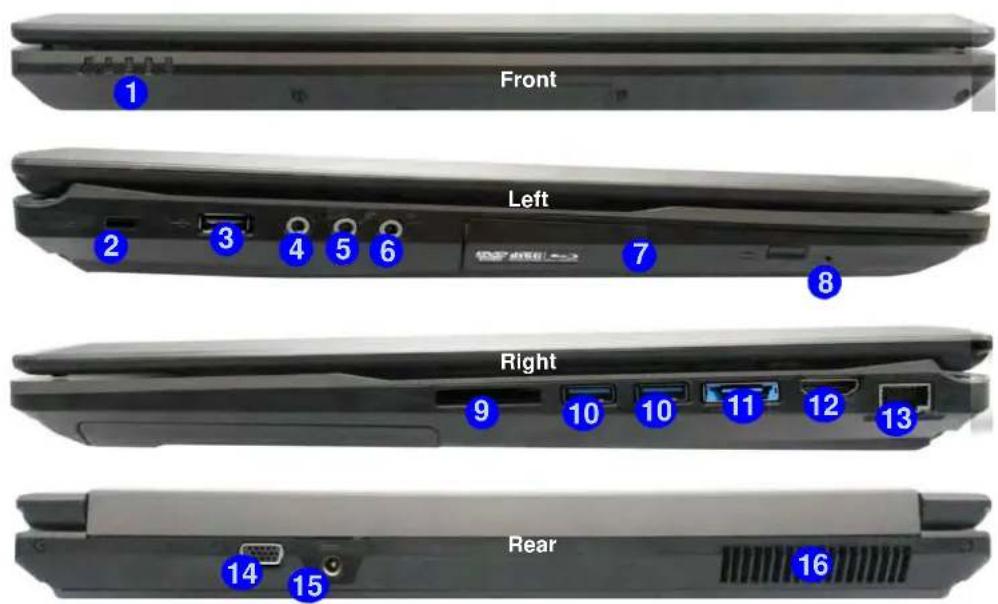
Figure 9 Front, Left, Right & Rear Views (Model A)
- LED Indicators
- Security Lock Slot
- USB 2.0 Port
- S/PDIF-Out Jack
- Microphone-In Jack
- Headphone-Out Jack
- Optical Device Drive Bay
- Emergency Eject Hole
- Multi-in-1 Card Reader
- USB 3.0 Ports
- Combined eSATA/USB 3.0 Port
- HDMI-Out Port
- RJ-45 LAN Jack
- External Monitor Port
- DC-In Jack
- Vent

Disc Emergency Eject
If you need to manually eject a disc (e.g. due to an unexpected power interruption) you may push the end of a straightened paper clip into the emergency eject hole. Do not use a sharpened pencil or similar object that may break and become lodged in the hole.

USB
The USB 3.0 ports 10 are colored blue. USB 3.0 will transfer data much faster than USB 2.0, and is backwards-compatible with USB 2.0.
System Map: Front, Left, Right & Rear Views (Model B)


Figure 10 Front, Left, Right & Rear Views (Model B)
- LED Indicators
- Security Lock Slot
- USB 2.0 Port
- S/PDIF-Out Jack
- Microphone-In Jack
- Headphone-Out Jack
- Optical Device Drive Bay
- Emergency Eject Hole
- Multi-in-1 Card Reader
- USB 3.0 Ports
- Combined eSATA/USB 3.0 Port
- HDMI-Out Port
- RJ-45 LAN Jack
- External Monitor Port
- DC-In Jack
- Vent

Disc Emergency Eject
If you need to manually eject a disc (e.g. due to an unexpected power interruption) you may push the end of a straightened paper clip into the emergency eject hole. Do not use a sharpened pencil or similar object that may break and become lodged in the hole.

USB
The USB 3.0 ports 10 are colored blue. USB 3.0 will transfer data much faster than USB 2.0, and is backwards-compatible with USB 2.0.
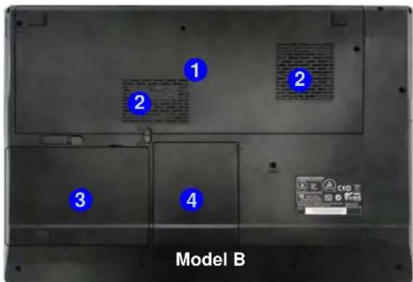
System Map: Bottom View

CPU
The CPU is not a user serviceable part. Accessing the CPU in any way may violate your warranty.
Overheating
To prevent your computer from overheating make sure nothing blocks any vent while the computer is in use.

Battery Information
Always completely discharge, then fully charge, a new battery before using it. Completely discharge and charge the battery at least once every 30 days or after about 20 partial discharges (see the expanded User's Manual on the Device Drivers & Utilities + User's Manual disc).
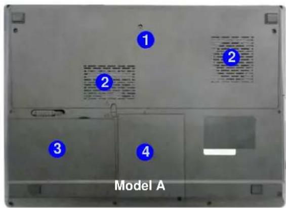
Figure 11
Bottom View
- Component Bay Cover
- Vent
- Battery
- HDD Bay
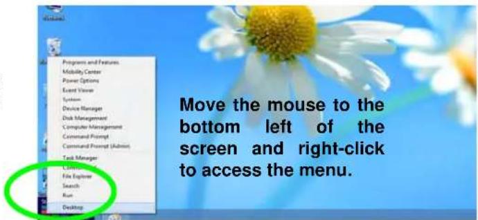
Windows Control Panel
Throughout this manual you will see an instruction to open the Control Panel. In Windows 8 right-click the lower left hot corner to bring up the context menu (or use the Windows Logo Key + X key combination) and select Control Panel.
Figure 12
Context
Menu
Windows Start Screen & Desktop
The Apps, control panels, utilities and programs within Windows 8 are accessed from the Start screen and/or Windows Desktop app. The Desktop (which runs as an app within the Start screen) can be accessed by clicking the Desktop item in the Start screen (or by using the Windows Logo Key + D key combination).
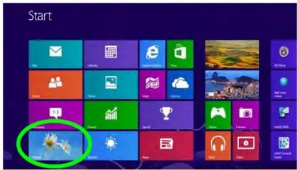
Figure 13 Start Screen
Apps & Tiles
The Windows 8 Start screen will contain a number of apps, and many more will be installed as you add more applications etc. Not all of these apps can fit on one screen so you will often need use the slider at the bottom of the screen in order to view all the necessary Apps.
Windows 8 Charms Bar
The right side of the screen displays the Windows 8 Charms Bar. The Charms Bar contains the Search, Share, Start, Devices and Settings menus. To access up the Charms Bar move the cursor to the upper or lower right corners of the screen, and then hover over one of the items in the Charms Bar to activate it (the bar will be black when it is active), or use the Windows Logo Key C key combination.
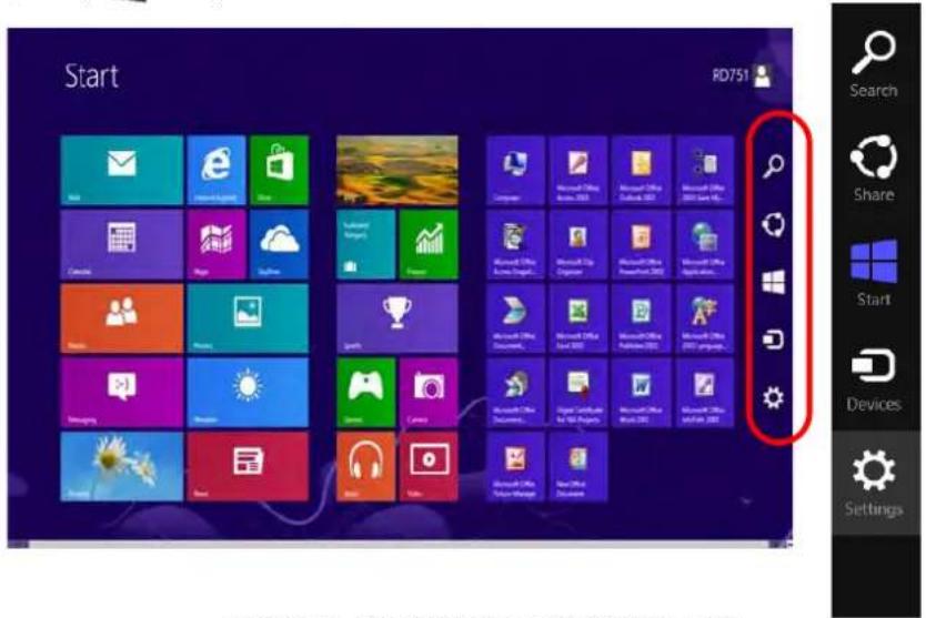
Figure 14 - Start Screen with Charms Bar
Video Features
The system features both an Intel's Integrated GPU (for power-saving) and an NVIDIA's discrete GPU (for performance). You can switch display devices, and configure display options as long as the video drivers are installed.
To access the Display control panel in Windows:
- Go to the Control Panel.
- Click Display (icon) - in the Appearances and Personalization category.
- Click Adjust Screen Resolution/Adjust resolution.
- Right-click the desktop (use the Windows Logo Key 🎨 + D key combination to access the desktop) and select Screen resolution.
- Use the dropbox to select the screen resolution.
- Click Advanced settings.
OR
To access the Intel® Graphics and Media Control Panel:
- Go to the Control Panel.
- Click Intel(R) Graphics and Media in the Icon view.
- Right-click the desktop (use the Windows Logo Key + D key combination to access the desktop) and select Graphics Properties from the menu.
- Choose the application mode (Basic, Advanced or Wizard).
OR
To access the NVIDIA Control Panel:
- Go to the Control Panel.
- Click NVIDIA Control Panel (icon) - in the Appearances and Personalization category.
- Right-click the desktop (use the Windows Logo Key + D key combination to access the desktop) and select NVIDIA Control Panel from the menu.
OR
NVIDIA® Optimus™ Technology
Nvidia® Optimus™ technology is a seamless technology designed to get best performance from the graphics system while allowing longer battery life, without having to manually change settings. Thus when an application is run that requires extra performance or quality, then the system will run the discrete GPU (dGPU); when the system does not require such enhanced performance it will let the integrated (iGPU) handle it.
GPU Button
This computer also features a button what allows the user to switch between Optimus Mode and UMA Mode (Unified Memory Architecture). UMA Mode will use only the integrated GPU; Optimus Mode will allow the system to automatically determine whether the dGPU or iGPU is used. Thus the user can completely control how the graphics system operates. Press the GPU button and the button color will indicate the current mode.
| Icon Color Description | ||
 | Green | UMA Mode ActivatedThe system will use the Intel integrated GPU (iGPU) only |
| Orange | Optimus Mode ActivatedOptimus technology will determine when to use the Intel integrated GPU (iGPU) or NVIDIA discrete GPU (dGPU) automatically | |
Table 8 - GPU Button Modes
The GPU LED indicators will display which GPU is currently in use.
| Icon Color Description | ||
 | Green Intel Integrated GPU (iGPU) Activated | |
 | Orange | NVIDIA Discrete GPU (dGPU) Activated |
Table 9 - GPU LED Indicators
Display Devices
Besides the built-in LCD you can also use an external monitor/flat panel display/TV (TV through HDMI-Out port only), connected to the external monitor port or to the HDMI-Out port (High-Definition Multimedia Interface) as your display device.
Screen Resolution for Metro Style Apps (Windows 8)
The minimum resolution in which Metro style apps will run is 1024x768.
The minimum resolution required to support all the features of Windows 8 (including multitasking with snap) is 1366x768.
Using the Windows Logo Key P Key Combination to Switch Displays
You can also use the +P key combination (or Fn + F7) to quickly change display configuration and modes (this is particularly useful when attaching a projector) in Windows.
- Attach your external display to the external monitor port/HDMI-Out port, and turn it on.
- Press the +P (or Fn + F7) key combination.
- An on-screen menu will pop up.
- Use the cursor keys (☑ + P) to select the appropriate configuration from the menu, and press Enter to confirm the selection.
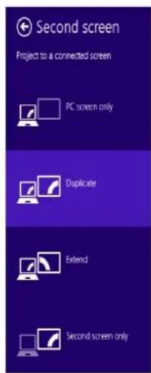
Figure 15 + P (Change Display Configuration)
Audio Features
You can configure the audio options on your computer from the Sound ▶ control panel in Windows, from the HD VDeck icon on the desktop or VIA HD Audio Deck control panel.
The volume may be adjusted by means of the Fn + F5/F6 key combination or the volume icon in the taskbar.
Volume Adjustment
The sound volume level can also be set using the volume control in the Settings menu in the Charms Bar.

Sound Blaster Cinema & HDMI
Note that the Sound Blaster Cinema audio effects do not apply to audio generated through an HDMI connection.
Sound Blaster Cinema EQ
Install the Sound Blaster Cinema application to allow you to configure the audio settings to your requirements for the best performance in games, music and movies.
Sound Blaster Cinema EQ Activation
On the first run of Sound Blaster Cinema EQ you will need to activate the application.
- To activate the application you will need to be connected to the internet.
- Double-click the Activate icon on the desktop/the Start Screen and click the Activate button.
- The program will connect to the internet to verify the activation key.
- Click Finish to complete the application activation.
- Restart the computer after the process is complete.
Sound Blaster Cinema Application
Run the Sound Blaster Cinema control panel from the notification area of the taskbar (or from the item in the Start screen). Click on the tabs to access any of the control panel menus.
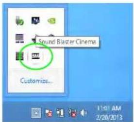
Figure 16 - Sound Blaster Cinema (Taskbar Notification Area Icon)
Fingerprint Reader
(Optional for Model A Only)
Install the driver and enroll your fingerprints as instructed below before use.
Fingerprint Reader Driver Installation
- Click Option Drivers (button).
- Click 4. Install Fingerprint Driver > Yes.
- Click Next.
- Click the button to accept the license and click Next.
- Click Next > Install.
- Click Finish > Yes to restart the computer.
User Enrollment
- Double click the icon (AuthenTec TrueSuite) on the Start Screen.
- Click Yes when you have identified your fingerprint sensor.
- Click Yes when you are ready to enroll your fingerprints.
- Click on the fingerprint diagram to select any finger to enroll.
- You will be required to enter your Windows password (you will be prompted to create a password if you have not already done so) at this point (click OK to confirm the password entry).
- Swipe the finger until the progress bar reaches 100% to enroll that finger.
- You will be prompted to select another finger for enrollment (it is recommended that you enroll a number of fingers).
- Click the button to continue once you have enrolled a number of fingerprints.
-
Enter the required information and click the button to register your software, or click to register later.
-
Your fingerprints will now be enrolled (you may enroll any additional fingerprints at any time).

Settings
Click the Settings 📄 button on the menu bar to access the personalization settings for AuthenTec TrueSuite. Here you can choose to enable/disable Website Log On, Quick-Launch, Fast User Switching and the desktop icon. You can also select the Theme and export/import identities. Click the Save button to save any changes made.
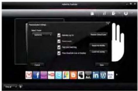
Figure 17 AuthenTec TrueSuite - Settings
3G Module
(Optional for Model A Only)
If you have included an optional 3G module in your purchase option, follow the instructions below to install the USIM card (which will be provided by your service provider), and then run the appropriate application supplied with your module.
USIM Card Insertion
- Turn off the computer, and turn it over and remove the battery ①.
- Insert the USIM card as illustrated below until it clicks into position, and replace the battery.
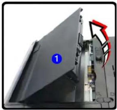
natural_image
Close-up of a black electronic device with a blue circular marker labeled '1' and a red arrowhead, showing internal components (no readable text or symbols)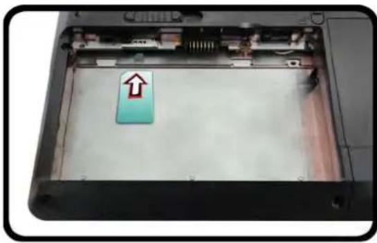
natural_image
Interior view of a computer with an open panel showing a blue square labeled 'Up' and a red upward arrow on the screen (no readable text or symbols)
Figure 18 - Remove the battery and Insert the USIM Card

Driver Installation General Guidelines
As a general guide follow the default on-screen instructions for each driver (e.g. Next > Next > Finish) unless you are an advanced user. In many cases a restart is required to install the driver.
Make sure any modules (e.g. PC Camera or WLAN) are ON before installing the appropriate driver.
Windows Update
After installing all the drivers make sure you enable Windows Update in order to get all the latest security updates etc. (all updates will include the latest hotfixes from Microsoft).
Driver Installation
The Device Drivers & Utilities + User's Manual disc contains the drivers and utilities necessary for the proper operation of the computer. This setup will probably have already been done for you. If this is not the case, insert the disc and click Install Drivers (button), or Option Drivers (button) to access the Optional driver menu. Install the drivers in the order indicated in Figure 19. Click to select the drivers you wish to install (you should note down the drivers as you install them). Note: If you need to reinstall any driver, you should uninstall the driver first.
Manual Driver Installation
Click the Browse CD/DVD button in the Drivers Installer application and browse to the executable file in the appropriate driver folder.
If a Found New Hardware wizard appears during the installation procedure, click Cancel, and follow the installation procedure as directed.
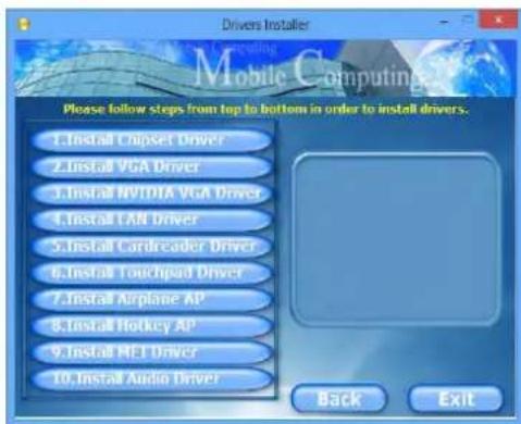
Figure 19 - Install Drivers

Driver Installation & Power
When installing drivers make sure your computer is powered by the AC/DC adapter connected to a working power source. Some drivers draw a significant amount of power during the installation procedure, and if the remaining battery capacity is not adequate this may cause the system to shut down and cause system problems (note that there is no safety issue involved here, and the battery will be rechargeable within 1 minute).
Troubleshooting
| Problem Possible Cause - Solution | |
| The Wireless LAN/Bluetooth modules cannot be detected. | The modules are off as the computer is in Airplane Mode. Check the LED indicator ➗ and/or function key indicator to see if it is in Airplane Mode (see Table 4 on page 10). Use the Fn + F11 key combination or the Airplane Mode button ➗ to toggle Airplane Mode on/off (see Table 7 on page 12). |
| The PC Camera module cannot be detected. | The module is off. Press the Fn + F10 key combination in order to enable the module (see Table 7 on page 12). Run the camera application to view the camera picture. |
| The captured video files from the PC Camera are taking up too much disk space. | Note that capturing high resolution video files requires a substantial amount of disk space for each file.Note that the Windows system requires a minimum of 16GB (32bit) or 20GB (64bit) of free space on the C: drive system partition. It is recommended that you save the capture video file to a location other than the C:drive, limit the file size of the captured video or reduce video resolution. |

Specifications

Latest Specification Information
The specifications listed in this section are correct at the time of going to press. Certain items (particularly processor types/speeds) may be changed, delayed or updated due to the manufacturer's release schedule. Check with your service center for details.
Processor Options
Intel® Core™ i7 Processor
i7-4900MQ (2.80GHz)
8MB L3 Cache, 22nm, DDR3L-1600MHz, TDP 47W
i7-4800MQ (2.70GHz), i7-4700MQ (2.40GHz)
6MB L3 Cache, 22nm, DDR3L-1600MHz, TDP 47W
Core Logic
Intel® HM87 Chipset
BIOS
One 48Mb SPI Flash ROM AMI BIOS
LCD
Model A:
15.6" (39.62cm) HD+/ FHD
Model B:
17.3" (43.94cm) HD+/ FHD
Video Adapter
Intel® Integrated GPU and NVIDIA® Discrete GPU
Supports NVIDIA® Optimus Technology
Intel Integrated GPU (GPU is Dependent on Processor)
Intel® HD Graphics 4600
Dynamic Frequency (Intel Dynamic Video Memory Technology for up to 1.7GB) Microsoft DirectX®11 Compatible
NVIDIA Discrete GPU
NVIDIA® GeForce GTX 765M
2GB GDDR5 Video RAM
Microsoft DirectX®11.1 Compatible
Security
BIOS Password
Security (Kensington® Type) Lock Slot
(Factory Option) Fingerprint Reader (Model A Only)
Audio
High Definition Audio Compliant Interface Sound Blaster™ Cinema 2 * Built-In Speakers Built-In Microphone
Memory
Three 204 Pin SO-DIMM Sockets Supporting DDR3L 1600MHz Memory Memory Expandable up to 24GB
(The real memory operating frequency depends on the FSB of the processor.)
Note: Three SO-DIMMs are only supported by Quad-Core CPUs; Dual-Core CPUs support two SO-DIMMs maximum
Storage
(Factory Option) One Changeable 12.7mm(h) Optical Device Type Drive (Super Multi Drive Module or Blu-Ray Combo Drive Module)
(Factory Option) Two Changeable 2.5" (6cm) 9.5mm (h) SATA (Serial) Hard Disk Drives/Solid State Drives (SSD) supporting RAID level 0/1
(Factory Option) One mSATA Solid State Drive (SSD)
Interface
One USB 2.0 Port
Three USB 3.0 Ports
One eSATA Port (USB 3.0 Port Combined)
One HDMI-Out Port
One Headphone-Out Jack
One Microphone-In Jack
One S/PDIF Out Jack
One RJ-45 LAN Jack
One External Monitor Port
One DC-in Jack
Keyboard
Full-size "WinKey" keyboard (with numeric keypad)
Pointing Device
Built-in Touchpad (scrolling key functionality integrated
Card Reader
Embedded Multi-in-1 Push-Push Card Reader
MMC (MultiMedia Card) / RS MMC
SD (Secure Digital) / Mini SD / SDHC/SDXC
MS (Memory Stick) / MS Pro / MS Duo
Communication
Built-In Gigabit Ethernet LAN
(Factory Option) 2M HD PC Camera Module
(Factory Option) 3G Mini-Card Module (Model A Only)
WLAN/ Bluetooth Half Mini-Card Modules:
(Factory Option) Intel® Centrino® Advanced-N 6235 Wireless LAN (802.11a/g/n) + Bluetooth 4.0
(Factory Option) Intel® Centrino® Wireless-N 2230 Wireless LAN (802.11b/g/n)+ Bluetooth 4.0
(Factory Option) Third-Party Wireless LAN (802.11b/g/n)
(Factory Option) Third-Party Wireless LAN (802.11b/g/n) + Bluetooth 4.0
Mini Card Slots
Model A:
Slot 1 for WLAN Module or WLAN and Bluetooth Combo Module
(Factory Option) Slot 2 for 3G Module or mSATA SSD
Model B:
Slot 1 for WLAN Module or WLAN and Bluetooth Combo Module
(Factory Option) Slot 2 for mSATA SSD
Environmental Spec
Temperature
Operating: 5°C - 35°C
Non-Operating: -20°C - 60°C
Relative Humidity
Operating: 20% - 80%
Non-Operating: 10% - 90%
Power
Full Range AC/DC Adapter
AC Input: 100 - 240V, 50 - 60Hz
DC Output: 19V, 6.15A (120W)
8 Cell Smart Lithium-Ion Battery Pack, 76.96WH
Dimensions & Weight
Model A:
2.7kg with ODD & 76.96WH Battery
Model B:
3.2kg with ODD & 76.96WH Battery


Brightness (Helligkeits)

Time Zone (Zeitzone)

Desktop Background (Desktop-Hintergrund)

Sound Blaster Cinema EQ
Abb. 17 AuthenTec TrueSuite - Einstellungen
3G-Modul
natural_image
Close-up of a black electronic device with a blue circular marker labeled '1' and a red arrow pointing to a component (no readable text or symbols)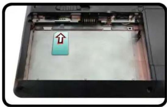
natural_image
Interior view of a computer case with an upward arrow indicator on the screen (no text or symbols visible)
15,6" (39,62cm) HD+/FHD
Modell B:
17,3" (43,94cm) HD+/FHD
Videoadapter
MS (Memory Stick) / MS Pro / MS Duo
Kommunikation
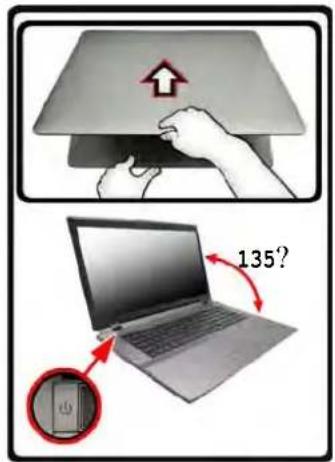

Figure 2 Nommer le volume RAID (Advanced > Intel(R) Rapid Storage Technology)
Figure 3 Select Disks (Sé- lection- ner les disques)
Figure 4 - Informations RAID (Advanced > Intel(R) Rapid Storage Technology)
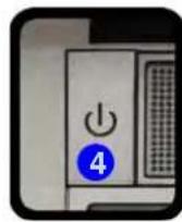
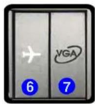
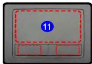
Figure 8 - Control Center
Sleep (Veille)

Sound Blaster Cinema EQ
Application Sound Blaster Cinema
natural_image
Close-up of a black electronic device with a blue circular marker labeled '1' and a red arrow pointing to a component (no readable text or symbols)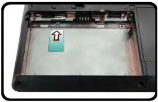
natural_image
Interior view of a computer case showing an open panel with a blue arrow pointing up on the cover (no text or symbols visible)
15,6" (39,62cm) HD+/ FHD
Modèle B:
17,3" (43,94cm) HD+/FHD
Adaptateur vidéo
MS (Memory Stick) / MS Pro / MS Duo
Communication
Apagar
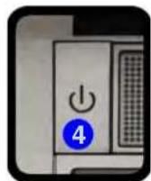

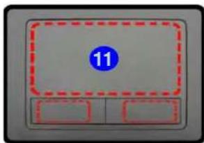
Figura 8 - Control Center
Sound Blaster Cinema EQ
m = 311
Configuración
Figura 17
AuthenTec
TrueSuite -
Configuración
Módulo 3G
natural_image
Close-up of a black electronic device with a blue circular marker labeled '1' and a red arrow pointing to a component (no readable text or symbols)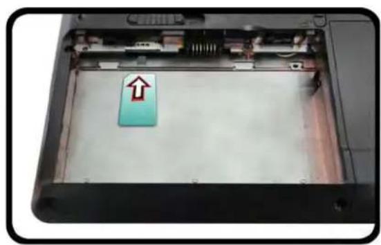
natural_image
Interior view of an open computer case with a highlighted up arrow pointing to a blue rectangular component (no text or symbols visible)
15,6" (39,62cm) HD+/FHD
Modelo B:
17,3" (43,94cm) HD+/FHD
Adaptador de vídeo
GPU integrada de Intel® y GPU discreta NVIDIA®
MS (Memory Stick) / MS Pro / MS Duo
Comunicaciones
LAN Ethernet de 1Gbit incorporada

Spegnimento
Intel(R) Rapid Storage Techno- logy)
Figura 4 - Informazioni RAID (Advanced > Intel(R) Rapid Storage Technology)
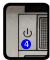
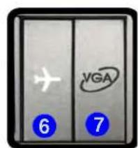
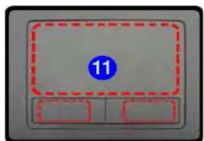
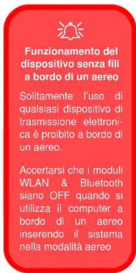
Figura 14 - Schermata Start con la Charms Bar

Sound Blaster Cinema EQ
natural_image
Close-up of a black electronic device with a blue circular label and red arrowhead, showing internal components (no readable text or symbols)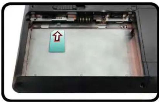
natural_image
Interior view of a computer case showing a blue plastic component with an arrow pointing to it (no text or symbols visible)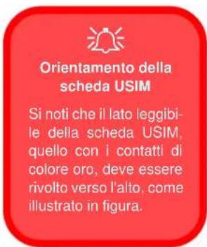

15,6" (39,62cm) HD+/FHD
Modello B:
17,3" (43,94cm) HD+/FHD
Adattatore video
GPU integrata Intel® e GPU discreta NVIDIA®
MS (Memory Stick) / MS Pro / MS Duo
Comunicazione
Gigabit Ethernet LAN integrata
- Introduction (English)
- Inhalt
- About this Concise User Guide
- Regulatory and Safety Information
- Trademarks
- Instructions for Care and Operation
- Servicing
- Safety Information
- Polymer Battery Precautions
- Battery Disposal & Caution
- System Startup
- System Software
- Shut Down
- Model Differences
- HDD RAID Support
- RAID Setup
- RAID Setup Procedure
- System Map: Front View with LCD Panel Open (Model A)
- System Map: Front View with LCD Panel Open (Model B)
- LED Indicators
- Hot Key Buttons & Keyboard
- Windows Logo Keyboard Shortcut
- Menu/Application Keyboard Shortcut
- Function Keys
- Control Center
- Power Status
- Brightness
- Volume
- Power Conservation
- Sleep
- Display Switch
- Time Zone
- Desktop Background
- Touchpad/PC Camera
- Disc Emergency Eject
- USB
- System Map: Bottom View
- CPU
- Overheating
- Battery Information
- Bottom View
- Windows Control Panel
- Windows Start Screen & Desktop
- Apps & Tiles
- Windows 8 Charms Bar
- Video Features
- To access the Display control panel in Windows:
- OR
- To access the Intel® Graphics and Media Control Panel:
- To access the NVIDIA Control Panel:
- NVIDIA® Optimus™ Technology
- GPU Button
- Display Devices
- Screen Resolution for Metro Style Apps (Windows 8)
- Using the Windows Logo Key P Key Combination to Switch Displays
- Audio Features
- Sound Blaster Cinema & HDMI
- Sound Blaster Cinema EQ
- Sound Blaster Cinema EQ Activation
- Sound Blaster Cinema Application
- Fingerprint Reader
- (Optional for Model A Only)
- Fingerprint Reader Driver Installation
- User Enrollment
- Settings
- 3G Module
- USIM Card Insertion
- Driver Installation General Guidelines
- Windows Update
- Driver Installation
- Manual Driver Installation
- Driver Installation & Power
- Specifications
- Latest Specification Information
- Processor Options
- Core Logic
- BIOS
- LCD
- Video Adapter
- Security
- Audio
- Memory
- Storage
- Interface
- Keyboard
- Pointing Device
- Card Reader
- Communication
- WLAN/ Bluetooth Half Mini-Card Modules:
- Mini Card Slots
- Model A:
- Model B:
- Environmental Spec
- Temperature
- Relative Humidity
- Power
- Dimensions & Weight
- Brightness (Helligkeits)
- Time Zone (Zeitzone)
- Desktop Background (Desktop-Hintergrund)
- 3G-Modul
- Kommunikation
- Sleep (Veille)
- Application Sound Blaster Cinema
- Modèle B:
- Adaptateur vidéo
- Configuración
- Módulo 3G
- Adaptador de vídeo
- Comunicaciones
- Spegnimento
- Adattatore video
- Comunicazione
Brand : Nexoc
Model : G728II
Category : Laptop