
AVICZ140BH - GPS Navigation System PIONEER - Free user manual and instructions
Find the device manual for free AVICZ140BH PIONEER in PDF.
| Product Type | GPS Multimedia Navigation System |
| Brand | Pioneer |
| Model | AVIC-Z140BH |
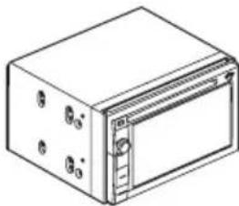
| Dimensions (W x H x D) | 178 mm x 50 mm x 165 mm (approximate, double DIN standard) |
| Weight | Approximately 1.5 kg |
| Power Supply | 12 V DC (vehicle battery, negative ground) |
| Power Consumption | ≤ 10 A (max) |
| Display | Color LCD touchscreen (resolution unspecified, estimated 800x480) |
| Main Functions | GPS navigation, HD radio (built-in tuner), CD/DVD player, Bluetooth, AV inputs, backup camera, voice recognition, traffic information |
| Connectivity | USB, AV mini-jack, RCA inputs, IP-BUS, Bluetooth, rear video output |
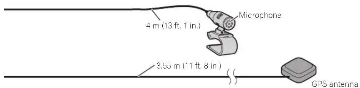
| GPS Antenna | External magnetic GPS antenna, 3 m cable (estimate) |
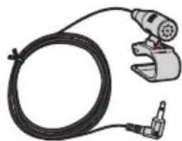
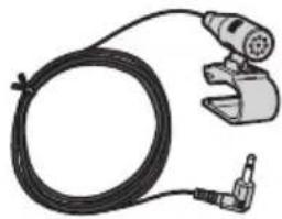
| Microphone | External microphone with sun visor clip, adjustable angle |
| Maintenance and Cleaning | Clean with a soft, dry cloth; do not use chemical products |
| Safety | Do not use while driving (except navigation); installation by a certified professional recommended; comply with local laws |
| Supplied Parts | Navigation unit, power cord, GPS antenna, USB/mini-jack connectors, RCA cables, microphone |
| Repairability | Entrust maintenance to an authorized Pioneer service center; do not attempt self-repair |
| General Information | Installation manual available in French; compatible with optional backup camera |
Frequently Asked Questions - AVICZ140BH PIONEER
User questions about AVICZ140BH PIONEER
0 question about this device. Answer the ones you know or ask your own.
Ask a new question about this device
Download the instructions for your GPS Navigation System in PDF format for free! Find your manual AVICZ140BH - PIONEER and take your electronic device back in hand. On this page are published all the documents necessary for the use of your device. AVICZ140BH by PIONEER.
USER MANUAL AVICZ140BH PIONEER
Precautionsbeforeconnectingthesystem4
Beforeinstallingthisproduct4
Toppreventdamage4
-Noticefortheblue/whitelead5
Partssupplied6
-AVIC-Z140BH6
-AVIC-X940BT6
Connectingthesystem8
Connectingthepowercord(1)10
Connectingthepowercord(2)12
Whenconnectingtoseparatelysoldpower amp14
Whenconnectingarearviewcamera16
Whenconnectingtheexternalvideo component17
-UsinganAVinput(AV1)17
-UsinganAVinput(AV2)18
Whenconnectingthereardisplay18
-Whenusingareardisplayconnectedto rearvideooutput18
Whenconnectingtheexternalunitfeaturing videosource19

Installation
Precautionsbeforeinstallation20
Toavoidelectromagneticinterference20
Beforeinstalling20
-ForAVIC-Z140BHusers21
Installingthenavigationsystem21
thesideofthenavigationunit22
-Fasteningthedetachablefaceplate23
InstallingtheGPSantenna24
-Wheninstallingtheantennainsidethe vehicle(onthedashboardorrear shelf)25
Installingthemicrophone26
-Partssupplied26
-Mountingonthesunvisor26
-Installationonthesteeringcolumn27
-Adjustingthemicrophoneangle27
Yournewnavigation systemandthismanual
- Thenavigationfeaturesofthisproduct (andtherearviewcameraoptionifpurchased)areintendedsolelytoaidyouin theoperationofyourvehicle.Itisnotasubstituteforyourattentiveness,judgment andcarewhendriving.
- Neverusethis navigationsystemtoroute tohospitals,policestations,orsimilarfacilitiesinanemergency.Pleasecalltheappropriateemergencynumber.
- Donotoperatethisnavigationsystem(or therearviewcameraoptionifpurchased)if doing sowilldivertyourattentioniny wayfromthesafeoperationofyourvehicle. Alwaysobservesafedrivingrulesandfollowallexistingtrafficregulations.Ifyouexperienceddifficultyinoperatingthesystem orreadingthedisplay,parkourvehicleinasafelocationandapplytheparkingbrake beforemakingthenecessaryadjustments.
- This manualexplainshowtoinstallthisnavigationsysteminyourvehicle. Operation ofthisnavigationsystemisexplained in these separatemanualsforthenavigation system.
- Donotinstallthisproductwhereitmay(i) obstructthedriver'svision,(ii)impairthe performanceofanyofthevehicle'soperatingsystemsof safetyfeatures,including airbags,hazardlampbuttons,or(iii)impairo thedriver'sabilitytosafelyoperatorethevehic1e.Insomecases,itmaynotbepossible toinstallthisproductbecauseofthevehic1cetypeortheshapeofthevehicleinterior.
Important safeguards 工 WARNING
Pioneerdoesn't recommend that you install your navigationsystemyourself. WerecommendthatonlyauthorizedPioneerservicepersonnel,whohavespecialtrainingandexperienceinmobileelectronics,setupandinstallthisproduct.NEVERSERVICETHISPRODUCTYOURSELF.Installingorservicingsthisproductanditsconnectingcablesmayexposeyoutotheriskofelectricshock orotherhazards,andcausedamagetothenavigationsystemthatisnotcoveredbywarranty.
- Readthismanuallyandcarefullybefore installing your navigationsystem.
- Keepthismanualhandyforfuturereference.
- Paycloseattentiontoall warningsinthis manualandfollowtheinstructionscarefully.
- This navigationsystemmayincertaincircumstancesdisplayinaccuratepositionof yourvehicle,thedistanceofobjectsshown onthescreen,andcompassdirections.In addition,thesystemhascertainlimitations,includingtheinabilitytoidifyone-waystreets,temporarytrafficrestrictions andpotentiallyunsafedrivingsareas.Please exerciseourownjudgmentinthelightof actualdrivingconditions.
- Aswithanyaccessoryinyourvehicle'sinterior,thenavigationsystemshouldnotdivertyourattentionfromthesafeoperationofyourvehicle.Ifyouexperienceddifficultyinoperatingthesystemorreadingthedisplay,pleasemakeadjustmentswhilesafelyparked.
- Pleaseremembertowearyourseatbeltat alltimeswhileoperatingyourvehicle.If youareinanaccident,yourinjuriescanbe considerablymoresevereifyourseatbelt isnotproperlybuckled.
- Certain country and government laws may prohibit or restrict the placement and use of this system in your vehicle. Please comply with all applicable laws and regulations regarding the use, installation and operation of your navigationsystem.
Precautionsbefore connectingthesystem

CAUTION
Ifyoudecidetoperformtheinstallation yourself,andhavespecialtrainingandexperienceinthemobileelectronicsinstallations,pleasecarefullyfollowallofthestepsintheinstallationmanual.
- Secureallwiringwithcableclampsorelectricaltape.Donotallowanybarewiringtoremainexposed.
- Donotdirectlyconnecttheyellowleadof thisproducttothevehiclebattery.Ifthe leadisdirectlyconnectedtothebattery, enginevibrationmayeventuallycause theinsulationofailatthepointwhere theywirepassesfromthepassengercompartmentintotheenginecompartment.If theyellowlead'sinsulationearsasaresultofcontactwithmetalparts,short-circuitingcanoccur,resultingin considerabledanger.
- Itisextremelydangeroustoallowcables tobecomewoundaroundthesteeringcolumnorshiftlever.Besuretoinstallthis product,itscables,andwiringawayinsuchsothattheywillnotobstructorhinderdriving.
- Makesurethatthecablesandwireswill notinterferewithorbecomecaughtin anyofthevehicle'smovingparts,especiallythesteeringwheel,shiftlever,parkingbrake,slidingseataccks,doors,or anyofthevehicle'scontrols.
- DonotROUTewireswheretheywillbeexposedtohightemperatures.Iftheinsulationheatsup,wiresmaybecome damaged,resultingashortcircuitor malfunctionandpermanentdamageto theproduct.
- DonotcuttheGPSantennacableto shortenitoruseanextensionomakeit longer. Alteringtheantennacablecould resultinashortcircuitormalfunction.
- Donotshortanyleads.Ifyoudo,the protectioncircuit(fuseholder,fuseresistorofilter,etc.)mayfailtoworkproperly.
- Neverfeedpowertootherelectronic productsbycuttingtheinsulationof the powersupplyleadofthenavigationsystemandtappingintothelead. The current capacity of the lead will be exceeded, causing overheating.
Beforeinstallingthisproduct
- Usethisunitwitha12-voltbatteryandnegativegroundingonly.Failuretodosomay resultinafireormalfunction.
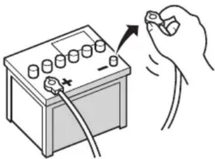
- Toavoidshortsintheelectricalsystem, be suretodisconnectthe(-)batterycablebeforeinstallation.

Topreventdamage

WARNING
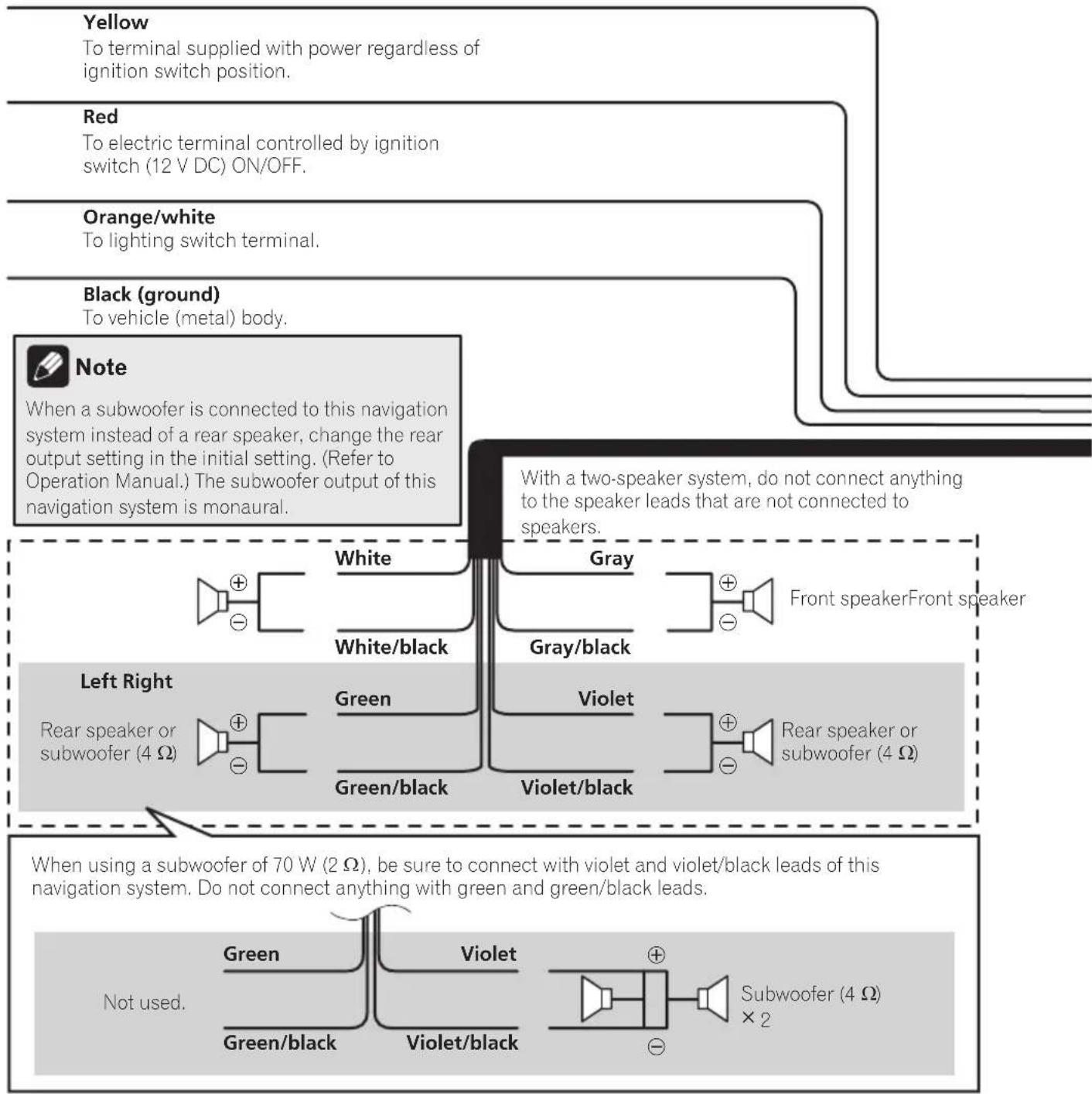
- Usespeakersover50W(outputvalue) andbetween4Ωto8Ω(impedancevalue). Donotuse1Ωto3Ωspeakersforthis unit.
Connectingthesystem
Theblackcableisground.Wheninstal- lingthisunitorpoweramp(soldsepar aately),makesuretoconnecttheground wirefirst.Ensurethatthegroundwire is properlyconnectedtometalpartsofthe car'sbody.Thegroundwireofthepower ampandtheoneofthisunitoranyother devicemustbeconnectedtothecarsepa ratelywithdifferent screws.Ifthescrew forthegroundwireloosensorfallsout,it couldresultinfiregenerationofsmokeormalfunction.
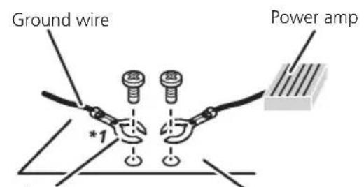
Other devices (Another electronic device in the car)
Metal parts of car's body
^*1 Not supplied for this unit.
-
When replacing the fuse, besuretoonly useafuseoftheratingprescribedonthis product.
-
Whendisconnectingaconnector, pull the connectoritself. Donotpullthelead, as youmaypullitoutoftheconnector.
- ThisproductcannotbeinstalledinvehiclewithoutACC(accsory)positionontheignitionswitch.
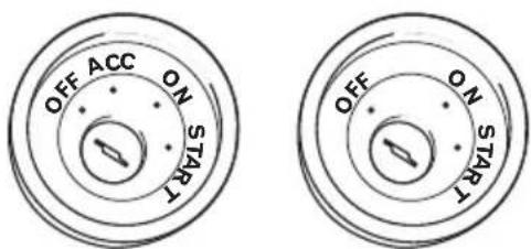
ACCpositionNoACCposition
-
Toavoidshort-circuiting,coverthedisconnectedleadwithinsulatingtape. ltisespeciallyimportanttoinsulateallunused speakerleads,whichfleftuncoveredmay causeashortcircuit.
-
Attachtheconnectorsoftthesamecolorto thecorrespondingcoloredport,i.e.,blue connectortotheblueport,blacktoback, etc.
- Refertotheowner's manualfordetailson connectingthepowerampandootherunits, thenmakeconnectionsaccordingly.
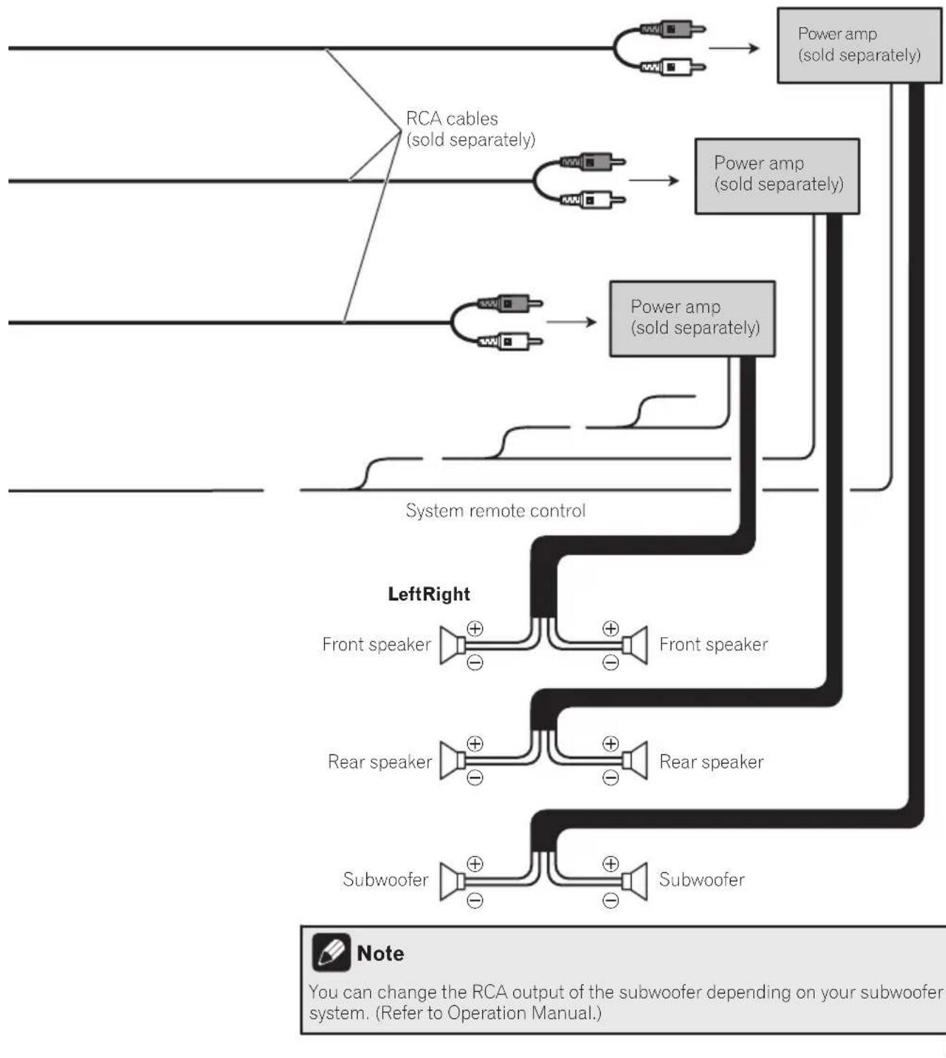
- SinceauniqueBPTLCircuitisemployed, donotdirectlygroundthe sideofthespeakerleadorconnectthe sideofan-othersideofthespeakerleadtogether.Be suretoconnectthe sideofthespeaker leadtothe sideofthespeakerleadon thisnavigationsystem.
- IftheRCApinjackonthisproductwillnot beused, donotremovethecapsattached totheendofthecnector.
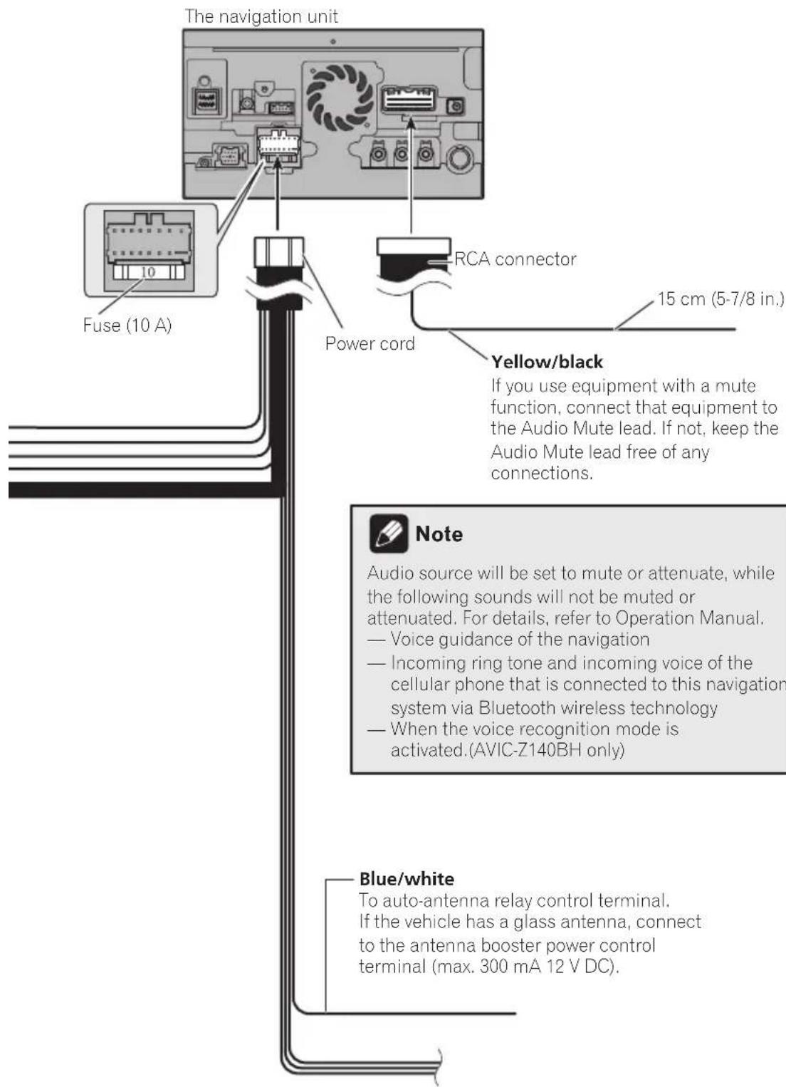
Noticefortheblue/whitelead
- Whentheignitionswitchisturnedon(ACC ON), a controlsignalisoutputthre blue/whitelead. Connecttoanexternal poweramp'systemremotecontrolterminal, theauto-antennarelaycontrolterminal, ortheantennaboosterpowercontrol terminal (max.300mA12VDC). The controlsignalisoutputthrougtheblue/white lead, eveniftheaudiosourceisswitched off.
- Besurenottousethisleadasthepower supplyleadforthexternalpoweramps. Suchconnectioncouldcauseexcessive currentdrainandmalfunction.
- Besurenottousthisleadasthepower supplyleadfortheauto-antennaorantenaboofter.Suchconnectioncouldcause excessivecurrentdrainandmalfunction.

Connectingthesystem
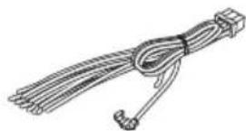
Partssupplied
AVIC-Z140BH
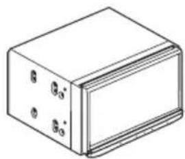
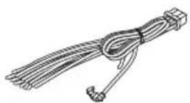
ThenavigationunitPowercord
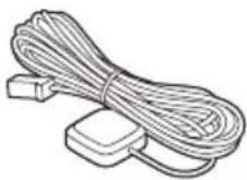
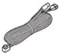
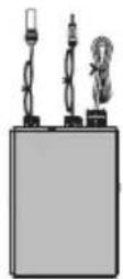
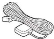
TraffictunerGPSantenna
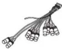
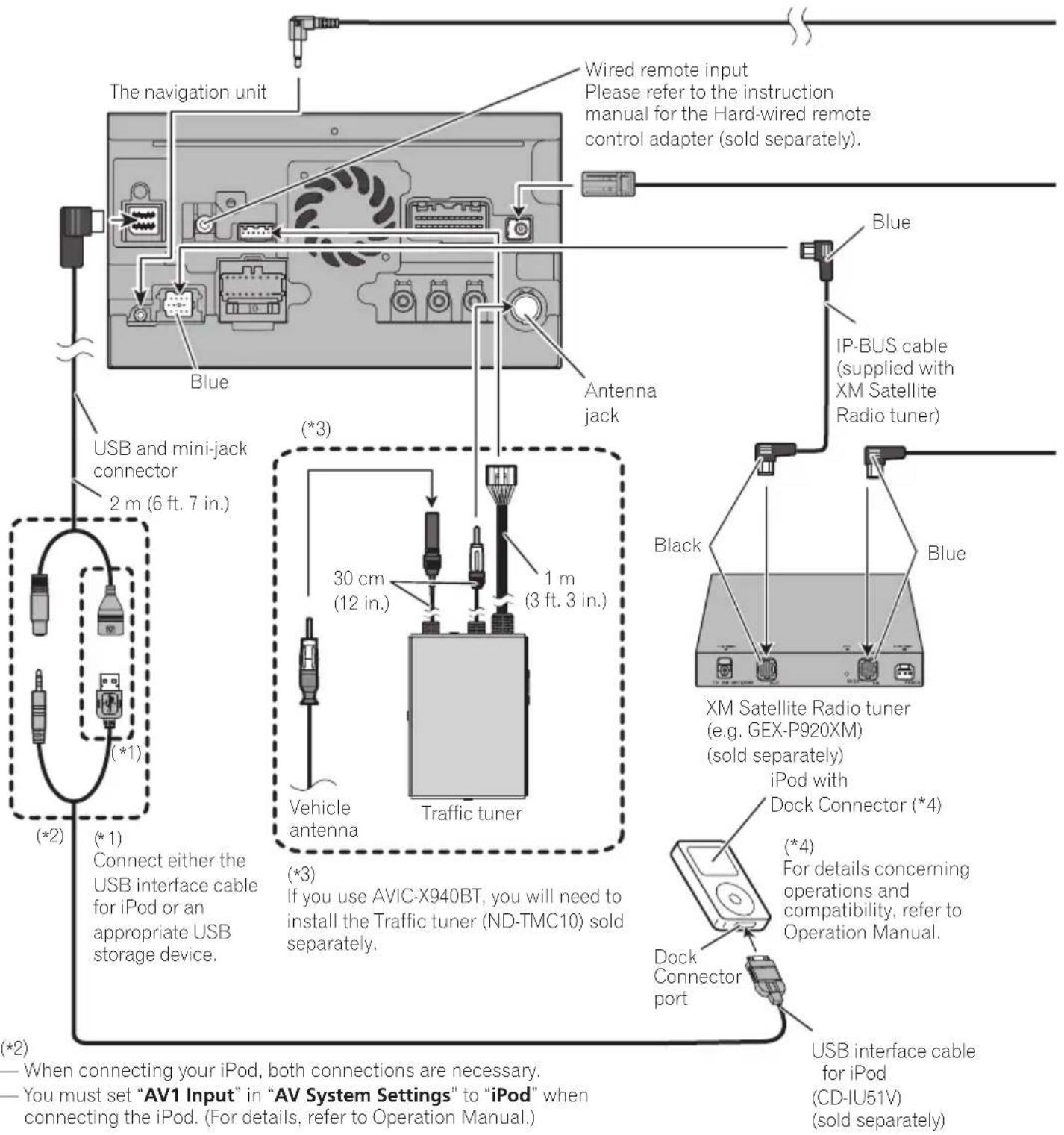
USBandmini-jack connector
RCAconnector
AVIC-X940BT
ThenavigationunitPowercord
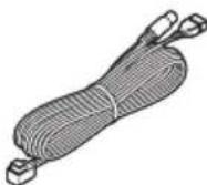
GPSantennaUSBandmini-jack
connector
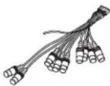
RCAconnectorMicrophone

Connectingthesystem
Connectingthesystem
Connectingthesystem
Connectingthesystem
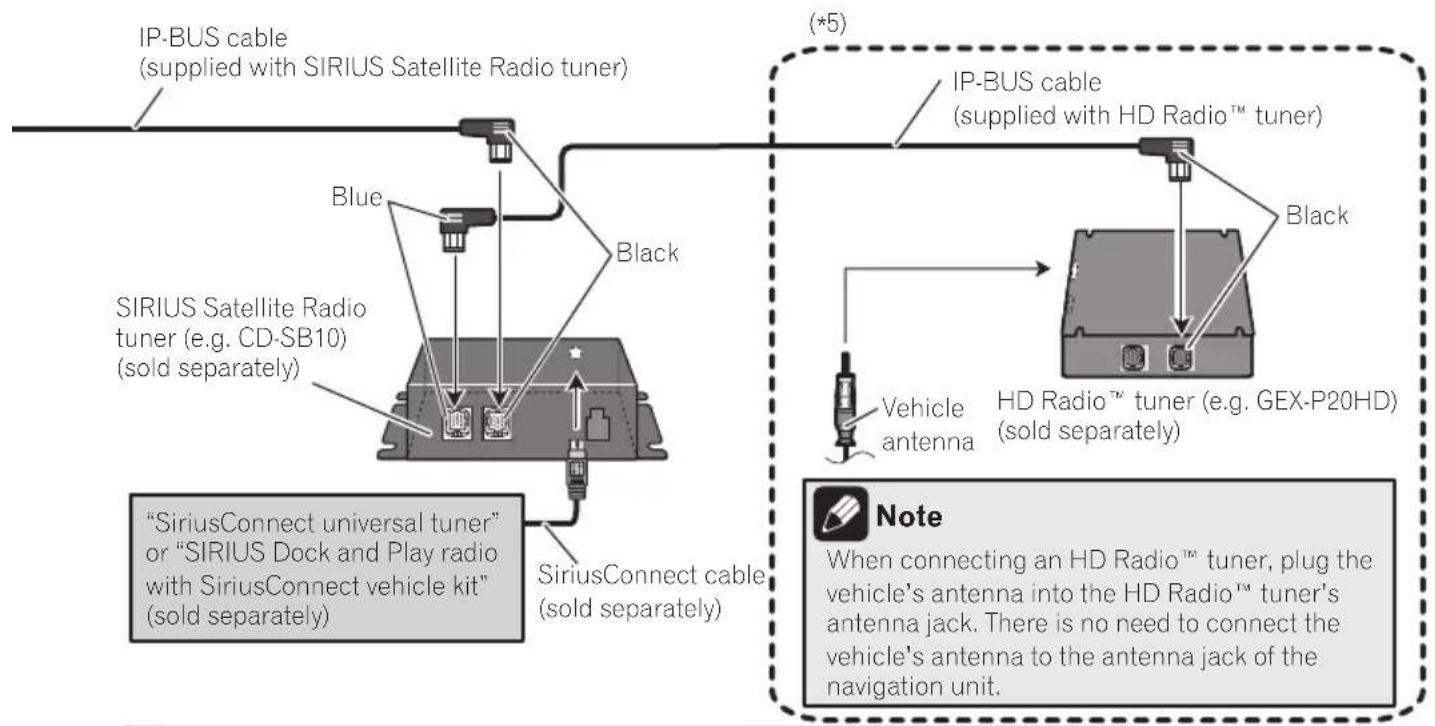
(^*5)
The AVIC-Z140BH is equipped with a built-in HD Radio™ tuner, which makes installation of an additional tuner unnecessary. However, if you use the AVIC-X940BT, you will need to install a HD Radio™ tuner.

WARNING
- To avoid the risk of accident and the potential violation of applicable laws, this product should never be used while the vehicle is being driven except for navigation purposes. And, also rear displays should not be in a location where it is a visible distraction to the driver.
- In some countries, the viewing of images on a display inside a vehicle even by persons other than the driver may be illegal. Where such regulations apply they must be obeyed and this product's video source should not be used.

Connectingthepowercord(1)
Connectingthesystem

Connectingthesystem
Connectingthepowercord(2)
Pink (CAR SPEED SIGNAL INPUT)
The navigation system is connected here to detect the distance the vehicle travels. Always connect the vehicle's speed detection circuit. Failure to make this connection will increase errors in the vehicle's location display.

WARNING
IMPROPER CONNECTION MAY RESULT IN SERIOUS DAMAGE OR INJURY INCLUDING ELECTRICAL SHOCK, AND INTERFERENCE WITH THE OPERATION OF THE VEHICLE'S ANTILOCK BRAKING SYSTEM. AUTOMATIC TRANSMISSION AND SPEEDOMETER INDICATION.

CAUTION
It is strongly suggested that the speed pulse wire be connected for accuracy of navigation and better performance.

Note
The position of the speed detection circuit and the position of the parking brake switch vary depending on the vehicle model. For details, consult your authorized Pioneer dealer or an installation professional.
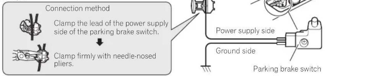
Light green (PARKING BRAKE)
Used to detect the ON/OFF status of the parking brake. This lead must be connected to the power supply side of the parking brake switch.
If this connection is made incorrectly or omitted, certain functions of your navigation system will be unusable.

WARNING
LIGHT GREEN LEAD AT POWER CONNECTOR IS DESIGNED TO DETECT PARKED STATUS AND MUST BE CONNECTED TO THE POWER SUPPLY SIDE OF THE PARKING BRAKE SWITCH. IMPROPER CONNECTION OR USE OF THIS LEAD MAY VIOLATE APPLICABLE LAW AND MAY RESULT IN SERIOUS INJURY OR DAMAGE.
Connectingthesystem

Whenconnectingto separatelysoldpoweramp
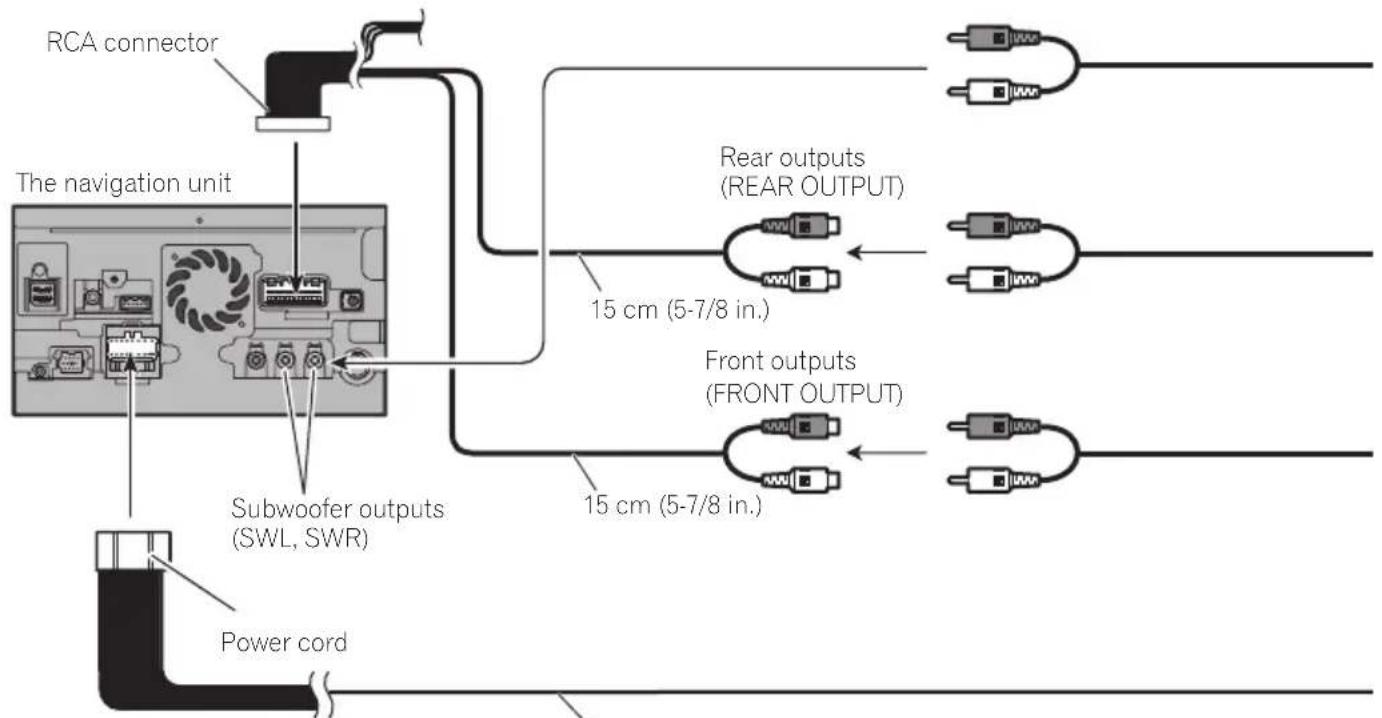
Blue/white
To system control terminal of the power amp (max. 300 mA 12 V DC).
Connectingthesystem
Connectingthesystem
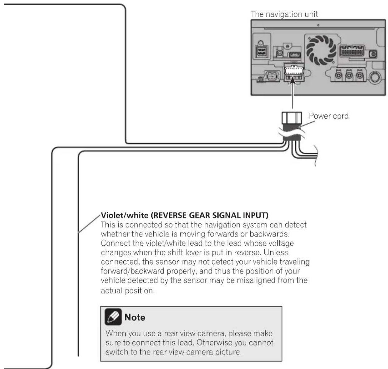
Whenconnectingarear viewcamera
Whenthisproductususedwitharearview camera,itispossibletoautomaticallyswitch fromthevideotorearviewimagewhenthe shiftleverismovedtoREVERSE(R).Rear Viewmodealsoallowsyoutocheckwhatis behindyouwhiledriving.

WARNING
USEINPUTONLYFORREVERSEORMIRROR
IMAGEREARVIEWCAMERA.OTHERUSEMAY
RESULTINJURYORDamage.

CAUTION
- Thescreenshotimagemayappearreversed.
Therearviewcamerasisusedasanaidto keeppaneyeontrailers,orbackingintoatight parkingspot.Donotusethisfunctionforentertainmentpurposes. - Objectsinrearviewmayappearcloserormoredistantthaninreality.
- Please notethat the imageareashown by the rearviewcameramaydifferslightlywhen full-screenimagesaredisplayed when backing andwhen checkingtherearofthevehicle whilemovingforward.
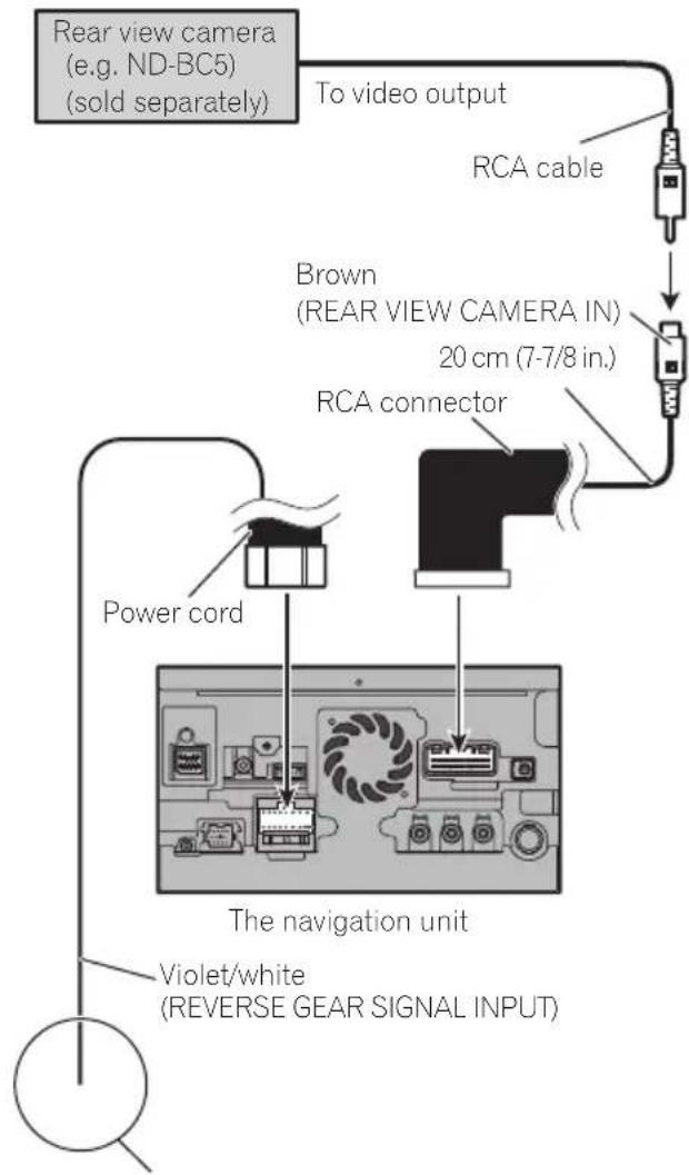
Formoredetailsaboutthewiring,refertoConnecting thepowercord(2)onpage12.

Notes
- Thismodeisavailablewhentherearview camerasettingissetto"On".(Fordetails, refereToOperationManual.)
- Connectthenavigationsystemtotherear viewcameraonly.Donotconnecttoany otherwise equipment.
Connectingthesystem
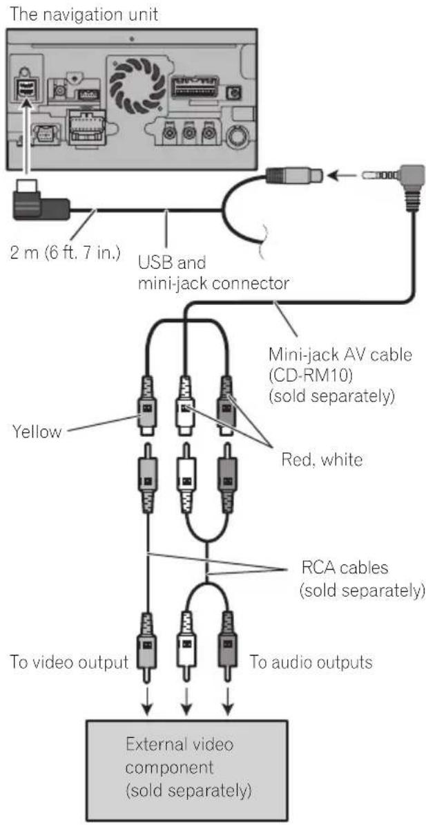
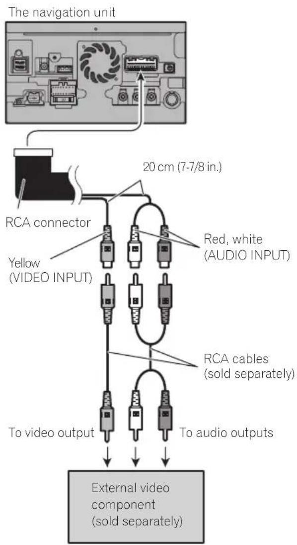
Whenconnecting the externalvideocomponent UsinganAVinput(AV1)
- You must set "AV1 Input" in "AV System Settings" to "Video" when connecting the externalvideocomponent.(Fordetails, refereToOperationManual.)
CAUTION
Besuretouseamini-jackAVcable(CD-RM10) (soldseparately)forwiring.Ifyouuseother cables,thewiringpositionmightdifferresulting indisturbedimagesounds.
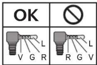
L: Left audio (White)
R:Rightaudio(Red)
V: Video (Yellow)
G:Ground
UsinganAVinput(AV2)
- You must set "AV2 Input" in "AV System Settings" to "Video" when connecting the externalvideocomponent.(Fordetails, refereToOperationManual.)
Whenconnectingthereardisplay
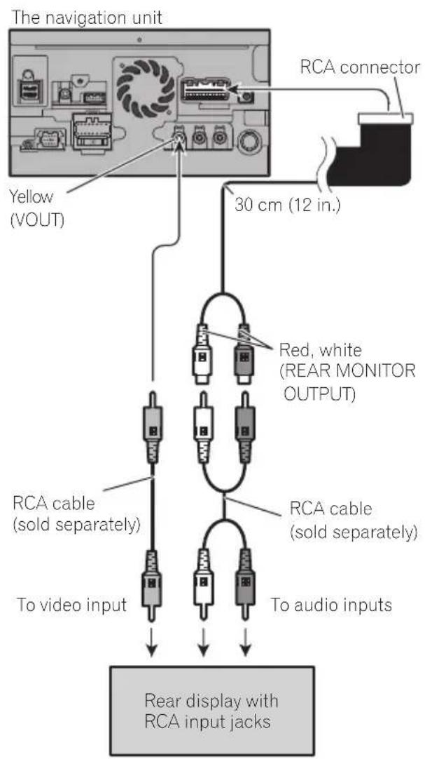
Whenusingareardisplay connectedorearvideooutput
WARNING
NEVERinstallthereardisplayalocation thatenablesthedrivertowatchthevideo sourcewhiledriving.
This navigationsystem'searvideooutputisfor connectionofadisplaytoenablepassengersintherearseatstowatchthevideosource.
Whenconnectingtheexternal unitfeaturingvideosource
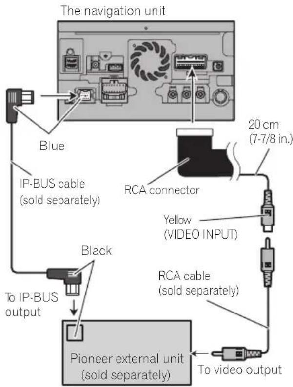
- You must set "AV2 Input" in "AV System Settings" to "EXT" when connecting the externalunit.(Fordetails,refertoOperation Manual.)
Precautionsbefore installation

CAUTION
- Neverinstallthisproductinplaceswhere, orinamannerthat:
—Couldinjurethedriverorpassengersif thevehiclestopssuddenly.
Mayinterferewiththedriver'soperationofthevehicle,suchasonthefloorinfrontofthedriver'sseat,orclosetothesteeringwheelorshiftlever. - Makesurethereisnothingbehindthedashboardorpanelingwhendrillingholesinthem.Becarefulnottodamagefuellines,brakelines,electroniccomponents,communicationwiresorpowercables.
- Whenusingscrews, donotallowthem to comeintocontactwithanyelectricallead. Vibrationmaydamagewiresorinsulation, leadingtoashortcircuitorotherdamage tothevehicle.
Toensureproperinstallation,besureto usethesuppliedpartsinthemannerspecified.Ifanypartsarenotsuppliedwith thisproduct,usecompatiblepartsinthe mannersspecifiedafteryouhavetheparts' compatibilitycheckedbyyourdealer.If partsotherthansuppliedorcompatible onesareused,theymaydamageinternal partsofthisproductortheymaywork looseandtheproductmaybecomdetached. - Itisextremelydangeroustoallowcables tobecomewoundaroundthesteeringcolumnorshiftlever.Besuretoinstallthis product,itscables,andwiringawayinsuchsothattheywillnotobstructorhinderdriving.
- Makesurethatleadscannotgetcaughtin adoorortheslidingmechanismofaseat, resultinginashortcircuit.
-
Please confirm the proper function of your vehicle's other equipment after installation of then navigationsystem.
-
Donotinstallthisnavigationsystem whereitmay(i)obstructthedriver'svision,(ii)impairtheperformanceofanyof thevehicle'soperatingsystemsafety features,includingairbags,hazardlamp buttonstor(ii)impairthedriver'sability to safely operate thevehicle.
Installthenavigationsystembetweenthe driver'sseatandfrontpassengerseatso thatitwillnotbehitbythederiverorpassengerifthevehiclestopsquickly. - Neverinstallthenavigationsystemin frontofornexttotheplaceinthedashboard,door,orpillarfromwhichoneof yourvehicle'sairbagswoulddeploy. Please refer to your vehicle's owner's manualforreferencectothedeployment areaofthefrontalairbags.
Toavoidelectromagnetic interference
Inordertopreventinterference,setthefollowingitemsasfaraspossiblefromthisnavigationsystem,othercablesorleads:
FM,AMantennaanditslead
GPSantennaanditslead Inaddition,youshouldlayorrouteeachantennaleadasfaraspossiblefromotherantenaleads.Donotbind,layorroutethem together,orcrossthem.Electromagnetic noisewillincreaseathepotentiaforerrorsin thevehicle'slocationdisplay.
Beforeinstalling
- ConsultwithyournearestdealerinstallationrequiresdrillingholesorthermodificatiOnsofthevehicle.
- Beforemakingafinalinstallationofthis product, temporarilyconnectthewiringto confirmthattheconnectionsarecorrect andthesystemworksproperly.
Installation
ForAVIC-Z140BHusers
DonotinstallthisnavigationsysteminpositionwhereetheopeningoftheLCDpanelisobstructedbyanyobstacles,suchastheshiftlever.Beforeinstallingthisnavigationsystem, besuretoavesuicficientspacesothatthe LCDpaneldoesnotobstructtsheshiftlever whenitisfullyopened.Thismaycauseinterferencewiththeshiftlever,oramalfunctionof themechanismofthisnavigationsystem.
Installingthenavigation system
Installationnotes
- Donotinstallthenavigationsystemin
- placc subjecttohighttemperaturesorhumidity, suchs:
-Placesclosetoahater,ventorairconditioner.
—Placesexposedtodirectsunlight,such asontopofthedashboard.
-Placesthatmaybeexposedtorain, suchasclosetothedoororonthevehicle'sfloor.
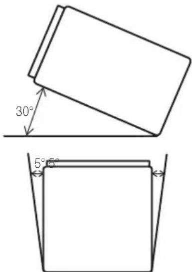
Installthisnavigationsysteminanare a strongenoughtobearitsweight.Choosea positionwherethisnavigationsystemcan befirmlynstalled,andinstallitsecurely.If thisnavigationsystemisnotsecurelyinstalled,thecurrentlocationofthevehicle cannotbedisplayedcorrectly.
Installthenavigationunithorizontallyona surfacewithin0to30degreestolerance (within5degreestotheleftorright).Improperinstallationoftheunitwiththesurface tiltedmorethanthesetolerancesincreases thepotentialforerrorsinthevehicle'slocationdisplay,andmightotherwisecausereduceddisplayperformance.
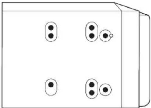
- Wheninstalling, toensureproperheatdispersalwhenusingthisunit, makesureyou leaveamplespacebehindtherearpanel andwrapanyloosecablessotheyarenot blockingthevents.

Thecordsmustnotcovertheareashown inthefigurebelow.Thisisnecessaryto allowtheamsandnavigationmechanism todissipateheat.
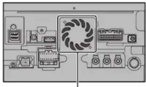
Donotcoverthisarea.
- Thesemiciconductor laser will be damaged if it over heats, sodon't install then navigation unit anywhere hot—for instance, near a theater outlet.
Partssupplied
Partsmarked(*)aresuppliedwithAVIC-X940BT.

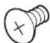
ThenavigationunitTrussheadscrew (5mm×8mm) (6pcs.)
Flushsurfacedcrew (5mm×9mm) (6pcs.)

Screw* (2mm×4mm) (1pc.)
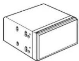
Installationusingthescrewholes onthesideofthenavigationunit
Fasteningthenavigationunittothe factoryradio-mountingbracket.
Positionthenavigationunitsothathebracketsscrewwholesanditscrewholesare aligned,andtightentheshrewsatthreelocationsoneachside.
Useeitherthetrussheadscrews(5mm× 8mm)orflushsurfacedcrews(5mm× 9mm),dependingontheshapeofthebracket'sscrewholes.
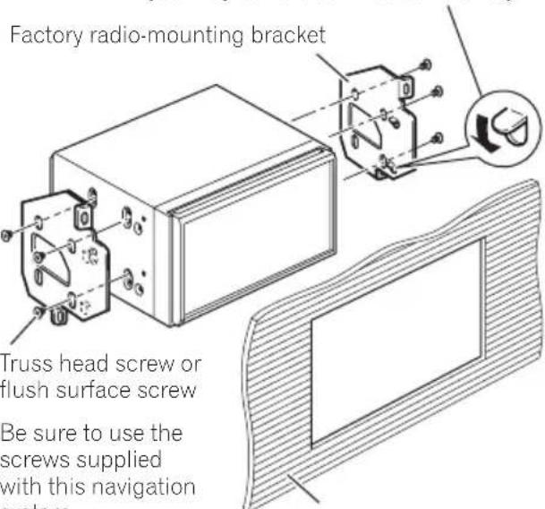
If the pawl interferes with installation, you may bend it down out of the way.
Dashboard or console
Installation
Fasteningthedetachablefaceplate
This description is for AVIC-X940BT. If youdonot plantoremovethedetachablefaceplate, thedetachablefaceplate can be fastened with the supplied screw.
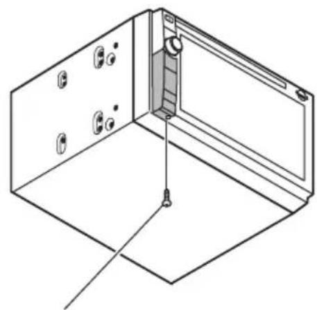
Screw(2mm×4mm)

InstallingtheGPSantenna
CAUTION
DonotcuttheGPSantennaleadtoshorten itoruseanextensionomakeitlonger.Alteringtheantennacablecouldresultinashort circuitormalfunctionandpermanentdamagetothenavigationsystem.
Installationnotes
- Theantennashouldbeinstalledonalevel surfacewhereradiowaveswillbeblocked aslittleaspossible.Radiowavescannotbereceivedbytheantennafreecctionfrom thesatelliteisblocked.
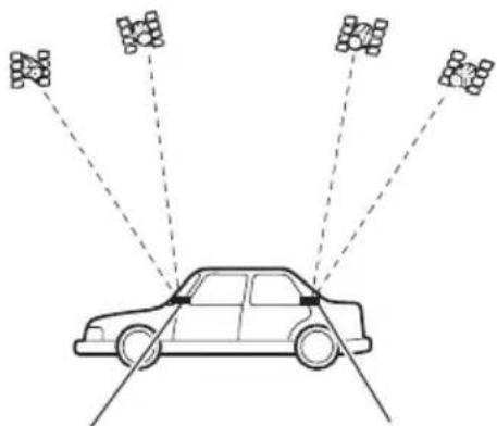
DashboardRearshelf
- WheninstallingtheGPSantennainside thevehicle, besuretousethemetalsheet providedwithyoursystem. Ifthisisnot used, thereceptionsensitivitywillbepoor.
- Donotcuttheaccessorymetalsheet.This would reduce the sensitivity of the GPS antenna.
Takecarenottopulltheantennaleadwhen removingtheGPSantenna.Themagnetattachedtotheantennaisverypowerful,and theleadmaybecomedetached. - DonotpainttheGPSantenna, asthismay affectsperformance.
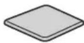
Partssupplied
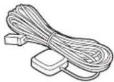
GPSantennaMetalsheet
Wheninstallingtheantennainsidethevehicle(onthedashboard orrearshelf)

WARNING
DonotinstalltheGPSantennaoveranysensorsorventsonthedashboardofthevehicle,asdoingsomayinterferewiththeproperfunctioningofsuchsensorsorventsandmaycompromisetheabilityofthemetalsheetundertheGPSantennatproperlyandsecurelyaffixtothedashboard.
Affixthemetalsheetonthesurfaceaslevelas possiblewheretheGPSantennafacethe window.PlacetheGPSantennaonthemetal sheet.(TheGPSantennaisfastenedwithits magnet.)
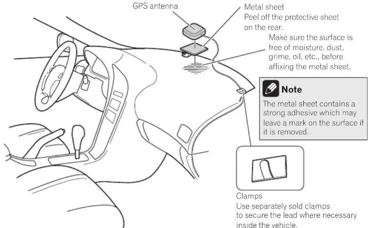
Clamps
Use separately sold clamps to secure the lead where necessary inside the vehicle.

Notes
- Whenattachingthemetalsheet, donotcut itintosmallpieces.
- Somemodelsusewindowglasssthatdoesn'tallowssignalsfromGPSsatellitestopassthrough.Onsuchmodels,installtheGPSantennaontheoutsideofthevehicle.

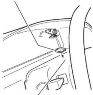
Installingthemicrophone
Installhemicrophoneinaplacewhereits directionanddistancefromthedriver makeiteasiesttopickupthedriver'svoice.
- Makesuretoconnectthemicrophonetohthenavigationsystemafterthesystemisturnedoff(ACCOFF).
Partssupplied
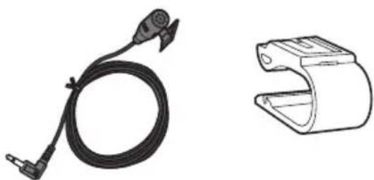
MicrophoneMicrophoneclip

Double-sidedtape
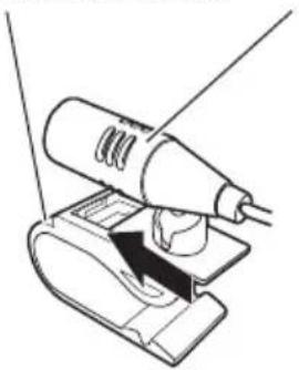
Mountingonthesunvisor 1Installhemicrophoneinthemicrophoneclip.
MicrophoneclipMicrophone

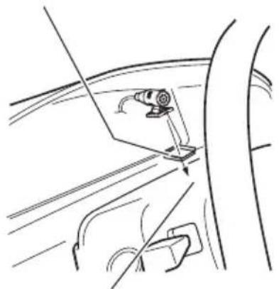
2Attachemicrophonecliptothesun visor.
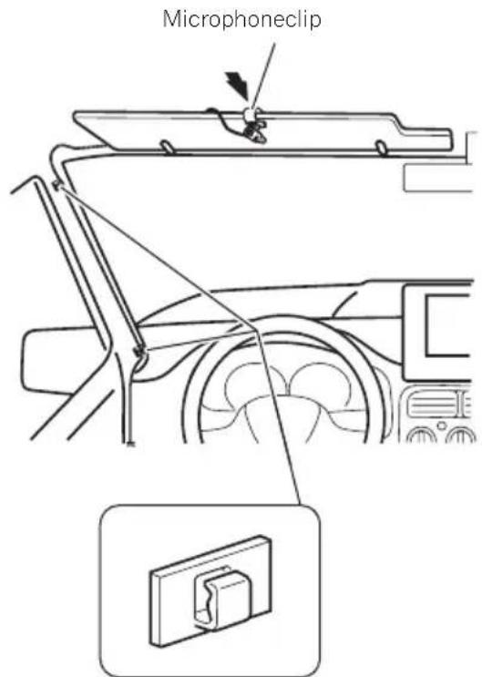
Clamps Useseparatelysoldclamps tosecuretheleadwhererecessaryinsidethevehicle.
Installthemicrophoneonthesunvisorwhen itisintheupposition.Itcannotrecognizethe driver'svoiceifthesunvisorisinthedownposition.
Installation
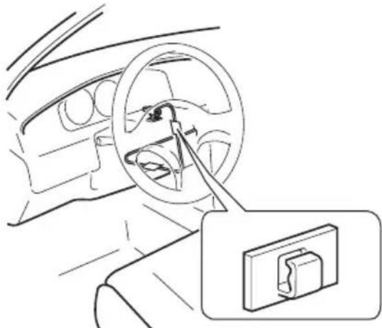
Installationonthesteeringcolumn
- Mountthemicrophoneonthesteering column.
Double-sidedtape
Installthemicrophoneonthe steeringcolumn,keepingitaway fromthesteeringwheel.
Clamps
Useseparatelysold
clampstosecarethe
leadwherenecessary
insidethevehicle.
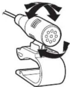
Adjustingthemicrophoneangle
Themicrophoneanglecanbeadjusted.


Précautions
Votrenouveausystémedenavigationetcm
manuel29
Importantmesuresdesecurite29

Installationdumicrophone54
-Piècesfournies54
-Installationsurlepare-soleil54
-Installationsurlacolonned direction55
-Réglagedel'angledumicrophone56
Votrenouveausystemedennavigationetcemanuel
Installationdumicrophone
Installationsurlepare-soleil
1Installezlemicrophonedansl'agrafe pourmicro.
AgrafepourmicroMicrophone
Installationsurlacolonned direction
Montezlemicrophonesurlacolonne dedirection.
Bandeadhésiveadoubleface
Installezlemicrophonesurlacol- lonnencedirection,adistancedu volant.
PIONEERELECTRONICSAUSTRALIAPTY.LTD.
5ArcoLane,Heatherton,Victoria,3202,Australia
TEL:(03)9586-6300
PIONEERELECTRONICSOCANADA,INC.
340FerrierStreet,Unit2,Markham,OntarioL3R2Z5,Canada
TEL:1-877-283-5901
TEL:905-479-4411
PIONEERELECTRONICSDEMEXICO,S.A.deC.V.
Blvd.ManuelAvilaCamacho13810piso
Col.LomasdeChapultepec, Mexico, D.F. 11000
TEL:55-9178-4270
先锋股份有限公司
台北市內湖區瑞光路407號8樓
©2011PIONEERCORPORATION.
Allrightsreserved.
©2011PIONEERCORPORATION.

- Installation
- Yournewnavigation systemandthismanual
- Important safeguards 工 WARNING
- Precautionsbefore connectingthesystem
- CAUTION
- Beforeinstallingthisproduct
- Topreventdamage
- WARNING
- Connectingthesystem
- Partssupplied
- AVIC-Z140BH
- AVIC-X940BT
- (*5)
- Connectingthepowercord(1)
- Connectingthepowercord(2)
- Pink (CAR SPEED SIGNAL INPUT)
- Note
- Light green (PARKING BRAKE)
- Whenconnectingto separatelysoldpoweramp
- Blue/white
- Whenconnectingarear viewcamera
- Notes
- Whenconnecting the externalvideocomponent UsinganAVinput(AV1)
- UsinganAVinput(AV2)
- Whenconnectingthereardisplay
- Whenusingareardisplay connectedorearvideooutput
- Whenconnectingtheexternal unitfeaturingvideosource
- Precautionsbefore installation
- Toavoidelectromagnetic interference
- Beforeinstalling
- ForAVIC-Z140BHusers
- Installingthenavigation system
- Installationnotes
- Installationusingthescrewholes onthesideofthenavigationunit
- Fasteningthenavigationunittothe factoryradio-mountingbracket.
- Fasteningthedetachablefaceplate
- InstallingtheGPSantenna
- Wheninstallingtheantennainsidethevehicle(onthedashboard orrearshelf)
- Clamps
- Installingthemicrophone
- Mountingonthesunvisor 1Installhemicrophoneinthemicrophoneclip.
- 2Attachemicrophonecliptothesun visor.
- Installationonthesteeringcolumn
- Adjustingthemicrophoneangle
- Précautions
- Votrenouveausystemedennavigationetcemanuel
- Installationdumicrophone
- Installationsurlepare-soleil
- Installationsurlacolonned direction
- PIONEERELECTRONICSAUSTRALIAPTY.LTD.
- PIONEERELECTRONICSOCANADA,INC.
- PIONEERELECTRONICSDEMEXICO,S.A.deC.V.
- 先锋股份有限公司
Brand : PIONEER
Model : AVICZ140BH
Category : GPS Navigation System