
PRO530 - Surveillance Camera SWANN - Free user manual and instructions
Find the device manual for free PRO530 SWANN in PDF.
| Product type | Surveillance camera |
| Brand | Swann |
| Model | PRO530 |
| Image sensor | 1/3" CMOS |
| Video quality | 600 TV lines |
| Effective pixels | 728 x 488 |
| Minimum illumination | 0 Lux (IR active) |
| Day/night mode | Yes, with movable IR filter |
| Viewing angle | 58 degrees |
| Night vision distance | 20 m (65 ft) |
| Number of IR LEDs | 24 (wavelength 850 nm) |
| Power supply | DC 12 V |
| Operating temperature | -20 °C to 60 °C |
| Housing material | Aluminum |
| Dimensions (camera only) | 50 x 50 x 70 mm |
| Dimensions (with bracket) | 65 x 65 x 145 mm |
| Weight (with bracket) | 253 g |
| Indoor/outdoor use | Both |
| Package contents (single camera pack) | 1 camera, 1 extension cable, mounting screws, power adapter, security stickers, quick start guide |
| Main functions | Night vision, movable IR filter, backlight compensation, 3-point articulating mount |
| Maintenance and cleaning | Clean with a soft, dry cloth |
| Safety | Complies with local regulations; unauthorized modifications void compliance |
| Warranty | 1 year against manufacturing defects |
Frequently Asked Questions - PRO530 SWANN
User questions about PRO530 SWANN
0 question about this device. Answer the ones you know or ask your own.
Ask a new question about this device
Download the instructions for your Surveillance Camera in PDF format for free! Find your manual PRO530 - SWANN and take your electronic device back in hand. On this page are published all the documents necessary for the use of your device. PRO530 by SWANN.
USER MANUAL PRO530 SWANN
natural_image
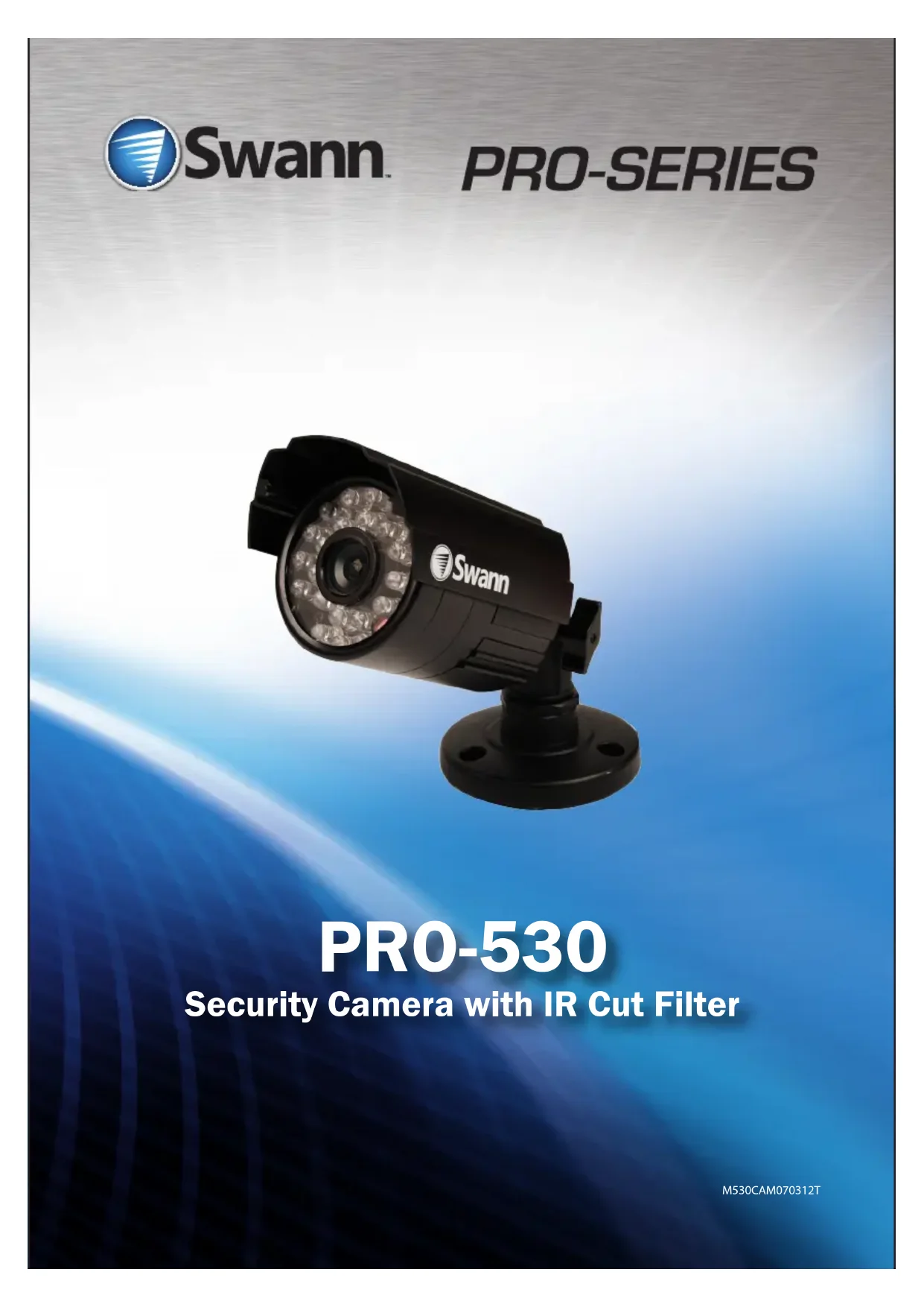
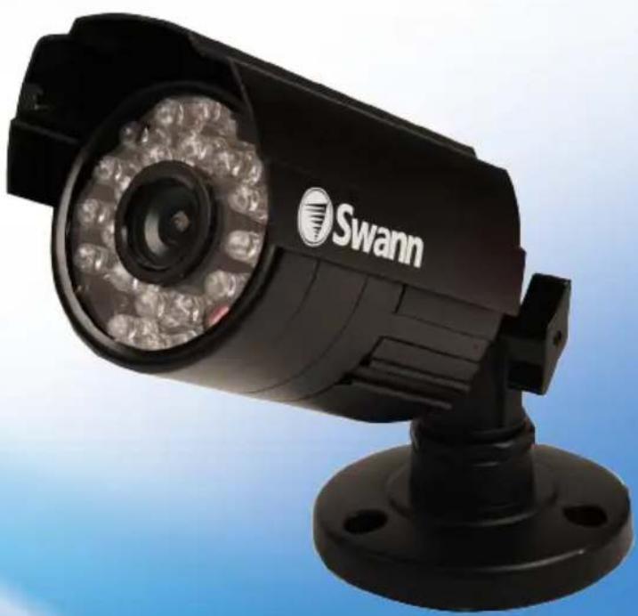
Black Swann surveillance camera with LED array and mounting base (no text or symbols visible on device body)PRO-530
Security Camera with IR Cut Filter
Before you begin
Introduction
Congratulations on your purchase of this PRO-530 indoor/outdoor day & night CCTV camera from Swann. The PRO-530 is a color CMOS camera that can operate in almost all lighting conditions, from bright daylight (provided it's not pointed straight toward the sun!) to pitch darkness.
The PRO-530 is very sensitive to light and therefore can make use of even the smallest amount of light to provide an image of what it sees. In low light, this comes through as a black and white image.
In complete or near-total darkness, the camera uses built-in infrared LEDs to illuminate the area in front of it. This light is invisible to the human eye, although you might notice a faint red glow coming from the front of the camera - this is normal.
In day or well lit environments, the IR Cut Filter feature of the camera activates to filter out wavelengths of light the camera does not need in order to provide a clear color image.
IMPORTANT NOTE:
All jurisdictions have specific laws and regulations relating to the use of cameras. Before using any camera for any purpose, it is the buyer's responsibility to be aware of all applicable laws and regulations that prohibit or limit the use of cameras and to comply with the applicable laws and regulations.
WARNING: Modifications not approved by the party responsible for compliance could void user's authority to operate the equipment.
IMPORTANT SAFETY INSTRUCTIONS:
• Make sure product is fixed correctly and stable if fastened in place
- Do not operate if wires and terminals are exposed
Package Contents
Pack contents:
You may have purchased your PRO-530 as a standalone camera or as part of a pack. This will dictate the expected contents you should have received with your camera.
| Item Single camera 2 camera pack 3 camera pack 4 camera pack | ||||
PRO-530 camera 1 2 3 4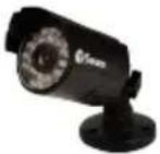 | ||||
Extension cable 1 2 3 4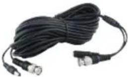 | ||||
Screws and wall plug package | 1 2 3 4 | |||
Power Adapter 1 1 (with 2-way | power splitter cable) | 1 (with 4-way power splitter cable) | 1 (with 4-way power splitter cable) | |
Security stickers 4 4 4 | ||||
Operating Instructions | 1 1 1 1 | |||
Connection Guide
natural_image
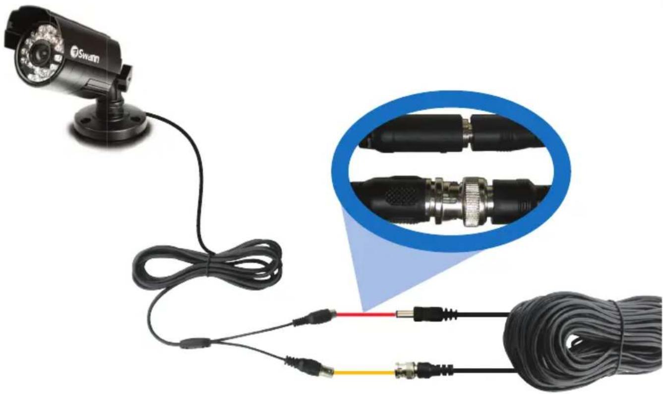
Close-up of a security camera connected to two cables with connectors, shown in close-up (no text or symbols visible)Connect the camera's DC and BNC socket cable to the extension cable's DC and BNC plugs
2A. Connecting Directly to TV
2 Connect a BNC to RCA adapter and connect to video input on your TV or VCR
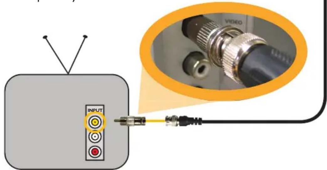
text_image
INPUT VIDEOConnection Guide
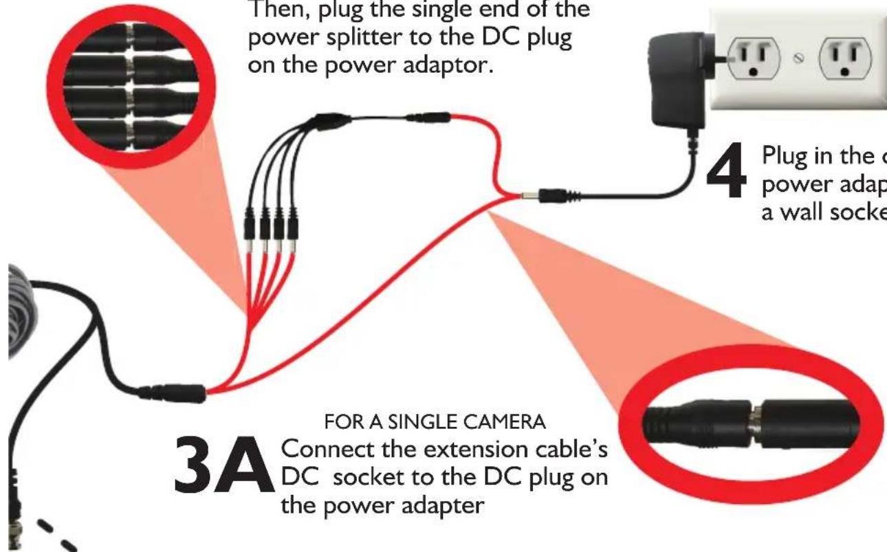
3B
FOR 4 CAMERA PACKS
Connect the extension cable's DC socket to one of the four sockets on the power splitter.
Then, plug the single end of the power splitter to the DC plug on the power adaptor.
text_image
Then, plug the single end of the power splitter to the DC plug on the power adaptor. 4 Plug in the c power adap a wall socke 3A FOR A SINGLE CAMERA Connect the extension cable's DC socket to the DC plug on the power adapter4
Plug in the camera power adapter into a wall socket
3A
FOR A SINGLE CAMERA
Connect the extension cable's DC socket to the DC plug on the power adapter
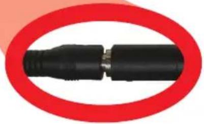
natural_image
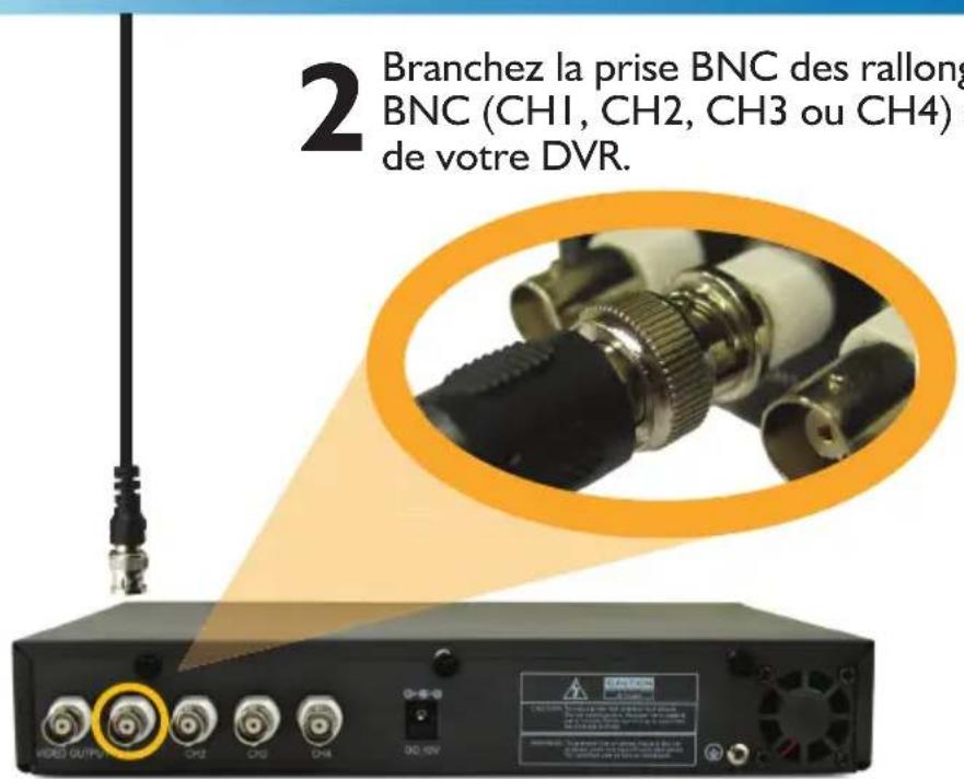
Close-up of a black plastic connector with metallic pins, enclosed in a red circular border (no text or symbols visible)2B. Connecting to Your Existing DVR
2
Connect the BNC extension cable to an open channel on the back of the DVR
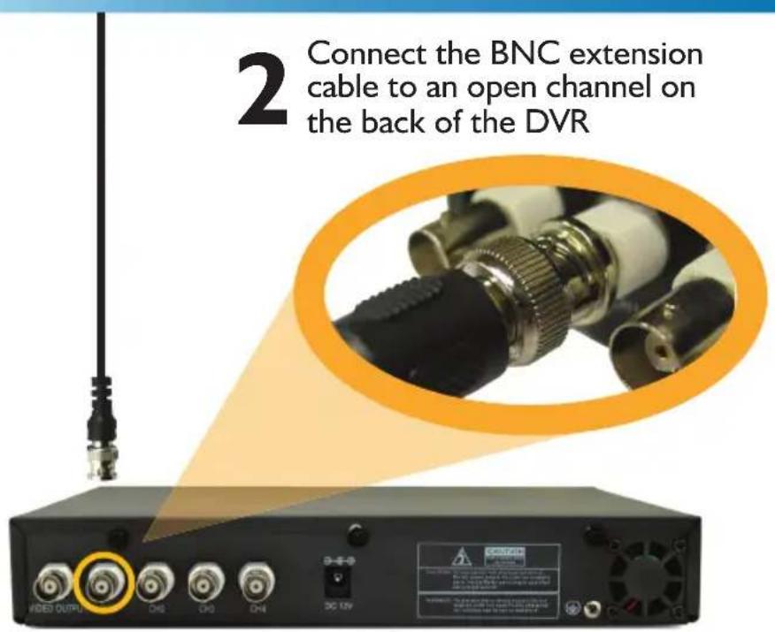
text_image
2 Connect the BNC extension cable to an open channel on the back of the DVRMounting the camera
text_image
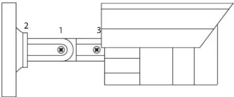
2 1 3The stand on the PRO-530 is deceptively adaptable. At first glance it may appear to limit how many options you have when mounting and aiming the camera, but this is simply untrue. The PRO-530 stand is almost infinitely adaptable – it's like the Rubik's Cube of CCTV camera stands!
You've got three points of articulation. The most obvious is the thumb screw-secured elbow joint in the centre of the stand (1). This one is pretty obvious and straight forward – loosen the screw, adjust to the position you want, and then tighten the screw again to secure in place.
The second point of articulation (2) is the radial joint where the neck of the stand attaches to the base. To adjust this joint, loosen the locking ring by rotating counter-clockwise. Rotate the camera and stand to the position you want then tighten the locking ring. By using articulation points 1 and 2, you can aim the camera in virtually any direction.
Point 3, located where the camera attaches to the stand, is held in place by one locking screw. Like point 2, it is a radial joint, allowing you to rotate the camera so that no matter how points 1 and 2 are configured, the camera can still face upright. Simply loosen the screw, rotate the camera to the upright position (so that up in your pictures is actually up) then tighten the screw to lock into place.
Of course, there will always be some outlying cases where the camera and stand simply won't fit where you want to mount them. Maybe you have a hanging awning, or a drain pipe in an inconvenient spot. In these cases, we suggest obtaining a mounting bracket, which should be available from any good hardware store.
Troubleshooting
| On my Swann DVR, ‘Video Loss’ appears where the image from my camera should be. | Check the extension cable (power and video) is securely connected to the camera.Check the video output from the camera is securely connected to a video input channel on the DVR.Check the power from the camera is securely connected to a power supply. |
| When I view an image from the camera at night I only see a bright spot and no image. | A reflection can be caused in night vision mode if the camera is looking through a window. Move the camera to the other side of the window or to another location. |
| The BNC extension cable will not connect to my TV. | Many TV’s and monitors do not have a BNC connector but do have an RCA connector. Connect a BNC to RCA adapter to the end of the extension cable and then plug into the RCA socket on your TV or monitor. |
| Video | Image Sensor 1/3" CMOS | |
| Video Quality 600 TVL | ||
| Resolution 728 x 488 | ||
| Minimum Illumination 0 Lux (IR on) | ||
| Day/Night Mode Color in lit areas / Black & White in dark areas | ||
| White Balance Automatic | ||
| Signal / Noise Ratio 45db | ||
| Gain Control Automatic | ||
| Backlight Compensation Yes | ||
| Lens 4.8mm | ||
| Viewing Angle 58 degrees | ||
| Night Vision | Night Vision Distance 65ft/20m | |
| IR Cut Filter YES | ||
| Infra-red LEDs 24 | ||
| Infra-red wavelength | 850nm | |
| Infra-red LED life (average) | 10,000 hours | |
| General | Indoor/Outdoor | Both |
| Operating Power | DC 12V | |
| Operating Temperature | -20°C ~ 60°C / 4°F ~ 140°F | |
| Body Construction | Aluminium | |
| Dimensions (without stand) | 50mm x 50mm x 70mm2.0" x 2.0" x 2.8" | |
| Dimensions (with stand) | 65mm x 65mm x 145mm2.5" x 2.5" x 5.7" | |
| Weight | 253g / 8.9oz |
Images are for illustrative purposes only. Specifications subject to change without notice. For the latest version of this manual, please visit:
www.swann.com
Helpdesk / Technical Support Details
Swann Technical Support
All Countries E-mail: tech@swannsecurity.com
Telephone Helpdesk
USA toll free
1-800-627-2799
(Su, 2pm-10pm US PT)
(M-Th,6am-10pm US PT)
(F 6am-2pm US PT)
USA Exchange & Repairs
1-800-627-2799 (Option 1)
(M-F, 9am-5pm US PT)
AUSTRALIA toll free
1300 138 324
(M 9am-5pm AUS ET)
(Tu-F 1am-5pm AUS ET)
(Sa 1am-9am AUS ET)
NEW ZEALAND toll free
0800 479 266
UK
0203 027 0979
See http://www.worldtimeserver.com for information on time zones and the current time in Melbourne, Australia compared to your local time.

Swann
Limited Warranty Terms & Conditions
Swann Communications warrants this product against defects in workmanship and material for a period of one (1) year from it's original purchase date. You must present your receipt as proof of date of purchase for warranty validation. Any unit which proves defective during the stated period will be repaired without charge for parts or labour or replaced at the sole discretion of Swann. The end user is responsible for all freight charges incurred to send the product to Swann's repair centres. The end user is responsible for all shipping costs incurred when shipping from and to any country other than the country of origin.
The warranty does not cover any incidental, accidental or consequential damages arising from the use of or the inability to use this product. Any costs associated with the fitting or removal of this product by a tradesman or other person or any other costs associated with its use are the responsibility of the end user. This warranty applies to the original purchaser of the product only and is not transferable to any third party. Unauthorized end user or third party modifications to any component or evidence of misuse or abuse of the device will render all warranties void.
By law some countries do not allow limitations on certain exclusions in this warranty. Where applicable by local laws, regulations and legal rights will take precedence.
For Australia: Our goods come with guarantees which cannot be excluded under Australian Consumer Law. You are entitled to a replacement or refund for a major failure and for compensation for any other reasonably foreseeable loss or damage. You are also entitled to have the goods repaired or replaced if the goods fail to be of acceptable quality and the failure does not amount to major failure.
FCC Verification
This equipment has been tested and found to comply with the limits for Class B digital device, pursuant to part 15 of the FCC Rules. These limits are designed to provide reasonable protection against harmful interference in a residential installation. This equipment generates, uses and can radiate radio frequency energy and, if not installed and used in accordance with the instructions, may cause harmful interference to radio or television reception, which can be determined by turning the equipment off and on, the user is encouraged to try to correct the interference by one or more of the following measures:
Reorient or relocate the receiving antenna
Increase the separation between the equipment and the receiver
- Connect the equipment into an outlet on a circuit different from that to which the receiver is connected
- Consult the dealer or an experienced radio/TV technician for help
WARNING: Modifications not approved by the party responsible for compliance could void user's authority to operate the equipment.

Swann
PRO-SERIES
natural_image
Black Swann surveillance camera with LED array and mounting base (no text or symbols visible on device body)PRO-530
natural_image
Close-up of a security camera connected to two cables with connectors, shown in close-up (no text or symbols visible)Swann Technical Support
All Countries E-mail: tech@swannsecurity.com
Telephone Helpdesk
USA toll free
1-800-627-2799
(Su, 2pm-10pm US PT)
(M-Th, 6am-10pm US PT)
(F 6am-2pm US PT)
USA Exchange & Repairs
1-800-627-2799 (Option 1)
(M-F, 9am-5pm US PT)
AUSTRALIA toll free
1300 138 324
(M 9am-5pm AUS ET)
(Tu-F 1am-5pm AUS ET)
(Sa 1am-9am AUS ET)
NEW ZEALAND toll free
0800 479 266
UK
0203 027 0979
See http://www.worldtimeserver.com for information on time zones and the current time in Melbourne, Australia compared to your local time.
Swann Communications USA Inc.
12636 Clark Street
Santa Fe Springs CA 90670
USA
Swann Communications
Unit 13, 331 Ingles Street,
Port Melbourne Vic 3207
Swann Communications LTD.
Stag Gates House
63/64 The Avenue
SO171XS
United Kingdom
© Swann Communications 2012
natural_image
Black Swann surveillance camera with LED array and mounting base (no text or symbols visible on device body)PRO-530
natural_image
Close-up of a surveillance camera connected to two black cables, with a magnified inset showing internal components (no text or symbols visible)natural_image
Close-up of a black plastic plug inserted into two identical electrical outlets (no text or symbols visible)4
Branchez
l'adaptateur de
la camera dans
une prise murale.
votre DVR
(Su, 2pm-10pm US PT)
(M-Th, 6am-10pm US PT)
(F 6am-2pm US PT)
USA Exchange & Repairs
I-800-627-2799 (Option I)
(M-F, 9am-5pm US PT)
AUSTRALIA toll free
1300 138 324
(M 9am-5pm AUS ET)
(Tu-F 1am-5pm AUS ET)
(Sa I am-9am AUS ET)
NEW ZEALAND toll free
0800 479 266
UK
0203 027 0979
See http://www.worldtimeserver.com for information on time zones and the current time in Melbourne, Australia compared to your local time.
Information de garantie
Swann Communications USA Inc.
12636 Clark Street
Santa Fe Springs CA 90670
USA
Swann Communications
Unit 13, 331 Ingles Street,
Port Melbourne Vic 3207
Swann Communications LTD.
Stag Gates House
63/64 The Avenue
SO171XS
United Kingdom