
SNCRZ25N - Surveillance Camera SONY - Free user manual and instructions
Find the device manual for free SNCRZ25N SONY in PDF.
| Product Type | PTZ Network Surveillance Camera |
| Brand | Sony |
| Model | SNCRZ25N (NTSC) / SNCRZ25P (PAL) |
| Dimensions | 200 × 140 × 148 mm (without protrusions) |
| Weight | Approx. 1.3 kg |
| Power Supply | 12 V DC or 24 V AC (auto-detection) |
| Image Sensor | 1/4-inch color CCD, approx. 410,000 pixels (NTSC) |
| Lens | 18x optical zoom, 12x digital zoom (total 216x), f=4.1 to 73.8 mm, F1.4 to F3.0 |
| Horizontal Viewing Angle | 2.7° to 48.0° |
| Minimum Illumination | 0.7 lux (F1.4, 50 IRE) |
| Shutter Speed | 1/1 to 1/10000 s |
| Horizontal Resolution | 470 TV lines (NTSC, WIDE side) |
| Video Signal-to-Noise Ratio | Greater than 50 dB |
| Pan Mechanism | -170° to +170°, max speed 100°/s |
| Tilt Mechanism | -90° to +30°, max speed 90°/s |
| Video Compression Formats | MPEG4 / JPEG (selectable) |
| Audio Compression Formats | G.711 / G.726 (40, 32, 24, 16 kbps) |
| Maximum Frame Rate | 30 FPS (SNCRZ25N) / 25 FPS (SNCRZ25P) at QVGA |
| Network Interface | 10BASE-T / 100BASE-TX (RJ-45) |
| Video Output | BNC, 1 Vp-p, 75 ohms, negative sync |
| Audio Input/Output | Microphone input (mono mini-jack), line output (mono mini-jack) |
| I/O Port | 2 sensor inputs, 2 alarm outputs, RS-232C |
| CF Card Slot | For SNCA-CFW1 wireless network card (optional) |
| Security Functions | Password authentication, IP filtering |
| Operating Temperature | 0°C to 40°C |
| Operating Humidity | 20% to 80% |
| Cleaning | Use a soft, dry cloth; for stains, a little mild detergent. Do not use solvents. |
| Supplied Accessories | CD-ROM (installation program and guide), ceiling mount brackets (A and B), wire rope, 6 M3×6 screws, installation manual, warranty booklet |
Frequently Asked Questions - SNCRZ25N SONY
User questions about SNCRZ25N SONY
0 question about this device. Answer the ones you know or ask your own.
Ask a new question about this device
Download the instructions for your Surveillance Camera in PDF format for free! Find your manual SNCRZ25N - SONY and take your electronic device back in hand. On this page are published all the documents necessary for the use of your device. SNCRZ25N by SONY.
USER MANUAL SNCRZ25N SONY
Printed on 100% recycled paper.
我同心合
© 2005 Sony Corporation
3869485030
安全のたてに
© 2005 Sony Corporation
ARP (Address Resolution)
Protocol) ペマンドを使う
Obtain an IP address automatically Use the following IP address
IP address (IP )、Subnet mask( 趙不卜卡)Default gateway(丁力卜一ト工) 1
固定 IP トレスを設定するとは
[Use the following IP address] 要選扱、[IP address]、[Subnet mask]、[Default gateway] 棋にその価の值を人力お願い。
8 DNS サーパーダレスを設定する。
| MAC address | IP address | Model | Serial No. | Version No. |
| 080045ec-4779 | 192.188.0.100 | SNC-R226N | 001015 | 1.01 |
SNMP (MIB - 2) 、 RTP /
RTCP 、 PPPoE
压缩方式
画像压缩方式
MPEG4/JPEG(切換)
音声压缩方式
G. 7 1 1 / G. 7 2 6 (4 0, 3 2, 2 4,
1 6 kbps)
画像出力サイズ
6 4 0 × 4 8 0 (VGA)
4 8 0 × 3 6 0, 3 8 4 × 2 8 8,
3 2 0 × 2 4 0 (QVGA),
2 5 6 × 1 9 2, 1 6 0 × 1 2 0
(QQVGA)
最大FLREUMLE-ト
最大 30FPS (QVGA)
Internet Explorer Ver.5.5 5
6.0
(对应 OS:Windows2000/
XP)
CONBü-一夕一環境
CPU: Pentium III, 1GHz以上
The model and serial numbers are located on the bottom. Record these numbers in the spaces provided below.
Refer to these numbers whenever you call upon your Sony dealer regarding this product.
Model No. Serial No.
WARNING
To reduce a risk of fire or electric shock, do not expose this product to rain or moisture.
To avoid electrical shock, do not open the cabinet. Refer servicing to qualified personnel only.
WARNING
This installation should be made by a qualified service person and should conform to all local codes.
WARNING
A readily accessible disconnect device shall be incorporated in the building installation wiring.
WARNING (for Installers only)
Instructions for installing the equipment on the ceiling:
After the installment, ensure the connection is capable of supporting four times the weight of the equipment downwards.
CAUTION
The rating label is located on the bottom.
CAUTION for LAN port
For safety reason, do not connect the LAN port to any network devices that might have excessive voltage.
Power Supply
Caution for U.S.A. and Canada
The SNC-RZ25N operates on 24V AC or 12V DC.
The SNC-RZ25N automatically detects the power.
Use a Class 2 power supply which is UL Listed (in the U.S.A) or CSA-certified (in Canada)
Caution for other countries
The SNC-RZ25P operates on 24V AC or 12V DC.
The SNC-RZ25P automatically detects the power.
Use a power supply rated 24V AC or 12V DC which meets the requirements for SELV (Safety Extra Low Voltage) and complies with Limited Power Source according to IEC 60950.
For customers in the U.S.A. (SNC-RZ25N only)
This device complies with Part 15 of the FCC Rules. Operation is subject to the following two conditions: (1) This device may not cause harmful interference, and (2) this device must accept any interference received, including interference that may cause undesired operation.
NOTE: This equipment has been tested and found to comply with the limits for a Class A digital device, pursuant to part 15 of the FCC Rules. These limits are designed to provide reasonable protection against harmful interference when the equipment is operated in a commercial environment. This equipment generates, uses, and can radiate radio frequency energy and, if not installed and used in accordance with the instruction manual, may cause harmful interference to radio communications. Operation of this equipment in a residential area is likely to cause harmful interference in which case the user will be required to correct the interference at his own expense.
You are cautioned that any changes or modifications not expressly approved in this manual could void your authority to operate this equipment.
The shielded interface cable recommended in this manual must be used with this equipment in order to comply with the limits for a digital device pursuant to Subpart B of Part 15 of FCC Rules.
For customers in Canada (SNC-RZ25N only)
This Class A digital apparatus complies with Canadian ICES-003.
For customers in other countries
WARNING
This is a Class A product. In a domestic environment, this product may cause radio interference in which case the user may be required to take adequate measures.
In the case that interference should occur, consult your nearest authorized Sony service facility.
ATTENTION
The electromagnetic fields at specific frequencies may influence the picture of the unit.
Table of Contents
Overview
Features 4
Precautions 5
Operating Precautions 5
Typical CCD Phenomena 7
Supplied Accessories 7
About the Supplied Manuals .8
Names of Manuals 8
Using the CD-ROM Manuals ....8
Location and Functions of Parts and
Controls 9
Basic Installation and Connections
Installing the Camera 12
Installing the Camera on the Ceiling 12
Installing the Camera on a Flat Surface 15
Connecting to a Computer or a
Network 17
System Requirements 17
Connecting the Camera to a Local Network 18
Connecting the Camera to a Computer 18
Connecting Power 19
Assigning the IP Address to the Camera 20
Assigning the IP Address Using the Setup Program 20
Accessing the Camera Using the Web Browser 22
Others
Specifications 24
Dimensions 26
Pin Assignment and Use of I/O Port 28
Features
High-quality monitoring via the network
You can monitor a high-quality live image from the camera using the Web browser on the computer connected to the 10BASE-T or 100BASE-TX network. The maximum frame rate is 30 FPS for the SNC-RZ25N and 25 FPS for the SNC-RZ25P. Up to 20 users can view the image from one camera at the same time (in JPEG mode).
Available Web browsers
Microsoft Internet Explorer Ver. 5.5 or 6.0 Available OS: Windows 2000/ XP
Remote-controllable high-speed pan/tilt mechanism and high magnification auto-focus zoom lens
The camera is provided with a high-speed (100irc rotation / second), wide-angle (-170irc to +170irc) pan mechanism, a high-speed (90irc rotation / second), wide-angle (-90irc to +30irc) tilt mechanism, and a high-magnification zoom lens with optical zoom of 18 magnifications, electrical zoom of 12 magnifications, giving 216 magnifications in total.
Wireless LAN
Inserting the wireless card SNCA-CFW1 (option) especially designed to use with this camera into the CF card slot enables transmission of images from the camera via wireless LAN.
Image transmission using an E-mail or FTP server
You can send a still image from the camera as an attachment of an E-mail or to an FTP server, at the moment when a trigger by the external sensor input, built-in activity detection function or manual trigger button occurs. You can also send still images sequentially for a determined period before
and after the trigger to an FTP server, or send them periodically.
Preset positions and Tour programs
You can save up to 16 preset positions (pan, tilt and zoom positions) of the camera, and up to 5 tour programs composed from the preset positions. You can activate the preset positions by synchronizing with the external sensor input or built-in activity detection function.
Alarm output
The camera is equipped with two sets of alarm outputs. You can use them to control peripheral devices by synchronizing with the external sensor inputs, built-in activity detection function, manual trigger button, Day/Night function or timer.
Direct panning/tilting
Clicking on the desired point in the displayed window allows you to pan and tilt the camera in the direction of that point.
Precautions
This Sony product has been designed with safety in mind. However, if not used properly electrical products can cause fires which may lead to serious body injury. To avoid such accidents, be sure to heed the following.
Heed the safety precautions
Be sure to follow the general safety precautions, and the "Operating Precautions."
In case of a breakdown
In case of a system breakdown, discontinue use and contact your authorized Sony dealer.
In case of abnormal operation
- If the unit emits smoke or an unusual smell,
- If water or other foreign objects enter the cabinet, or
- If you drop the unit or damage the cabinet:
1 Disconnect the camera cable and the connecting cables.
2 Contact your authorized Sony dealer or the store where you purchased the product.
Operating Precautions
Operating or storage location
Avoid operating or storing the camera in the following locations:
- Extremely hot or cold places (Operating temperature: 0ircC to +40ircC [32°F to 104°F])
- Exposed to direct sunlight for a long time, or close to heating equipment (e.g., near heaters)
- Close to sources of strong magnetism
- Close to sources of powerful electromagnetic radiation, such as radios or TV transmitters
- Locations subject to strong vibration or shock
Ventilation
To prevent heat buildup, do not block air circulation around the camera.
Transportation
When transporting the camera, repack it as originally packed at the factory or in materials of equal quality.
Cleaning
- Use a blower to remove dust from the lens or optical filter.
- Use a soft, dry cloth to clean the external surfaces of the camera. Stubborn stains can be removed using a soft cloth dampened with a small quantity of detergent solution, then wipe dry.
- Do not use volatile solvents such as alcohol, benzene or thinners as they may damage the surface finishes.
Note on laser beams
Laser beams may damage the CCDs. If you shoot a scene that includes a laser beam, be careful not to let a laser beam become directed into the CCDs of the camera.
- The Network Camera system and related service is not a security service. When monitoring the image and audio of the purchased Network Camera, there is a risk that the monitoring image or audio may be viewed or used by a third-party via the network. It is provided only as a convenience for people to easily access their cameras via the internet.
- When you use the Network Camera, please take into account and ensure the privacy and portrait right of the object at your own responsibility.
- Access to the camera or system is limited to the user setting up a user name and password only. No further authentication is provided nor should the user presume that such filtering is done by the service.
- Sony assumes no liability should the service related to the Network Camera goes down or interrupted for whatever reason.
NOTICE TO USERS
© 2005 Sony Corporation. All rights reserved. This manual or the software described herein, in whole or in part, may not be reproduced, translated or reduced to any machine readable form without prior written approval from Sony Corporation.
SONY CORPORATION PROVIDES NOW WARRANTY WITH REGARD TO THIS MANUAL, THE SOFTWARE OR OTHER INFORMATION CONTAINED HEREIN AND HEREBY EXPRESSLY DISCLAIMS ANY IMPLIED WARRANTY OF MERCHANTABILITY OR FITNESS FOR ANY PARTICULAR PURPOSE WITH REGARD TO THIS MANUAL, THE SOFTWARE OR SUCH OTHERWISE INFORMATION. IN NO EVENT SHALL SONY CORPORATION BE LIABLE FOR ANY INCIDENTAL, CONSEQUENTIAL OR SPECIAL DAMAGES, WHETHER BASED ON TORT, CONTRACT, OR OTHERWISE, ARISING OUT OF OR IN CONNECTION WITH THIS MANUAL, THE SOFTWARE OR OTHER
INFORMATION CONTAINED HEREIN OR THE USE THEREOF.
Sony Corporation reserves the right to make any modification to this manual or the information contained herein at any time without notice.
The software described herein may also be governed by the terms of a separate user license agreement.
"IPELA" and fre trademarks of Sony Corporation.
- Microsoft, Windows, Internet Explorer and MS-DOS are registered trademarks of Microsoft Corporation in the United States and/or other countries.
- Java is a trademark of Sun Microsystems, Inc. in the United States and other countries.
Intel and Pentium are registered trademarks of Intel Corporation or its subsidiaries in the United States and other countries.
- Adobe, Acrobat and Adobe Reader are trademarks of Adobe Systems Incorporated in the United States and/or other countries.
All other company and product names are trademarks or registered trademarks of the respective companies or their respective makers.
Typical CCD Phenomena
The following phenomena may appear on the monitor screen while you are using a CCD color video camera. These phenomena stem from the high sensitivity of the CCD image sensors, and do not indicate a fault within the camera.
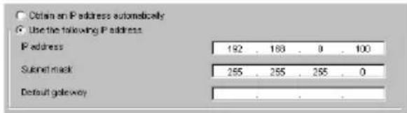
Vertical smear
A "smear" may appear to extend vertically from very bright subjects, as shown below.
This phenomenon is common to CCD imaging elements using an interline transfer system, and is caused when electric charge induced by infrared radiation deep within the photo sensor is transferred to the resistors.
AlIASING
When shooting fine stripes, straight lines or similar patterns, the lines may become slightly jagged.
Blemishes
A CCD image sensor consists of an array of individual picture elements (pixels). A malfunctioning sensor element will show up as a single pixel blemish in the image. This is generally not a problem.
White speckles
When you shoot a poorly illuminated object at a high temperature, small white dots may appear all over the entire screen image.
Supplied Accessories
When you unpack, check that all the supplied accessories are included.
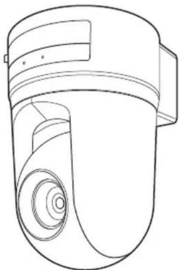
Camera (1)
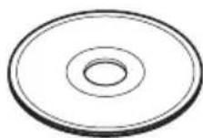
CD-ROM (including the Setup Program and User's Guide) (1)
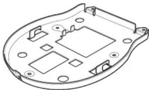
Ceiling bracket (A) (1)

Ceiling bracket (B) (1)
Wire rope (1)

Screws M3× 6 (6)

Installation Manual (this document) (1)
B&P Warranty Booklet (1)
(SNC-RZ25N only)
About the Supplied Manuals
Names of Manuals
The following manuals are supplied with this unit.
Installation Manual (this document)
The Installation Manual describes the names and functions of the parts of the camera, the installation and connections of the camera, etc. Be sure to read it before operating the camera.
User's Guide (stored in the CD-ROM)
The User's Guide describes the setup of the camera and the operations from the Web browser.
To open the User's Guide, see "Using the CD-ROM Manuals" below.
Using the CD-ROM Manuals
The supplied CD-ROM disc includes the User's Guides for the SNC-RZ25N/RZ25P (Japanese, English, French, German, Spanish, Italian and Chinese versions).
CD-ROM System Requirements
The following are required to access the supplied CD-ROM disc.
- Computer: PC with Intel Pentium CPU Installed memory: 64 MB or more CD-ROM drive: × 8 or faster
Monitor: Monitor supporting resolution of 1024× 768 or higher - OS: Microsoft Windows Millennium Edition, Windows 2000 Service Pack 2, Windows XP Professional or Home Edition
When these requirements are not met, access to the CD-ROM disc may be slow, or not possible at all.
Preparations
The Adobe Acrobat Reader Version 4.0 or later or the Adobe Reader Version 6.0 or later must be installed on your computer in order to use the User's Guide contained in the CD-ROM disc.
Note
If Adobe Acrobat Reader or Adobe Reader is not installed, it may be downloaded from the following URL:
http://www.adobe.com/products/acrobat/readstep2.html
Reading the manual in the CD-ROM
1 Insert the supplied CD-ROM into the CD-ROM drive.
After a short time a window will open displaying the files on the CD-ROM.
2 Double-click the PDF file of the SNC-RZ25N or SNC-RZ25P named "English."
The application will start, then the cover page of the User's Guide of the SNC-RZ25N or SNC-RZ25P is displayed. Clicking an item in the Table of Contents allows you jump to the relevant page.
Note
If you lose the CD-ROM disc or become unable to read its content, for example because of a hardware failure, contact a Sony service representative.
Location and Functions of Parts and Controls

Front
NETWORK indicator (orange/green)
The indicator flashes in orange when the camera is connected to the 10BASE-T network; it flashes in green when the camera is connected to the 100BASE-TX network.
The indicator goes off when the camera is not connected to the network.
CF card slot
Insert the wireless LAN card "SNCA-CFW1" especially designed to use with this camera or the storage (not supplied) into the slot.
And the SNCA-CFW1 can be attached with the optional antenna SNCA-AN1. It can expand the transmission area with the wireless LAN.
Note
Insert the CF card with its front side towards the NETWORK and POWER indicators.
CF card lever
Press the lever to remove the CF card from the CF card slot.
4 POWER indicator (green)
When the power is supplied to the camera, the camera starts checking the system. If the system is normal, this indicator lights up. If a system error occurs, this indicator flashes every second. In this case, consult your authorized Sony dealer.
5Lens
A × 18 optical zoom, auto-focus lens is mounted as standard equipment.

Rear
(network) port (RJ45)
Connect to the 10BASE-T or 100BASE-TX network using a network cable (UTP, category 5).
DC 12 V/AC 24 V (power input) terminal
Connect to a 12V DC or 24V AC power supply system.
(Video output) connector (BNC type)
Outputs a composite video signal. Connect to a composite video input connector of a video monitor, VCR, etc.
Reset switch
To reset the camera to the factory default settings, supply the power to the camera, while holding down this switch with a pointed object.
( microphone input) jack (minijack, monaural)
Connect a commercially available microphone. This jack supports plug-in power microphones (rated voltage: 2.4 V DC).
You can connect the microphones of the following specifications to this camera. Type: Electric condenser microphone Plug-in power system
Directivity: Nondirectional
Sensitivity: -40 ± 3.5 dB
Frequency range: 50 - 15,000Hz
(1) (line output) jack (minijack, monaural)
Connect a commercially available speaker system with the built-in amplifier.
You can connect the speakers of the following specifications to this camera.
Type: Active speaker
Impedance: Input impedance 4.7 kohms or more
Plug: 03.5 Mini-plug
I/O (Input/Output) port
This port is provided with an RS-232C port, two sensor inputs and two alarm outputs.
The RS-232C port is used when you connect peripheral devices to the camera using the RS-232C interface, and control the devices from the computer or transmit/receive data from the devices via the network.
The sensor input is used as the alarm input. The camera operation can be synchronized with E-mail or other applications.
The alarm output is used to control connected peripheral devices by synchronizing with an external sensor input, the built-in activity detection function, a manual trigger button, Day/ Night function or the timer function.
For details on each function and required settings, see the User's Guide stored in the supplied CD-ROM.
For pin assignment and wiring, see "Pin Assignment and Use of I/O Port" on page 28.
The I/O Port of this unit corresponds to the VISCA command. However, there are some commands which are not supported.

Tripod mounting hole
Use this hole to attach a commercially available tripod when attaching the camera to the tripod.
Ceiling bracket mounting screw holes
When installing the camera to the ceiling, secure the supplied ceiling brackets to these holes using the supplied screws.
Installing the Camera
Installing the Camera on the Ceiling
Using the supplied ceiling brackets, wire rope and screws, you can utilize existing junction boxes, etc., to attach the camera to the ceiling.
When you install the camera, always install it on a level ceiling. If you have to install it on a sloping or uneven ceiling, make sure that the place where you install it is within ± 15 degrees of the horizontal in order to ensure the pan/tilt mechanism functions properly.
Notes
- If you attach the camera to the ceiling, entrust the installation to an experienced contractor or installer.
- If you install the camera on the ceiling, ensure that the ceiling is strong enough to withstand the weight of the camera plus the ceiling brackets and then install the camera securely. If the ceiling is not strong enough, the camera may fall and cause serious injury.
- To prevent the camera from falling, make sure to attach the supplied wire rope.
- If you attach the camera to the ceiling, check periodically, at least once a year, to ensure that the connection has not loosened. If conditions warrant, make this periodic check more frequently.
Before installation
After deciding the direction in which the camera will shoot, make the required holes for the junction box, and connecting cables.
Note
The connecting cables cannot be passed through the ceiling bracket (A). A hole for the wiring is required in the ceiling at the back of the camera where it is attached to the ceiling.
Installation
1 Attach the wire rope to the junction box in the ceiling.
Use a screw hole and a screw (not supplied) in the junction box to attach the wirerope.

2 Attach the ceiling bracket (B) to the junction box on the ceiling.
Align the holes in the bracket with those in the junction box, and use appropriate screws (not supplied).
There are elongated holes for the screws along the rounded edges of the ceiling bracket (B). Later, the front of the camera will be positioned along this edge. Face the camera to the front, adjust the aim, and attach it securely.

Front of the camera
3 Attach the ceiling bracket (A) to the bottom of the camera using the supplied three screws ( M3× 6) supplied.
Align the screw holes on the bottom of the camera with those in the ceiling bracket, and attach the bracket to the camera.

Tighten the screws a bit at a time in the numbered order shown in the illustration. Attach the wire rope using the screw designated as number ③ above. After all of

the screws are temporarily tightened properly, securely tighten each one in turn.
Note
For assembly, use only the screws supplied with the camera. Using other screws may damage the camera.
4 Insert the protrusions raised on the ceiling bracket (A) into the spaces prepared in the ceiling bracket (B), and temporarily attach them by pushing the ceiling bracket (A) to the rear.

5 While pushing up on the front part of the camera, attach it using the supplied three screws ( M3× 6) starting with the screw at position 1.
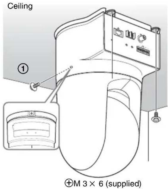
6 Connect the cables to the connectors on the rear of the camera.

Note
Take the proper steps to ensure that the load of the cables connected does not cause problems.
Removing the camera
1 Remove the three screws used to attach the camera in step 5 of "Installation."
2 While pushing the entire camera up towards the ceiling, move the camera to the front.
The hooks will disengage, and you can remove the camera.
Installing the Camera on a Flat Surface
Be sure to place the camera on a flat surface. If you must place the camera on an inclined surface, place it within ± 15 degrees of the horizontal in order to ensure the pan/tilt mechanism functions properly, and take countermeasure for preventing the camera from falling.

Notes
- Do not grasp the camera head when carrying the camera.
- Do not turn the camera head manually. Doing so will result in the camera malfunctioning.

To attach the camera to a tripod
Use a tripod with screws meeting either of the following specifications.

ISO standard: length 4.5mm± 0.2mm ASA standard: length 0.197 inches
Notes
- To attach a tripod, use the tripod mounting screw hole and attach the tripod firmly with a screwdriver.
- Install the tripod on a flat surface.
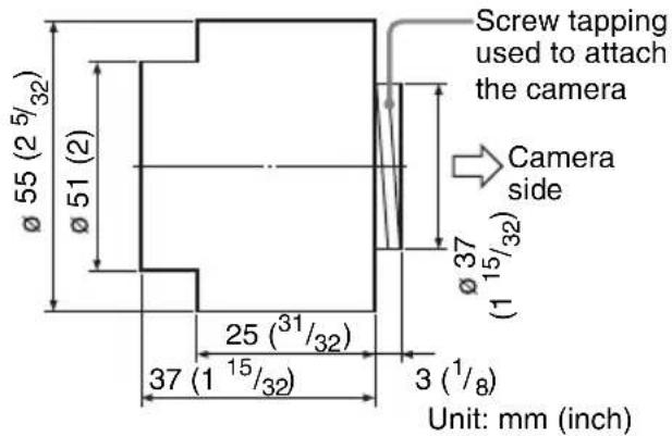
To attach a wide conversion lens
The camera's lens portion is threaded. To attach the conversion lens you use, align the lens with those threads, and turn it to the right to attach it securely.
Acceptable wide conversion lenses should weigh less than 100g (4 oz), and should not exceed the dimensions given in the illustration below.
Notes
In order to prevent the wide conversion lens from falling, follow the advice given below.
- Consult with an experienced contractor or installer to take countermeasure to ensure the wide conversion lens does not come loose and fall.
- Be sure that the lens is tightened securely, as far as it will go.
- Do not use a wide conversion lens in an environment where it is subject to vibration or shock.
- Check periodically, at least once a year, to ensure that the connection has not loosened. If conditions warrant, make this periodic check more frequently.
Connecting to a Computer or a Network
To connect to the computer, use a commercially available network cable (cross cable).
To connect to the network, use a commercially available network cable (straight cable).
System Requirements
Processor
Pentium III 1 GHz or higher (Pentium 4, 2
GHz or higher recommended)
RAM
256 MB or more
os
Windows 2000/ XP
Web browser
Internet Explorer Ver. 5.5 or Ver. 6.0
Connecting the Camera to a Computer
Using a commercially available network cable (cross), connect the network port on the camera on the network connector of a computer.

Connecting the Camera to a Local Network
Using a commercially available network cable, connect the network) port on the camera to a hub in the network.

Connecting Power
Two power supply systems are provided for the camera.
12VDC
- 24 V AC
Connect the 12 V DC or 24 V AC power supply system to the power input terminal on the rear of the Camera.

About the power source
Use the 12 V DC or 24 V AC power source isolated from the 100 to 240 V AC. The usable voltage range is as follows:
12 V DC: 10.8 to 13.2 V
24 V AC: 21.6 to 26.4 V
Use the UL cable (VW-1 style 1007) for 12 V DC or 24 V AC connection.
Recommended power cable
12VDC
| Cable (AWG) | #24 (0.22 mm) | #22 (0.33 mm) | #20 (0.52 mm) | #18 (0.83 mm) |
| Maximum cable length (m (feet)) | 4.5 (14.8) | 7.5 (24.6) | 12 (39) | 21 (69) |
24 V AC
| Cable (AWG) | #24 (0.22 mm) | #22 (0.33 mm) | #20 (0.52 mm) | #18 (0.83 mm) |
| Maximum cable length (m (feet)) | 10.5 (34) | 16.5 (54) | 27.5 (90) | 45.5 (149) |
Assigning the IP Address to the Camera
To connect the camera to a network, you need to assign a new IP address to the camera.
Before assigning the IP address, connect the camera to a computer or a network.
For details, see "Connecting to a Computer or a Network" (page 17).
You can assign the IP address in two ways:
- Using the setup program stored in the supplied CD-ROM
For details on the operations, see "Assigning the IP Address Using the Setup Program" on page 20.
- Using the ARP (Address Resolution Protocol) commands
Open the DOS window on the computer and enter the specified ARP commands.
For details on the operations, see "Assigning the IP Address to the Camera Using ARP Commands" in the User's Guide stored in the supplied CD-ROM.
Note
For determining the IP address to be assigned to the camera, consult your system administrator.
Assigning the IP Address Using the Setup Program
1 Insert the supplied CD-ROM disc into your CD-ROM drive.
After s short time a window will open displaying the files on the CD-ROM.
2 Click the Setup icon of IP Setup Program.
The File Download dialog opens.
3 Click Open.
Note
You cannot install the IP Setup Program properly if you click Save in the File Download dialog.
4 Install the IP Setup Program to your computer following the wizard displayed.
If "Software License Agreement" is displayed, read it carefully and accept the agreement to continue the installation.
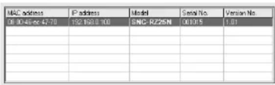
5 Start the IP Setup Program.
The program detects the SNC-RZ25N or SNC-RZ25P connected on the local
network and lists it (them) on the Network tab window.

6 Click the camera you want to assign a new IP address in the list.
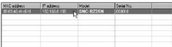
The network settings for the selected camera are displayed.
7 Set the IP address.
To obtain the IP address automatically from a DHCP server:
Select Obtain an IP address automatically.
Obtain an IP address automatically
Use the following IP address
The IP address, Subnet mask and Default gateway are assigned automatically.
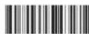
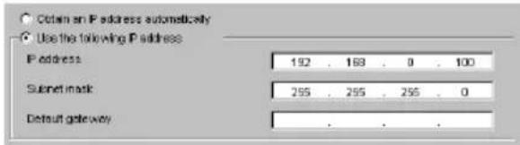
To specify the IP address manually:
Select Use the following IP address, and type the IP address, Subnet mask
and Default gateway in the relevant boxes.
8 Set the DNS server address.
To obtain the DNS server addresses automatically: Select Obtain DNS server address automatically.
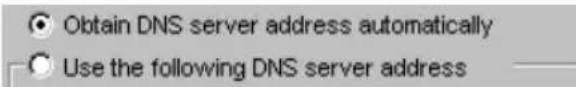
To specify the DNS server addresses manually:
Select Use the following DNS server address, and type the Primary DNS server address and Secondary DNS address in the relevant boxes.
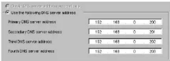
Note
The Third DNS server address and Fourth DNS server address are invalid for this camera.
9 Set the HTTP port number.

Normally select 80 for the HTTP port No. To use another port number, select the text box and type a port number between 1024 and 65535.
10Type the Administrator name and Administrator password.

The default settings of both items are "admin."
Note
You cannot change the Administrator name and Administrator password in this step. To change these items, see "Setting the User - User setting Page" of the User's Guide stored in the supplied CD-ROM.
11 Confirm that all items are correctly set, then click OK.

If "Setting OK" is displayed, the IP address is correctly assigned.
12To access the camera directly, double-click the camera name in the list.
The welcome page of the network camera SNC-RZ25N or SNC-RZ25P is displayed.

Note
If the IP address is not set correctly, the welcome page does not appear after step 12. In this case, try to set the IP address again.
Accessing the Camera Using the Web Browser
When the IP address has been assigned to the camera, check that you can actually access the camera using the Web browser installed in your computer.
This section explains how to access the camera using the Internet Explorer.
For details on the operations using the Web browser, i.e. for using a Web browser that is not the Internet Explorer, see the User's Guide stored in the supplied CD-ROM.
1 Start the Web browser on the computer and type the IP address of this camera in the URL box.
Example:
Address
http://192.168.0.100
The Welcome page is displayed.

2 Click Enter.
The main viewer is displayed.

When the main viewer is correctly displayed, the IP address assignment is completed.
When the main viewer of the camera is displayed for the first time
When you click Enter, "Security warning" is displayed.
When you click OK, the ActiveX control is installed and the main viewer is displayed.

Notes
-
If Automatic configuration is enabled in the Local Area Network (LAN) Settings on Internet Explorer, the image may not be displayed. In this case, disable Automatic configuration and set the Proxy server manually. For setting the Proxy server, consult your network administrator.
-
When you install ActiveX viewer on Windows 2000 or Windows XP, you should have logged in the computer as the Administrator.
Tip
Every page of this software is optimized as display character size Medium for Internet Explorer.
To display the Welcome page correctly
To operate the welcome page correctly, set the security level of the Internet Explorer to Medium or lower, as follows:
1 Select Tool from the menu bar for Internet Explorer, then select Internet Options and Security tab in sequence.
2 Click the Internet icon (when using the camera via the Internet) or Local intranet icon (when using the camera via a local network).
3 Set the slider to Medium or lower. (If the slider is not displayed, click Default Level.)
When using antivirus software in the computer
- When you use antivirus software in your computer, the camera performance may be reduced, for example, the frame rate for displaying the image may be lower.
- The Web page displayed when you log in the camera uses Java Script. The display of the Web page may be affected if you use antivirus software in your computer.
Specifications
Network
Protocol TCP/IP, ARP, ICMP, HTTP, FTP (server/client), SMTP (client), DHCP (client), DNS (client), NTP (client), SNMP (MIB-2), RTP/RTCP, PPPoE
Compression
Video compression format MPEG4/JPEG (selectable)
Audio compression format G.711/G726 (40,32,24,16 kbps)
Image size 640× 480 (VGA), 480× 360 384 × 288 320× 240 (QVGA)256 × 192 160× 120 (QQVGA)
Maximum frame rate SNC-RZ25N Max.30 FPS (QVGA)
SNC-RZ25P Max. 25 FPS (QVGA)
Web browser Internet Explorer Ver. 5.5 or 6.0
(Available OS: Windows 2000/XP)
Computer environments
CPU: Pentium III, 1 GHz or higher (Pentium 4, 2 GHz or higher recommended)
RAM: 256 MB or more
Display size: 1024 × 768
Maximum user access In JPEG mode: 20 users In MPEG4 mode: 10 users
Network security
Password (basic authentication), IP filtering
Homepage customization Starting from a homepage in the built-in flash memory or CF is possible.
Other functions Activity detection, image trimming, built-in clock, etc.
Camera
Video signal SNC-RZ25N:NTSC Color SNC-RZ25P:PAL Color
Picture element
1/4 inch color CCD
(Total picture elements:
SNC-RZ25N: Approx. 410,000
SNC-RZ25P: Approx. 470,000)
(Effective picture elements:
SNC-RZ25N: Approx. 380,000
SNC-RZ25P: Approx. 440,000)
Lens 18× (Optical), 12× (Digital) f = 4.1 to 73.8mm F1.4 to F3.0 Horizontal angle: 2.7irc to 48.0irc
Minimum object distance 30mm (13 / 16 inch):
Minimum illumination 0.7 lx (F1.4)/with 50 IRE
Shutter speed
1/1 to 1/10,000 s
Horizontal resolution NTSC:470 TV (WIDE end) PAL:460 TV (WIDE end)
Video S/N 50 dB
Mechanism
Pan -170irc to +170irc Maximum speed: 100irc / s Tilt -90irc to +30irc Maximum speed: 90irc / s
Interface
Network port 10BASE-T/100BASE-TX (RJ-45)
I/O port Sensor input: × 2 , make contact
Alarm output: × 2 , 24 V AC/DC, 1 A
(mechanical relay outputs electrically isolated from the camera)
Serial interface Transparency type RS-232C
Video outputVIDEO OUT:BNC,1.0 Vp-p, 75 ohms, unbalanced, sync negative
CF card slot Wirless card (802.11b) Memory card (storage)
Microphone input Sensitivity: -40± 3.5 dB Frequency range: 50 - 15,000Hz plug: φ 3.5mm (5/32 inches), Miniplug, plug-in power system
Line output Type: Active speaker
Input impedance: 4.7 kohms or more
plug: φ 3.5mm (5/32 inches), Miniplug
Others
Power supply 12VDC ± 10% 24VAC ± 10% , 50/60Hz
Power consumption 17 W max.
Operating temperature 0ircC to 40ircC (32°F to 104°F)
Storage temperature -20ircC to +60ircC (-4ircF to +140ircF)
Operating humidity 20 to 80%
Storage humidity 20 to 95%
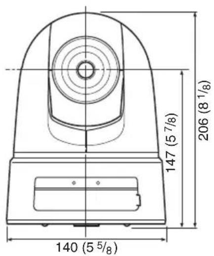
Dimensions 200× 140× 148mm (7 78× 558 × 57 / 8 inches) not including the projecting parts, lens and tripod adapter
Mass Approx. 1.3kg (2 lb 14 oz)
Supplied accessories CD-ROM (setup program and User's Guide) (1) Ceiling bracket A1Ceiling bracket B1 Wire rope 1 Screws M3× 6 6 Installation Manual this document)1 B&P Warranty Booklet (1) SNCRZ25N only
Optional accessories
Wirless card SNCA-CFW1
Antenna for wireless card SNCA-AN1
Memory stick Duo adapter corresponding to compact flash TM slot
MSAC-MCF1
Memory stick Duo MSX-M512S (512MB)
Design and specifications are subject to change without notice.
Regular parts replacement
Some of the parts that make up this product (electrolytic condenser, for example) need replacing regularly depending on their life expectancies. The lives of parts differ according to the environment or condition in which this product is used and the length of time it is used, so we recommend regular checks. Consult the dealer from whom you bought it for details.
Front
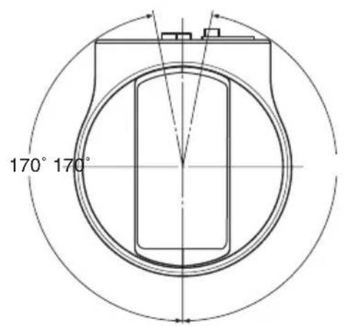
Top
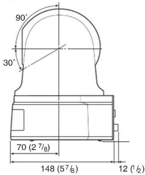
Side

Bottom
Unit: mm (inches)

Front

Side
Ceiling bracket (B)

Unit: mm (inches)

Pin Assignment and Use of I/O Port
Pin assignment of I/O port

| Pin No. | Pin name |
| 1 Sensor In 1 + | |
| 2 Sensor In 1- (GND) | |
| 3 Sensor In 2 + | |
| 4 Sensor In 2- (GND) | |
| 5 Alarm Out 1 + | |
| 6 Alarm Out 1 - | |
| 7 Alarm Out 2 + | |
| 8 Alarm Out 2 - | |
| 9 GND | |
| 10 GND | |
| 11 RS232C · RX | |
| 12 RS232C · TX | |
Using the I/O receptacle
While holding down the button on the slot to which you want to connect the wire (AWG No. 28 to 22) with a small slotted screwdriver, insert the wire into the slot. Then release the screwdriver from the button.

1
2
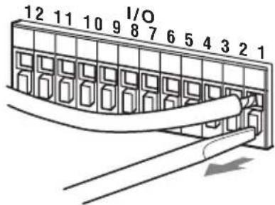
Repeat this procedure to connect all required wires.
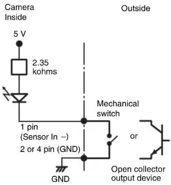
Wiring diagram for sensor input Mechanical switch/open collector output device
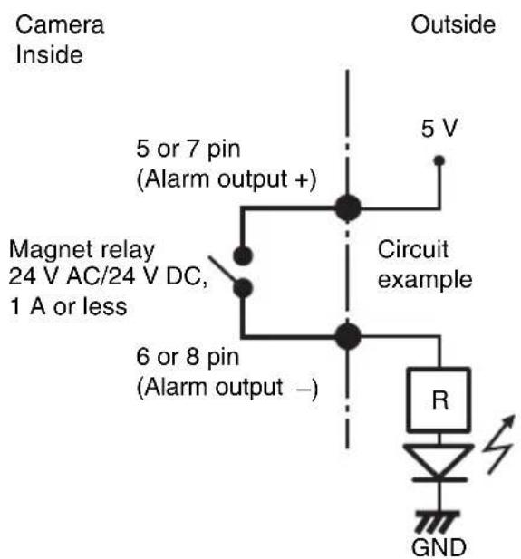
Wiring diagram for alarm output
AVENTISSEMENT
Alimentation a raccorder 19
Obtain an IP address automatically

Use the following IP address
Obtain DNS server address automatically

Use the following DNS server address:
Protocole TCP/IP, ARP, ICMP, HTTP, FTP (serveur/client), SMTP (client), DHCP (client), DNS (client), NTP (client), SNMP (MIB-2), RTP/RTCP, PPPoE
Compression
Carte memoire (stockage)
Entree de micro
24 V CA ± 10%, 50/60 Hz
Puissance consommée
17 W max.
http://www.adobe.com/products/acrobat/readstep2.html
Puerto (Red) (RJ45)
Selezione Obtain an IP address automatically.
Obtain an IP address automatically
C Use the following IP address
Se asignará automatístico IP address, Subnet mask y Default gateway.
Obtain DNS server address automatically
C Use the following DNS server address
| MAC address | IP address | Model | Serial No. | Version No. |
| 08 00:48:cc:47:70 | 152.152.0.100 | SNC-R226N | 001015 | 1.01 |
Se做不到 a网页 of bienvenida de la camarada de red SNC-RZ25N o SNC-RZ25P.

Nota

- 安全のたてに
- ARP (Address Resolution)
- Protocol) ペマンドを使う
- 固定 IP トレスを設定するとは
- DNS サーパーダレスを設定する。
- 压缩方式
- WARNING
- WARNING (for Installers only)
- CAUTION
- CAUTION for LAN port
- Power Supply
- Caution for other countries
- For customers in the U.S.A. (SNC-RZ25N only)
- For customers in Canada (SNC-RZ25N only)
- For customers in other countries
- ATTENTION
- Table of Contents
- Overview
- Basic Installation and Connections
- Others
- Features
- High-quality monitoring via the network
- Available Web browsers
- Remote-controllable high-speed pan/tilt mechanism and high magnification auto-focus zoom lens
- Wireless LAN
- Image transmission using an E-mail or FTP server
- Preset positions and Tour programs
- Alarm output
- Direct panning/tilting
- Precautions
- Heed the safety precautions
- In case of a breakdown
- In case of abnormal operation
- Operating Precautions
- Operating or storage location
- Ventilation
- Transportation
- Cleaning
- Note on laser beams
- NOTICE TO USERS
- INFORMATION CONTAINED HEREIN OR THE USE THEREOF.
- Typical CCD Phenomena
- Vertical smear
- AlIASING
- Blemishes
- White speckles
- Supplied Accessories
- About the Supplied Manuals
- Names of Manuals
- Installation Manual (this document)
- User's Guide (stored in the CD-ROM)
- Using the CD-ROM Manuals
- CD-ROM System Requirements
- Preparations
- Note
- Reading the manual in the CD-ROM
- Location and Functions of Parts and Controls
- NETWORK indicator (orange/green)
- CF card slot
- CF card lever
- POWER indicator (green)
- 5Lens
- (network) port (RJ45)
- DC 12 V/AC 24 V (power input) terminal
- (Video output) connector (BNC type)
- Reset switch
- ( microphone input) jack (minijack, monaural)
- (line output) jack (minijack, monaural)
- I/O (Input/Output) port
- Tripod mounting hole
- Ceiling bracket mounting screw holes
- Installing the Camera
- Installing the Camera on the Ceiling
- Notes
- Before installation
- Installation
- Removing the camera
- Installing the Camera on a Flat Surface
- To attach the camera to a tripod
- To attach a wide conversion lens
- Connecting to a Computer or a Network
- System Requirements
- Processor
- RAM
- os
- Web browser
- Connecting the Camera to a Computer
- Connecting the Camera to a Local Network
- Connecting Power
- About the power source
- Recommended power cable
- Assigning the IP Address to the Camera
- Assigning the IP Address Using the Setup Program
- Click the camera you want to assign a new IP address in the list.
- Set the IP address.
- To specify the IP address manually:
- Set the DNS server address.
- To specify the DNS server addresses manually:
- Set the HTTP port number.
- 10Type the Administrator name and Administrator password.
- Confirm that all items are correctly set, then click OK.
- 12To access the camera directly, double-click the camera name in the list.
- Accessing the Camera Using the Web Browser
- Start the Web browser on the computer and type the IP address of this camera in the URL box.
- Click Enter.
- When the main viewer of the camera is displayed for the first time
- Tip
- To display the Welcome page correctly
- When using antivirus software in the computer
- Specifications
- Network
- Compression
- Camera
- Mechanism
- Interface
- Optional accessories
- Regular parts replacement
- Pin Assignment and Use of I/O Port
- Pin assignment of I/O port
- Using the I/O receptacle
- Wiring diagram for sensor input Mechanical switch/open collector output device
- Wiring diagram for alarm output
- AVENTISSEMENT
- Puerto (Red) (RJ45)
- Nota
Brand : SONY
Model : SNCRZ25N
Category : Surveillance Camera