
SNCRZ50N - Surveillance Camera SONY - Free user manual and instructions
Find the device manual for free SNCRZ50N SONY in PDF.
| Product Type | Network Surveillance Camera |
| Brand | Sony |
| Model | SNCRZ50N |
| Signal System | NTSC (N model), PAL (P model) |
| Imaging Device | 1/4-inch color CCD |
| Effective Picture Elements | 340,000 (N), 400,000 (P) |
| Lens | Autofocus zoom, f=3.5 to 91 mm, F1.6 to F3.8 |
| Optical Zoom | 26x |
| Digital Zoom | 12x |
| Horizontal Resolution | 450 TV lines (WIDE side) |
| Minimum Illumination | 2.2 lx (F1.6/50 IRE) |
| Shutter Speed | 1 to 1/10,000 s |
| Pan Angle | -170° to +170° |
| Tilt Angle | -90° to +25° |
| Pan/Tilt Speed | 300°/s max. |
| Video Compression | JPEG, MPEG4, H.264 |
| Max. Number of Simultaneous Users | 20 |
| Network Interface | 10BASE-T/100BASE-TX (RJ-45) |
| I/O Ports | 2 sensor inputs, 2 alarm outputs, RS-232C |
| Power Supply | 12 V DC ±10% (AC adapter included) |
| Power Consumption | 20 W max. |
| Operating Temperature | 0 °C to +40 °C |
| Dimensions (H/W/D) | 166 × 140 × 142 mm |
| Weight | Approx. 1.2 kg |
| Supplied Accessories | AC adapter, CD-ROM, ceiling mounts, metal cable, etc. |
| Maintenance and Cleaning | Use a dry soft cloth. Do not use solvents. |
| Security | Password, IP filtering |
| Replaceable Parts | Electrolytic capacitor (regular check recommended) |
Frequently Asked Questions - SNCRZ50N SONY
User questions about SNCRZ50N SONY
0 question about this device. Answer the ones you know or ask your own.
Ask a new question about this device
Download the instructions for your Surveillance Camera in PDF format for free! Find your manual SNCRZ50N - SONY and take your electronic device back in hand. On this page are published all the documents necessary for the use of your device. SNCRZ50N by SONY.
USER MANUAL SNCRZ50N SONY
Printed on 100% recycled paper.
お問い合わせ
© 2005 Sony Corporation
3990920020
安全のために
natural_image
Technical line drawing of a mechanical component with no visible text or symbolsnatural_image
Line drawing of a rectangular electronic device with a coiled cable and two ports, no text or symbols present.電源コード(1)
natural_image
Line drawing of a cord with two plug plugs (no text or symbols)シーリングブラケット (下) (1)
natural_image
Technical line drawing of a mechanical component with holes and mounting holes (no text or symbols)シーリングブラケット (上) (1)

natural_image
Technical line drawing of a mechanical component with symmetrical slots and central hole (no text or symbols)落下防止用ワイヤーロープ(1)

natural_image
Simple line drawing of a coiled cable or wire with two terminal ends (no text or symbols)ケーブルカバー (1)

natural_image
Line drawing of a 3D rectangular box with rounded corners and a small protrusion on the side (no text or symbols)マウントカバー(1)

natural_image
Line drawing of a curved mechanical component or bracket (no text or symbols)取り付け用ネジ ⊕M3 ×6 (9)

段付きネジ ⊕M4(1)

プラグ押さえ(1)

natural_image
Simple line drawing of a bent metal bracket with a circular hole (no text or symbols)ゴム足(4)
natural_image
Simple geometric diagram of four circles arranged in a 2x2 grid within a parallelogram (no text or symbols)保証書(冊子)(1)
保証シート (1)
設置説明書(本書)(1)
付属の説明書について
説明書の種類
text_image
CLASS 2 WIRING SLC INSTRUCTION MANUAL LAN 10 9 8 7 6 5 4 3 2 1⑧DC IN 12V(電源入力)端子
text_image
Technical diagram of a device rear panel with numbered component labels⑮三脚取り付け用ネジ穴
text_image
1/4-20UNC ℓ = 4.5mm ± 0.2mmご注意
text_image
Diagram illustrating hand press application on a device, showing two states of press with X marks and directional arrows.天井に設置する
natural_image
Technical line drawing of a mechanical device with attached wiring and housing (no text or symbols)natural_image
Pure technical line drawing of a 3D mechanical part with no text, numbers, or symbolsnatural_image
Technical line drawing of a mechanical component with mounting holes and internal features (no text or symbols)natural_image
Line drawing of a mechanical component with concentric circular features (no text or symbols)ご注意
• ARP (Address Resolution
Protocol) コマンドを使う
コンピューターでコマンドプロンプト
text_image
IP Setup Program ver1.3.5 Networks | Bandwidth control | Data line | BPSF MAC address | IP address | Model | Serial No | Version No. 00.01.44-cd-77-88 | 192.168.0.100 | SNC-F250N | 001.015 | 1.00 | Obtain an P address automatically Use the following P address Primary DNS server address Secondary DNS server address Third DNS server address Focus DNS server address Obtain DNS server address automatically Use the following DNS server address Primary DNS server address Secondary DNS server address Third DNS server address Focus DNS server address HTTP port No. 60 (1.024 to 65535) Administrator name: Administrator password: Finish Cancel OK| MAC address | IP address | Model | Serial No. | Version No. |
| 00:01-4e-cd-77-b8 | 192168.0.100 | SNC P25CN | 001015 | 1.00 |
Obtain an IP address automatically
Use the following IP address
text_image
Obtain an IP address automatically Use the following IP address IP address 102 . 168 . 0 . 100 Subnet mask 255 . 0 . 0 . 0 Default gateway . . . .ご注意
- Obtain DNS server address automatically - Use the following DNS server address
text_image
Use the following DNS server address Primary DNS server address 192 . 168 . 0 . 200 Secondary DNS server address 192 . 168 . 0 . 201 Third DNS server address Fourth DNS server addressご注意
text_image
Administrator name: admin Administrator password: newtext_image
Information Setting OK OK| MAC address | IP address | Model | Serial No. | Version No. |
| 09-01-4e-cd-77-b8 | 152.168.0.100 | 5NC-F250N | 001015 | 1.00 |
補足
text_image
IPELA Network Camera SNC-RZ50N Enter MPDDR ● Active sensor JNDG ● Active sensor ● Active sensor Setting SPEG - 120000 SONY Copyright © 2008 Sony Corporation. All rights reserved.ご注意
G.711/G.726 (40, 32, 24,
16 kbps)
映像出力サイズ
$$ 6 4 0 \times 4 8 0 (\mathrm{VGA}), $$
$$ 3 2 0 \times 2 4 0 (\mathrm{QVGA}), $$
$$ 1 6 0 \times 1 2 0 (\text {QQVGA}) $$
最大フレームレート
SNC-RZ50N : 30 fps
SNC-RZ50P : 25 fps
Web ブラウザ
2.2 lx (F1.6/50 IRE)
シャッタースピード
1 \~ 1/10,000 秒
natural_image
Technical line drawing of a vehicle dashboard with control panel and rear-mounted sensors (no text or symbols)The model and serial numbers are located on the bottom. Record these numbers in the spaces provided below.
Refer to these numbers whenever you call upon your Sony dealer regarding this product.
Model No. Serial No.
WARNING
To reduce a risk of fire or electric shock, do not expose this product to rain or moisture.
To avoid electrical shock, do not open the cabinet. Refer servicing to qualified personnel only.
AC power adaptor
Model No.: MPA-AC1 (Sony)
CAUTION: This unit is for use only with the supplied AC power adaptor. Use with other AC power adaptors may cause hazards such as a fire.
WARNING
This installation should be made by a qualified service person and should conform to all local codes.
WARNING
A readily accessible disconnect device shall be incorporated in the building installation wiring.
WARNING (for Installers only)
Instructions for installing the equipment on the ceiling:
After the installation, ensure the connection is capable of supporting five times the weight of the equipment downwards.
CAUTION
The rating label is located on the bottom.
CAUTION for LAN port
For safety reason, do not connect the LAN port to any network devices that might have excessive voltage.
For customers in the U.S.A. (SNC-RZ50N only)
This device complies with Part 15 of the FCC Rules. Operation is subject to the following two conditions: (1) This device may not cause harmful interference, and (2) this device must accept any interference received, including interference that may cause undesired operation.
NOTE: This equipment has been tested and found to comply with the limits for a Class A digital device, pursuant to part 15 of the FCC Rules. These limits are designed to provide reasonable protection against harmful interference when the equipment is operated in a commercial environment. This equipment generates, uses, and can radiate radio frequency energy and, if not installed and used in accordance with the instruction manual, may cause harmful interference to radio communications. Operation of this equipment in a residential area is likely to cause harmful interference in which case the user will be required to correct the interference at his own expense.
CAUTION
You are cautioned that any changes or modifications not expressly approved in this manual could void your authority to operate this equipment.
All interface cables used to connect peripherals must be shielded in order to comply with the limits for a digital device pursuant to Subpart B or Part 15 of FCC Rules.
For customers in Canada (SNC-RZ50N only)
This Class A digital apparatus complies with Canadian ICES-003.
For customers in other countries
WARNING
This is a Class A product. In a domestic environment, this product may cause radio interference in which case the user may be required to take adequate measures. In the case that interference should occur, consult your nearest authorized Sony service facility.
ATTENTION
The electromagnetic fields at specific frequencies may influence the picture of the unit.
For the customers in Netherlands
Operating Precautions ....5
Typical CCD Phenomena .....7
Supplied Accessories ....7
About the Supplied Manuals ......9
Names of Manuals ......9
Using the CD-ROM Manuals .....9
Location and Functions of Parts and Controls ....10
Basic Installation and Connections
Installing the Camera ....14
Installing the Camera on the Ceiling ....14
Installing the Camera on the Desk Top ....19
Connecting to a Computer or a Network ....20
System Requirements ....20
Connecting the Camera to a Computer ....20
Connecting the Camera to a Local Network ....21
Connecting Power ......21
Assigning the IP Address to the Camera 22
Assigning the IP Address Using the Setup Program ....23
Accessing the Camera Using the Web Browser ....25
Others
Specifications 27
Dimensions 29
Pin Assignment and Use of I/O Port 31
When You Discard the Camera ..... 32
Features
High-quality monitoring via the network
You can monitor a high-quality live image from the camera using the Web browser on a computer connected to a 10BASE-T or 100BASE-TX network. The maximum frame rate is 30 fps for SNC-RZ50N and 25 fps for SNC-RZ50P.
Up to 20 users can view the image from one camera at the same time.
The camera supports JPEG, MPEG4 and H.264 video compression (video codecs) and can operate in either the “Single codec” or “Dual codec” mode. The “Single codec” mode allows monitoring one of the two video codecs, and the “Dual codec” mode allows monitoring in JPEG and MPEG4 simultaneously.
Remote-controllable high-speed pan/tilt mechanism and high magnification auto-focus zoom lens
The camera is provided with a high-speed (300° rotation/second) pan/tilt mechanism, which allows -170° to +170° panning and -90° to +25° tilting. The camera is also provided with a high-magnification zoom lens with optical zoom of 26 magnifications and digital zoom of 12 magnifications, for a total of 312 magnifications.
Wireless LAN
Inserting the optional SNCA-CFW1 wireless card into the CF card slot or PC card slot enables you to transmit images from the camera via wireless LAN (802.11b). If you use the CF card slot, insert the Sony wireless card SNCA-CFW1 (optional) in it. If you use the PC card slot, use with a commercially available Compact Flash Type II-PCMCIA converting adaptor.
Image transmission using an e-mail or FTP
You can send a still image from the camera as an attachment of an e-mail or to an FTP server, by setting off a trigger using an
external sensor input, built-in object detection function or manual trigger button occurs. You can also send still images sequentially for a determined period before and after the trigger to an FTP server, or send them periodically.
Preset positions and Tour programs
You can save up to 16 preset positions (pan, tilt and zoom positions) of the camera, and up to 5 tour programs composed from the preset positions. You can activate the preset positions by synchronizing them with an external sensor input or built-in detection function.
Intelligent object detection function
The camera is provided an intelligent object detection function to watch images. This function combines “Moving object detection” that detects moving objects in camera images with “Unattended object detection” that detects objects that do not move for a specified period in camera images.
Alarm output
The camera is equipped with two sets of alarm outputs. You can use the alarms to control peripheral devices by synchronizing them with the external sensor inputs, built-in detection function, manual trigger button, Day/Night function or timer.
Direct panning/tilting
Clicking on a desired point in the viewer allows you to pan and tilt the camera in the direction of that point. Dragging a desired area in the viewer allows you to zoom in the dragged area as well as pan and tilt the camera.
Superimpose function
Date/time can be superimposed on the image. You can select the superimposing point from among four corners of the display, and you have the option to write time data and four-figure camera ID into it.
Precautions
This Sony product has been designed with safety in mind. However, if not used properly electrical products can cause fires which may lead to serious body injury. To avoid such accidents, be sure to heed the following.
Heed the safety precautions
Be sure to follow the general safety precautions, and the “Operating Precautions.”
In case of a breakdown
In case of a system breakdown, discontinue use and contact your authorized Sony dealer.
In case of abnormal operation
- If the unit emits smoke or an unusual smell,
- If water or other foreign objects enter the cabinet, or
- If you drop the unit or damage the cabinet:
1 Disconnect the camera cable and the connecting cables.
2 Contact your authorized Sony dealer or the store where you purchased the product.
Operating Precautions
Operating or storage location
Avoid operating or storing the camera in the following locations:
- Extremely hot or cold places (Operating temperature: 0^ to +40^ [32°F to 104°F])
- Exposed to direct sunlight for a long time, or close to heating equipment (e.g., near heaters)
- Close to sources of strong magnetism
- Close to sources of powerful electromagnetic radiation, such as radios or TV transmitters
- Locations subject to strong vibration or shock
Ventilation
To prevent heat buildup, do not block air circulation around the camera.
Transportation
When transporting the camera, repack it as originally packed at the factory or in materials of equal quality.
Cleaning
- Use a blower to remove dust from the lens or optical filter.
- Use a soft, dry cloth to clean the external surfaces of the camera. Stubborn stains can be removed using a soft cloth dampened with a small quantity of detergent solution, then wipe dry.
- Do not use volatile solvents such as alcohol, benzene or thinners as they may damage the surface finishes.
Note on laser beams
Laser beams may damage the CCDs. If you shoot a scene that includes a laser beam, be careful not to let a laser beam become directed into the CCDs of the camera.
- You should keep in mind that the images or audio you are monitoring may be protected by privacy and other legal rights, and the responsibility for making sure you are complying with applicable laws is yours alone.
- Access to the images and audio is protected only by a user name and the password you set up. No further authentication is provided nor should you presume that any other protective filtering is done by the service. Since the service is Internet-based, there is a risk that the image or audio you are monitoring can be viewed or used by a third-party via the network.
- SONY IS NOT RESPONSIBLE, AND ASSUMES ABSOLUTELY NO LIABILITY TO YOU OR ANYONE ELSE, FOR SERVICE INTERRUPTIONS OR DISCONTINUATIONS OR EVEN SERVICE CANCELLATION. THE SERVICE IS PROVIDED AS-IS, AND SONY DISCLAIMS AND EXCLUDES ALL WARRANTIES, EXPRESS OR IMPLIED, WITH RESPECT TO THE SERVICE INCLUDING, BUT NOT LIMITED TO, ANY OR ALL IMPLIED WARRANTIES OF MERCHANTABILITY, FITNESS FOR A PARTICULAR PURPOSE, OR THAT IT WILL OPERATE ERROR-FREE OR CONTINUOUSLY.
NOTICE TO USERS
© 2005 Sony Corporation. All rights reserved. This manual or the software described herein, in whole or in part, may not be reproduced, translated or reduced to any machine readable form without prior written approval from Sony Corporation.
SONY CORPORATION PROVIDES NO WARRANTY WITH REGARD TO THIS MANUAL, THE SOFTWARE OR OTHER INFORMATION CONTAINED HEREIN AND HEREBY EXPRESSLY DISCLAIMS ANY IMPLIED WARRANTIES OF MERCHANTABILITY OR FITNESS FOR
ANY PARTICULAR PURPOSE WITH REGARD TO THIS MANUAL, THE SOFTWARE OR SUCH OTHER INFORMATION. IN NO EVENT SHALL SONY CORPORATION BE LIABLE FOR ANY INCIDENTAL, CONSEQUENTIAL OR SPECIAL DAMAGES, WHETHER BASED ON TORT, CONTRACT, OR OTHERWISE, ARISING OUT OF OR IN CONNECTION WITH THIS MANUAL, THE SOFTWARE OR OTHER INFORMATION CONTAINED HEREIN OR THE USE THEREOF.
Sony Corporation reserves the right to make any modification to this manual or the information contained herein at any time without notice.
The software described herein may also be governed by the terms of a separate user license agreement.
- “IPELA” and are trademarks of Sony Corporation.
- “VISCA” is a trademark of Sony Corporation.
- Microsoft, Windows, Internet Explorer and MS-DOS are registered trademarks of Microsoft Corporation in the United States and/or other countries.
- Java is a trademark of Sun Microsystems, Inc. in the United States and other countries.
- Intel and Pentium are registered trademarks of Intel Corporation or its subsidiaries in the United States and other countries.
- Adobe, Acrobat and Adobe Reader are trademarks of Adobe Systems Incorporated in the United States and/or other countries.
- CompactFlash and CF are trademarks of SanDisk Corporation, registered in the United States and other countries.
All other company and product names are trademarks or registered trademarks of the respective companies or their respective makers.
Typical CCD Phenomena
The following phenomena may appear on the monitor screen while you are using a CCD ^* color video camera. These phenomena stem from the high sensitivity of the CCD image sensors, and do not indicate a fault within the camera.
Vertical smear
A “smear” may appear to extend vertically from very bright subjects, as shown below.

text_image
Video monitor screen Pale vertical smear Very bright subject (such as an electric lamp, fluorescent lamp, sunlight, or strong reflected light)This phenomenon is common to CCD imaging elements using an interline transfer system, and is caused when electric charge induced by infrared radiation deep within the photo sensor is transferred to the resistors.
Aliasing
When shooting fine stripes, straight lines or similar patterns, the lines may become slightly jagged.
Blemishes
A CCD image sensor consists of an array of individual picture elements (pixels). A malfunctioning sensor element will show up as a single pixel blemish in the image. This is generally not a problem.
White speckles
When you shoot a poorly illuminated object at a high temperature, small white dots may appear all over the entire screen image.
Supplied Accessories
When you unpack, check that all the supplied accessories are included.
Camera (1)

natural_image
Technical line drawing of a mechanical component with no visible text or symbolsAC power adaptor (1)

natural_image
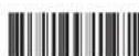
Line drawing of a rectangular electronic device with a coiled cable and connector (no text or symbols)AC power cord (1)
USA and Canadian model

natural_image
Line drawing of a cord with two connected power plugs (no text or symbols)European model

natural_image
Line drawing of a cable with a plug and terminal outlet (no text or symbols)CD-ROM (including the User's Guide and supplied programs) (1)

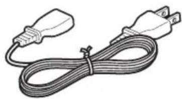
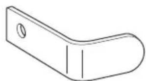
Lower ceiling bracket (1)

natural_image
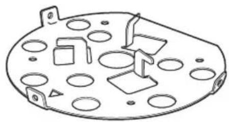
Technical line drawing of a mechanical component with holes and mounting brackets (no text or symbols)Upper ceiling bracket (1)

natural_image
Technical line drawing of a mechanical component with cutouts and mounting holes (no text or symbols)Fall-prevention wire rope (1)

natural_image
Simple line drawing of a coiled cable or wire with two connectors (no text or symbols)Cable cover (1)

natural_image
Line drawing of a rectangular container or housing with a small protrusion on the side (no text or symbols)Mounting bracket cover (1)

natural_image
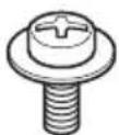
Line drawing of a curved mechanical component or bracket (no text or symbols)Screws ⊕M3 × 6 (9)

Shoulder screw ⊕M4 (1)

Plug retainer (1)

natural_image
Simple line drawing of a bent metal bracket with a circular hole (no text or symbols)Rubber foot (4)

natural_image
Simple geometric diagram of four circles arranged in a 2x2 grid within a parallelogram (no text or symbols)Installation Manual (this document) (1)
B&P Warranty Booklet (1) (SNC-RZ50N only)
About the Supplied Manuals
Names of Manuals
The following manuals are supplied with this unit.
Installation Manual (this document)
The Installation Manual describes the names and functions of the parts of the camera, the installation and connections of the camera, etc. Be sure to read it before operating the camera.
User's Guide (stored in the CD-ROM)
The User's Guide describes the setup of the camera and the operations from the Web browser.
To open the User's Guide, see "Using the CD-ROM Manuals" below.
Using the CD-ROM Manuals
The supplied CD-ROM disc includes the User's Guides for this unit (Japanese, English, French, German, Spanish, Italian and Chinese versions) in PDF format.
Preparations
The Adobe Reader Version 6.0 or higher must be installed on your computer in order to use the User's Guide stored in the CD-ROM disc.
Note
If Adobe Reader is not installed, it may be downloaded from the following URL: http://www.adobe.com/
Reading the manual in the CD-ROM
1 Insert the CD-ROM in your CD-ROM drive.
A cover page appears automatically in your Web browser.
If it does not appear automatically in the Web browser, double-click on the index.htm file on the CD-ROM.
2 Select and click on the manual that you want to read.
This opens the PDF file of the manual. Clicking an item in the Table of Contents allows you jump to the relevant page.
Notes
- The files may not be displayed properly, depending on the version of Adobe Reader. In this case, install the latest version, which you can download from the URL mentioned in “Preparations” above.
- If you have lost or damaged the CD-ROM, you can purchase replacement. Contact your Sony service representative.
Location and Functions of Parts and Controls
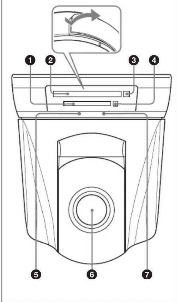
Front
text_image
Technical diagram of a car air conditioner unit with numbered parts and an inset showing airflow direction①CF card slot
Insert the optional SNCA-CFW1 wireless card especially designed to use with this camera or the recommended CF memory card into the slot. And the SNCA-CFW1 can be attached with the optional SNCA-AN1 wireless LAN antenna. It can expand the transmission area with the wireless LAN.
Notes
- Insert the CF memory card with its front side towards the NETWORK indicator.
- For the verified CF memory cards, contact your authorized Sony dealer.
②PC card slot
This slot is used for the optional SNCA-CFW1 wireless card or recommended ATA memory card.
In case of the wireless card: Insert the SNCA-CFW1 into a commercially available type II-PCMCIA adaptor and insert the adaptor into the PC card slot. A wider wireless LAN area is available if you attach the optional SNCA-AN1 wireless LAN antenna to the SNCA-CFW1.
Notes
- Insert the PC card with its front side towards the bottom of the camera.
- For the verified ATA memory cards, contact your authorized Sony dealer.
③PC card lever
Press the lever to remove the PC card from the PC card slot.
④CF card lever
Press the lever to remove the CF memory card from the CF card slot.
⑤NETWORK indicator (green)
The indicator lights up or flashes in green when the camera is connected to the network.
The indicator goes off when the camera is not connected to the network.
6 Lens
A × 26 optical zoom, auto-focus lens is mounted as standard equipment.
⑦ POWER indicator (green)
When the power is supplied to the camera, the camera starts checking the system.
If the system works normally, this indicator lights up.
If a system error occurs, this indicator flashes every second. In this case, consult your authorized Sony dealer.
Rear

text_image
CLASS 2 WIRING SEE INSTRUCTION MANUAL DC B 1kV LAN 10 11 12 13 14⑧DC IN 12 V (power input) connector
Connect the supplied AC power adaptor.
9 → (video output) connector (BNC type)
Outputs a composite video signal. Connect to a composite video input connector of a video monitor, etc.
10LAN (network) port (RJ45)
Connect to the 10BASE-T or 100BASE-TX network using a network cable (UTP, category 5).
(11) (microphone input) jack (minijack, monaural)
Connect a commercially available microphone. This jack supports plug-in-power microphones (rated voltage: 2.5 V DC).
You can connect the microphones of the following specifications to this camera.
Type: Electret condenser microphone Plug-in power system
Directivity: Omni-directional
Sensitivity: -40 ± 3.5 dB
Frequency range: 50 – 15,000 Hz
Plug: ∅3.5 Mini-plug
12 (line output) jack (minijack, monaural)
Connect a commercially available speaker system with the built-in amplifier.
You can connect the speakers of the following specifications to this camera.
Type: Active speaker
Impedance: Input impedance 4.7 kohms or more
Plug: ∅3.5 Mini-plug
⑬I/O (Input/Output) port
This port is provided with an RS-232C port, two sensor inputs and two alarm outputs.
The RS-232C port is used when you connect peripheral devices to the camera using the RS-232C interface, and control the camera or transmit/receive data from the devices.
The sensor input is used as the alarm input. The camera operation can be synchronized with e-mail (SMTP) or other applications.
The alarm output is used to control connected peripheral devices by synchronizing with an external sensor input, the built-in detection function, a manual trigger button, Day/Night function or the timer function.
For pin assignment and wiring, see "Pin Assignment and Use of I/O Port" on page 31.
Note
The I/O port of this unit corresponds to the VISCA command. However, there are some commands which are not supported.
14 Reset switch
To reset the camera to the factory default settings, supply the power to the camera, while holding down this switch with a pointed object.
For details on each function and required settings, see the User's Guide stored in the supplied CD-ROM.
Bottom

text_image
Technical diagram of a device rear panel with numbered component labels⑮Tripod hole
Use this hole when attaching the camera to a tripod (screw: 1/4", 20 UNC)

U1/4", 20 UNC
= 4.5 ~mm ± 0.2 ~mm
(ISO standard)
Caution
Use the mounting screw whose length is 4.5 mm ± 0.2 mm only. Use of other screws may cause improper mounting and damage parts inside the camera.
⑯Ceiling bracket mounting screw holes
When installing the camera on the ceiling, fix the supplied ceiling brackets to these holes using the supplied screws ( M3 × 6 ).
⑰Screw hole for fall-prevention wire rope
When installing the camera on the ceiling, fix the supplied fall-prevention wire rope to this hole using the supplied shoulder screw ( M4).
For installation on the ceiling, see "Installing the Camera on the Ceiling" on page 14.
Installing the Camera
Notes
- Do not grasp the camera head when carrying the camera.
- Do not turn the camera head manually. Doing so will result in the camera malfunctioning.

natural_image
Line drawing of a hand holding a device with a cross mark above, no text or symbols present
natural_image
Illustration of a hand holding a device with directional arrows indicating rotation or movement (no text or symbols)Installing the Camera on the Ceiling
Using the supplied ceiling brackets, wire rope and screws, you can utilize existing junction boxes, etc., to attach the camera to the ceiling.
When you install the camera, always install it on a level ceiling. If you have to install it on a sloping or uneven ceiling, make sure that the place where you install it is within ±5 degrees of the horizontal in order to ensure the pan/tilt mechanism functions properly.
Warning
- If you attach the camera in the height such as the wall or the ceiling, etc., entrust the installation to an experienced contractor or installer.
- If you install the camera on the ceiling, ensure that the ceiling is strong enough to withstand the weight of the camera plus the ceiling brackets and then install the camera securely. If the ceiling is not strong enough, the camera may fall and cause serious injury.
• To prevent the camera from falling, make sure to attach the supplied wire rope. - If you attach the camera to the ceiling, check periodically, at least once a year, to ensure that the connection has not loosened. If conditions warrant, make this periodic check more frequently.
Before installation
After deciding the direction in which the camera will shoot, make the required holes for the junction box, and connecting cables.
Note
The connecting cables cannot be passed through the upper ceiling bracket. A hole for the wiring is required in the ceiling at the back of the camera where it is attached to the ceiling.
Installation
1 Attach the fall-prevention wire rope to the junction box in the ceiling. Use a screw hole and a screw (not supplied) in the junction box to attach the wire rope.

text_image
Ceiling Hole for wiring2 Attach the upper ceiling bracket to the junction box on the ceiling.
Align the holes in the bracket with those in the junction box, and use appropriate screws (not supplied).
There are elongated holes for the screws along the rounded edges of the upper ceiling bracket. Later, the front of the camera will be positioned along this edge. Face the camera toward the front, adjust the aim, and attach it securely.
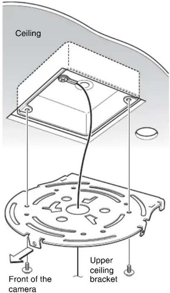
text_image
Ceiling Front of the camera Upper ceiling bracket3 Attach the lower ceiling bracket to the bottom of the camera using the supplied four screws ( M3 × 6).
Attach also the wire rope to the bottom of the camera using the supplied shoulder screw (⊕M4).
When attaching, align the screw holes on the bottom of the camera with those in the ceiling bracket, and set the triangular hole in the ceiling bracket at the front of the camera.

text_image
Wire rope Ceiling Shoulder screw ⊕M4 (supplied) ① ③ ② ④ ⊕M3×6 (supplied) Set the triangular hole at the front of the camera. Lower ceiling bracketTighten the screws a little bit at a time in the numbered order shown in the illustration. After all of the screws are temporarily tightened in the proper manner, securely tighten each one in turn.
Caution
To attach the ceiling bracket, use only the screws supplied with the camera. Using other screws may damage the camera.
4 Insert the raised protrusions on the lower ceiling bracket into the spaces provided in the upper ceiling bracket, and temporarily fix them by turning the camera with lower ceiling bracket clockwise.
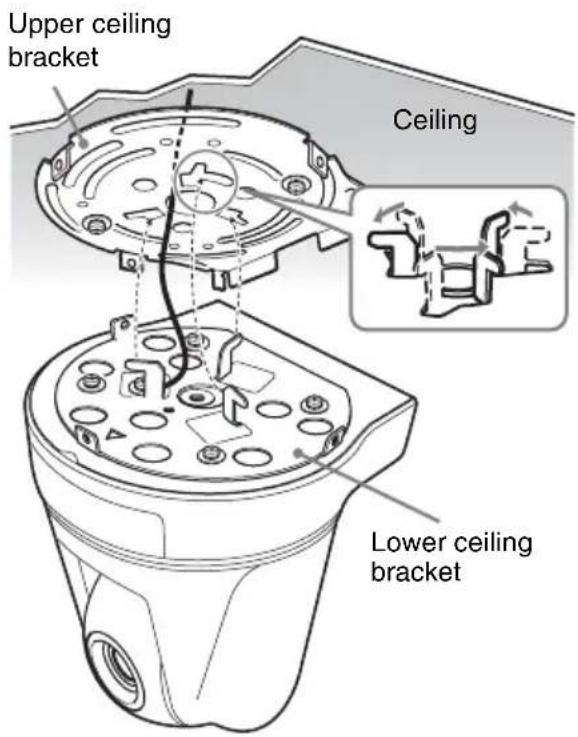
text_image
Upper ceiling bracket Ceiling Lower ceiling bracket5 Attach it using the supplied three screws (⊕M3 × 6), starting with the screw at position ①.

text_image
M3 × 6 (supplied) Ceiling ①6 Attach the mounting bracket cover around the ceiling bracket.
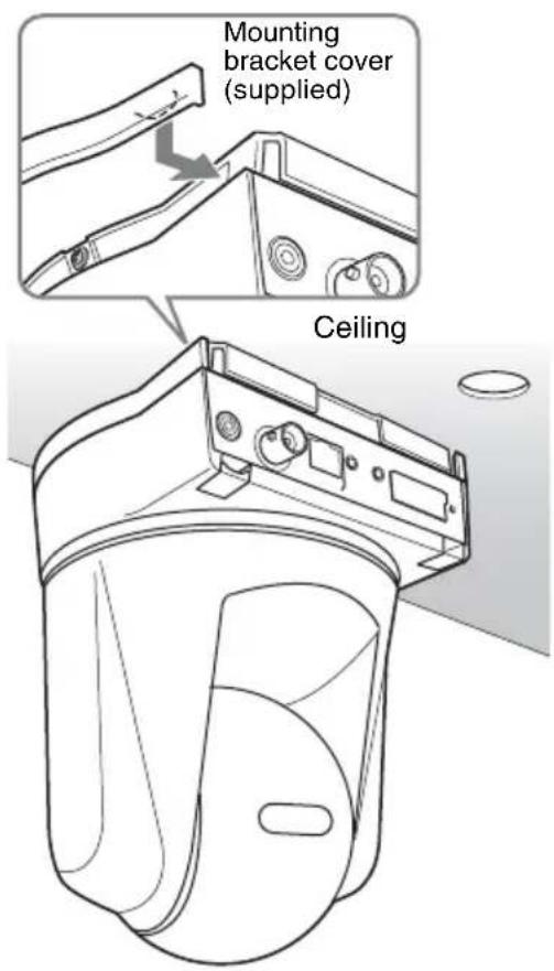
text_image
Mounting bracket cover (supplied) Ceiling7 Connect the cables to the connectors on the rear of the camera.
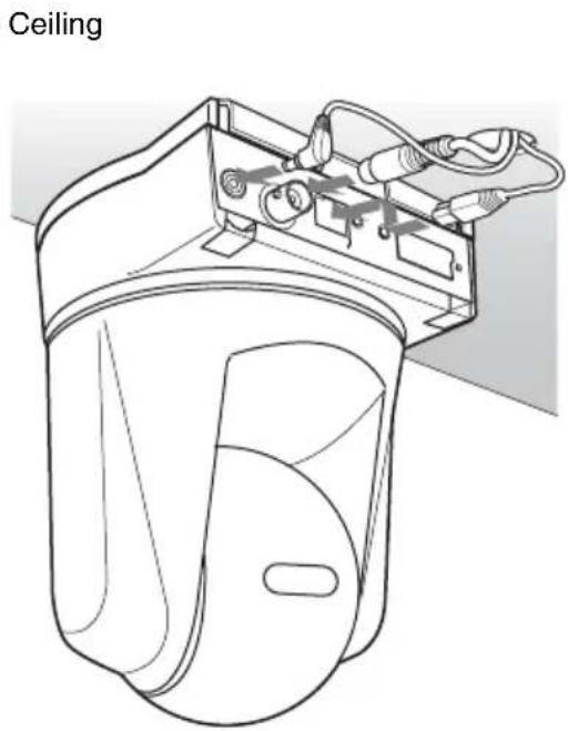
natural_image
Line drawing of a ceiling-mounted device with attached wiring and a door (no text or symbols)8 To extend the cables through the rear of the cable cover, cut out the thinner portion of the cover using a cutter knife.

natural_image
Pure 3D wireframe diagram of a mechanical part with no text, numbers, or symbols9 Temporarily attach the cable cover by inserting the raised protrusions on the cable cover into the gaps at the rear of the upper ceiling cover. Then fix the cable cover using the supplied two screws ( M3 ×6).

text_image
Ceiling ⊕M3 × 6 (supplied)Note
Take proper steps to ensure that the load of the connected cables does not cause problems.
Removing the camera
1 Remove two screws used to attach the cable cover in step 9 of "Installation" and remove the cable cover.
2 Disconnect the cables from the connectors at the rear of the camera.
3 Remove the mounting bracket cover that is attached in step 6 of "Installation". First take off the tab on the edge as in the illustration.
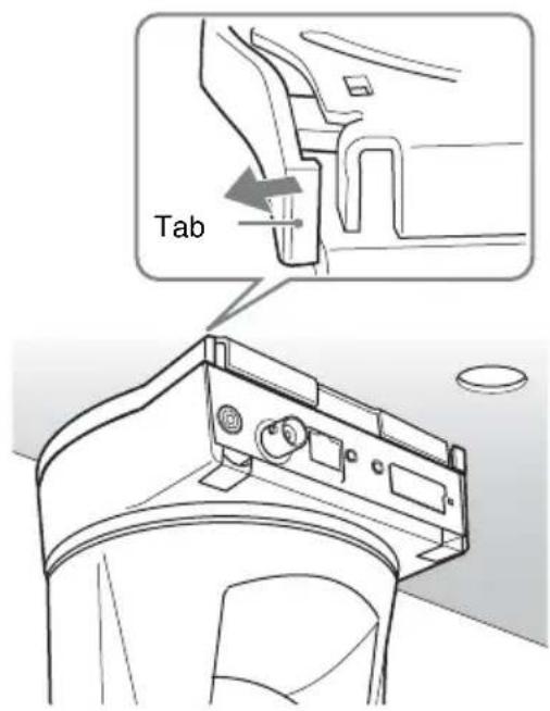
text_image
Tab4 Remove three screws used to attach the camera in step 5 of "Installation."
5 Pushing the entire camera up towards the ceiling, turn the camera counterclockwise as far as it goes, then pull it out.
Installing the Camera on the Desk Top
When you install the camera, always install it on a level surface. If you have to install it on a sloping or uneven surface, make sure that the place where you install it is within ±5 degrees of the horizontal in order to ensure the pan/tilt mechanism functions properly. In this case, be sure to take the fall-prevention measures.
1 Paste the supplied four rubber feet on the bottom of the camera.

natural_image
Technical line drawing of a mechanical component with mounting holes and internal features (no text or symbols)2 Turn the Sony badge on the front to fit top and bottom.
3 Connect the AC power adaptor and attach the plug retainer using the supplied screw ( M3 × 6) to prevent it coming out.
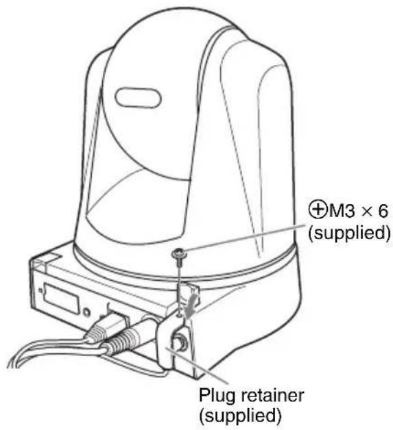
text_image
M3 × 6 (supplied) Plug retainer (supplied)4 Place the camera on the desktop.

natural_image
Line drawing of a mechanical component with concentric circular features (no text or symbols)Note
By default, the images from the camera are displayed normally when the camera is installed on the ceiling. To display the images from the camera in correct way when you place the camera on the desk top, use the E.flip function.
For the setting of the E.flip function, see the User's Guide stored in the supplied CD-ROM.
Connecting to a Computer or a Network
To connect to the computer, use a commercially available network cable (cross cable).
To connect to the network, use a commercially available network cable (straight cable).
System Requirements
These are the requirements for the computer that displays the image or controls the camera.
Processor
Intel Pentium 4, 1.5 GHz or higher (Pentium 4, 2.4 GHz or higher recommended)
RAM
256 MB or more
os
Microsoft Windows 2000, Windows XP
Web browser
Microsoft Internet Explorer Ver. 6.0 or later
Connecting the Camera to a Computer
Using a commercially available network cable (cross), connect the LAN port on the camera to the network connector of a computer.

text_image
SNC-RZ50N/RZ50P (rear) CLASS 2 WIRING SEE INSTRUCTION MANUAL LAN 10 5 6 7 8 9 4 3 3 1 LAN Network cable (cross, not supplied) Network connector ComputerConnecting the Camera to a Local Network
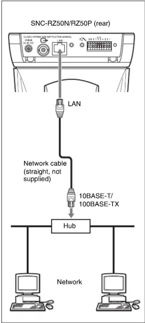
Using a commercially available network cable, connect the LAN port on the camera to a hub in the network.
flowchart
graph TD
    A["LAN"] -->|Network cable (straight, not supplied)| B["10BASE-T/100BASE-TX"]
    B --> C["Hub"]
    C --> D["Computer"]
    C --> E["Computer"]
    F["SNC-RZ50N/RZ50P (rear)"] --> G["Class 2 Wiring See Instruction Manual"]
    G --> H["LAN"]
    H --> I["108 8 7 3 5 4 3 2 1"]
Connecting Power
Connect the supplied power cord to the supplied AC power adaptor, then connect the DC IN 12V connector of the camera and an AC outlet.

text_image
CLASS 2 WIRING SEE INSTRUCTION MANUAL DC MIN LAN 10 3 6 7 6 5 4 3 2 1 AC power adaptor To an AC outletAssigning the IP Address to the Camera
To connect the camera to a network, you need to assign a new IP address to the camera.
Before assigning the IP address, connect the camera to a computer or a network.
For details, see “Connecting to a Computer or a Network” on page 20.
You can assign the IP address in two ways:
• Using the setup program stored in the supplied CD-ROM
For details on the operations, see "Assigning the IP Address Using the Setup Program" on page 23.
- Using the ARP (Address Resolution Protocol) commands
Open the command prompt on the computer and enter the specified ARP commands.
For details on the operations, see "Assigning the IP Address to the Camera Using ARP Commands" in the User's Guide stored in the supplied CD-ROM.
Note
For determining the IP address to be assigned to the camera, consult your system administrator.
Note for Windows XP Service Pack 2
- The Setup Program may not operate correctly if you use a personal firewall or antivirus software in your computer. In that case, disable the software or assign an IP address to the camera using another method. See the User's Guide stored in the supplied CD-ROM.
- If you use Windows XP Service Pack 2, disable the Windows Firewall function. Otherwise, the IP Setup Program will not operate correctly. To disable Windows Firewall, perform the following operation.
1 Open Windows Firewall from Control Panel.
On the category display, you can find Windows Firewall in Security Center.
2 Select Off, and click OK.
Assigning the IP Address Using the Setup Program
1 Insert the supplied CD-ROM disc into your CD-ROM drive.
A cover page appears automatically in your Web browser.
If it does not appear automatically in the Web browser, double-click on the index.htm file on the CD-ROM.
2 Click the Setup icon of IP Setup Program.
The File Download dialog opens.
3 Click Open.
Note
You cannot install the IP Setup Program properly if you click Save in the File Download dialog.
Delete the downloaded file, and click the Setup icon again.
4 Install the IP Setup Program to your computer following the wizard displayed.
If “Software License Agreement” is displayed, read it carefully and accept the agreement to continue the installation.
5 Start the IP Setup Program.
The program detects the network camera(s) connected on the local network and lists it (them) on the Network tab window.

text_image
IP Setup Program ver1.3.5 DataSet | Bandwidth control | Date time | IPPoE | MAC address IP address Model Serial No.Vanien No. 001014a-cd-77-t8 192.168.0.100 SNC-RZSON 001015 1.00 Obtain an P address automatically Use the following P address P address Subtermark Densit activity Obtain DNS server address automatically Use the following DNS server address Primary DNS server address Secondary DNS server address Third DNS server address Fourth DNS server address HTTP port No. 80 (1024 to 85535) Administrator name: Administrator password: Finish Cancel OK6 Click the camera to which you want to assign a new IP address in the list.
| MAC address | IP address | Model | Serial No. | Version No. |
| 08-01-4=cc677-b8 | 132.160.0.100 | ENCPC50N | 001015 | 1.00 |
The network settings for the selected camera are displayed.
7 Set the IP address.
To obtain the IP address automatically from a DHCP server:
Select Obtain an IP address automatically.
- Obtain an IP address automatically
C Use the following IP address
The IP address, Subnet mask and Default gateway are assigned automatically.
To specify the IP address manually:
Select Use the following IP address, and type the IP address, Subnet mask
and Default gateway in the relevant boxes.

text_image
Obtain on P address automatically Use the following P address IP address 192 188 0 100 Subnet mask 255 0 0 0 Default gateway . . .Note
When you select Obtain an IP address automatically, make sure that a DHCP server is operating on the network.
8 Set the DNS server address.
To obtain the DNS server addresses automatically:
Select Obtain DNS server address automatically.

text_image
Obtain DNS server address automatically Use the following DNS server addressTo specify the DNS server addresses manually:
Select Use the following DNS server address, and type the Primary DNS server address and Secondary DNS server address in the relevant boxes.

text_image
Use the following DNS server address Primary DNS server address 182 . 168 . 0 . 200 Secondary DNS server address 182 . 150 . 0 . 201 Third DNS server address Fourth DNS server addressNote
The Third DNS server address and Fourth DNS server address are invalid for this camera.
9 Set the HTTP port number.

Normally select 80 for the HTTP port No. To use another port number, select the text box and type a port number between 1024 and 65535.
10Type the Administrator name and Administrator password.

text_image
Administrator name: admin Administrator password: wwwThe default settings of both items are "admin."
Note
You cannot change the Administrator name and Administrator password in this step. To change these items, see “Setting the User – User Menu” of the User’s Guide stored in the supplied CD-ROM.
11 Confirm that all items are correctly set, then click OK.

If "Setting OK" is displayed, the IP address is correctly assigned.

text_image
Information Setting OK OK12To access the camera directly, double-click the camera name in the list.
| MAC address | IP address | Model | Serial No. | Version No. |
| 00:01-4:ccd-77-b8 | 192168.0.100 | SNC-P25CN | 601015 | 1.09 |
Tip
The factory setting of the camera network is as follows.
IP address: 192.168.0.100
Subnet mask: 255.0.0.0
Wireless LAN setting
Type: Adhoc
SSID: snc-rz50
Channel: 11 ch
WEP: nothing
IP address: 10.0.0.100
Subnet mask: 255.0.0.0
The welcome page of the network camera is displayed.

text_image
IPELA Network Camera SNC-RZ50N Enter M12034 ● Automatic home J560 ● Automatic home ● Remote digital home Setting Digital Connection SONY Copyright 2005 Scan Connection. All rights reserved.Note
If the IP address is not set correctly, the welcome page does not appear after step 12. In this case, try to set the IP address again.
Accessing the Camera Using the Web Browser
When the IP address has been assigned to the camera, check that you can actually access the camera using the Web browser installed in your computer.
This section explains how to access the camera using the Internet Explorer.
For details on the operations using the Web browser, see the User's Guide stored in the supplied CD-ROM.
1 Start the Web browser on the computer and type the IP address of this camera in the URL box.
Example:
Address
http://192.168.0.100
The Welcome page is displayed.

text_image
IPELA Network Camera SNC-RZ50N Enter MPB04 • AutomIC camera IPE07 • AutomIC camera • User up shot camera Setting English Version SONY Copyright ©2013/80/Chip purchase, all rights reserved.2 Click Enter.
The main viewer is displayed.
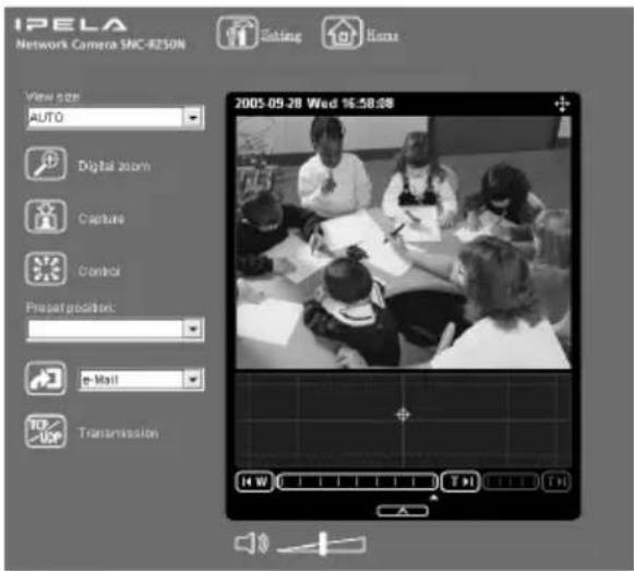
text_image
IPELA Network Camera SNC-8250N Editing Items View size AUTO Digital zoom Capture Control Preset position: e Mail Transmission 2003-05-20 Wed 16:58:08 H WWhen the main viewer is correctly displayed, accessing the camera is confirmed.
When the main viewer of the camera is displayed for the first time
When you click Enter, "Security Warning" is displayed.
When you click OK, the ActiveX control is installed and the main viewer is displayed.

text_image
Security Warning Do you want to install and run "Sony Nervox: Camera viewer" signed on 9/27/2005 7:28 PM and distributed by: Sony Corporation Publisher authenticity verified by VerSign Class 3 Code Signing 2004 CA Caution: Sony Corporation assets that this content is safe. You should only install/view this content if you trust Sony Corporation to make that assertion. □ Always trust content from Sony Corporation Yes No Move InfoNotes
- If Automatic configuration is enabled in the Local Area Network (LAN) Settings on Internet Explorer, the image may not be displayed. In this case, disable Automatic configuration and set the Proxy server manually. For setting the Proxy server, consult your network administrator.
- When you install ActiveX viewer on Windows 2000 or Windows XP, you should have logged in the computer as the Administrator.
Tip
Every page of this software is optimized as display character size Medium for Internet Explorer.
To display the Welcome page correctly
To operate the welcome page correctly, set the security level of the Internet Explorer to Medium or lower, as follows:
1 Select Tool from the menu bar for Internet Explorer, then select Internet Options and Security tab in sequence.
2 Click the Internet icon (when using the camera via the Internet) or Local intranet icon (when using the camera via a local network).
3 Set the slider to Medium or lower. (If the slider is not displayed, click Default Level.)
When using antivirus software, etc. in the computer
- When you use antivirus software, security software, personal firewall or pop-up blocker in your computer, the camera performance may be reduced, for example, the frame rate for displaying the image may be lower.
- The Web page displayed when you log in the camera uses Java Script. The display of the Web page may be affected if you use antivirus software or other software described above in your computer.
Specifications
Network
Protocol TCP/IP, ARP, ICMP, HTTP, FTP (server/client), SMTP (client), DHCP (client), DNS (client), NTP (client), SNMP (MIB-2), RTP/RTCP
Compression
Video compression format
JPEG/MPEG4/H.264
Audio compression format
G.711/G.726 (40,32,24,16 kbps)
Image size 640 × 480 (VGA), 320 × 240
(QVGA), 160 × 120 (QQVGA)
Maximum frame rate
SNC-RZ50N: 30 fps
SNC-RZ50P: 25 fps
Web browser Internet Explorer Ver. 6.0 or later
(Available OS: Microsoft
Windows 2000, Windows XP)
Computer environments
CPU: Pentium 4, 1.5 GHz or
higher (Pentium 4, 2.4 GHz or higher recommended)
RAM: 256 MB or more
Display size: 1024 × 768
Maximum user access
20 users
Network security
Password (basic authentication), IP filtering
Homepage customization
Starting from a homepage in the built-in flash memory, a ATA memory card or an CF memory card possible
Other functions
Detection, image trimming, built-in clock, etc.
Camera
Signal system SNC-RZ50N: NTSC color system
SNC-RZ50P: PAL color system
Image device 1/4 type color CCD
Total picture elements:
SNC-RZ50N: Approx. 630,000
SNC-RZ50P: Approx.740,000
Effective picture elements:
SNC-RZ50N: Approx. 340,000
SNC-RZ50P: Approx. 400,000
Lens 26× (Optical), 12× (Digital)
f=3.5 to 91 mm, F1.6 to F3.8
Horizontal angle: 1.7° to 42.0°
Minimum object distance
TELE end: 1,500 mm (59 ^1/8 inches)
WIDE end: 320 mm (12 ^5 /8 inches)
Minimum illumination
2.2 lx (F1.6/50 IRE)
Shutter speed
1 to 1/10,000 s
Horizontal resolution
SNC-RZ50N : 450 TV (WIDE end)
SNC-RZ50P : 450 TV (WIDE end)
Video S/N 50 dB or more
Mechanism
Pan -170^ to +170^
Maximum speed: 300^/s
Tilt -90^ to +25^
Maximum speed: 300^/s
Interface
Network port 10BASE-T/100BASE-TX (RJ-45)
I/O port Sensor input : × 2, make contact
Alarm output : × 2, 24 V AC/DC, 1 A
(mechanical relay outputs
electrically isolated from the camera)
Serial interface RS-232C: ×1
Video output VIDEO OUT: BNC, 1.0 Vp-p,
75 ohms, unbalanced, sync negative
PC card slot PCMCIA Type II
CF card slot CF Type I/II
Microphone input
Minijack (monaural)
Plug-in-power supported (rated voltage: 2.5 V DC)
Recommended load impedance 2.2 khoms
Line output Minijack (monaural), Maximum
output level: 1 Vrms
Others
Power supply 12 V DC ± 10%
Power consumption
20 W max.
Operating temperature
0^ to +40^ (32°F to 104°F)
Storage temperature
-20^ to +60^ ( -4^ to +140^ )
Operating humidity
20 to 80 %
Storage humidity
20 to 95 %
Dimensions 166 × 140 × 142 mm (6 ^5 /8 × 5 ^5 /8
not including the projecting parts
Mass Approx. 1.2 kg (2 lb 10 oz)
Supplied accessories
CD-ROM (User's Guide and supplied programs) (1)
AC power adaptor (1)
AC power cord (1)
Upper ceiling bracket (1)
Lower ceiling bracket (1)
Cable cover (1)
Mounting bracket cover (1)
Screws ⊕M3 × 6 (9)
Shoulder screw ⊕M4 (1)
Plug retainer (1)
Rubber foot (4)
Fall-prevention wire rope (1)
Installation Manual (this document) (1)
B&P Warranty Booklet (1) (SNC-RZ50N only)
Optional accessories
In-ceiling bracket
YT-ICB550 (clear type/tinted type)
Mounting adaptor
YT-MA550
Wireless card SNCA-CFW1
Wireless LAN antenna
SNCA-AN1
Design and specifications are subject to change without notice.
Regular parts replacement
Some of the parts that make up this product (electrolytic condenser, for example) need replacing regularly depending on their life expectancies.
The lives of parts differ according to the environment or condition in which this product is used and the length of time it is used, so we recommend regular checks.
Consult the dealer from whom you bought it for details.
Front

text_image
140 (5 5/8) 166 (6 5/8)Front (with ceiling brackets)

text_image
140 (5 5/8) 178 (7 1/8)Side
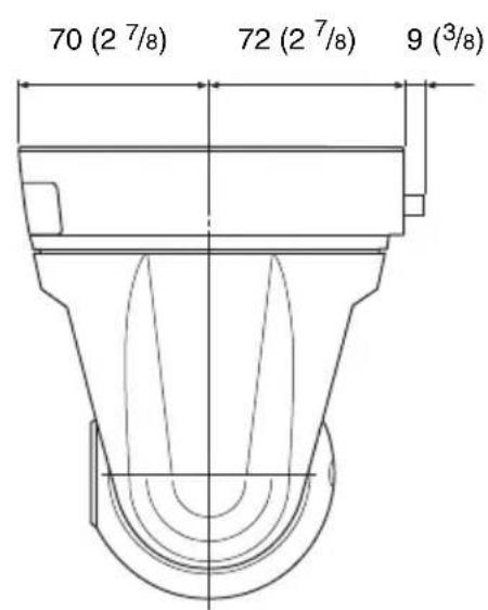
text_image
70 (2 7/8) 72 (2 7/8) 9 (3/8)Side (with cable cover)
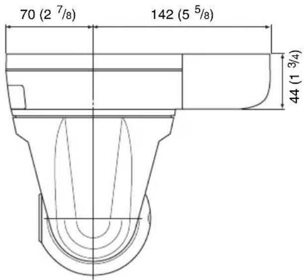
text_image
70 (2 7/8) 142 (5 5/8) 44 (1 3/4)Unit: mm (inches)
Bottom

text_image
70 (2 7/8) 60 (2 3/8) Hole 4 - M3 (× 4) Screw hole for wire ropeUpper ceiling bracket

text_image
83.5 (3 3/8) ø 96 40° Hole 4 - ø 4.4 (3/16) 40° 46 (1 15/16) 40° 30° 30° Unit: mm (inches) Ø 88.9 (3 1/2) Hole width 4.4 (3/16) (× 4) Ø 107.3 (4 1/4) Hole width 4.4 (3/16) (× 4) Ø 121.2 (4 7/8) Hole width 4.4 (3/16) (× 4) Ø 83.5 (3 3/8) Hole width 4.4 (3/16)(× 2) (Adjustable range: ±20°)Pin Assignment and Use of I/O Port
Pin assignment of I/O port

| Pin No. | Pin name |
| 1 Sensor In 1 + | |
| 2 Sensor In 1 – (GND) | |
| 3 Sensor In 2 + | |
| 4 Sensor In 2 – (GND) | |
| 5 Alarm Out 1 + | |
| 6 Alarm Out 1 – | |
| 7 Alarm Out 2 + | |
| 8 Alarm Out 2 – | |
| 9 RS232C · RX | |
| 10 RS232C · TX | |
Using the I/O receptacle
While holding down the button under the slot to which you want to connect the wire (AWG No. 28 to 22) with a small slotted screwdriver, insert the wire into the slot. Then release the screwdriver from the button.
1

text_image
10 9 8 7 6 5 4 3 2 1 I/O Slotted screwdriver Wire2
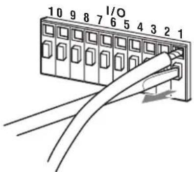
text_image
10 9 8 7 6 5 4 3 2 1 I/ORepeat this procedure to connect all required wires.
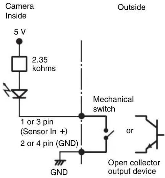
Wiring diagram for sensor input
Mechanical switch/open collector output device
text_image
Camera Inside 5 V 2.35 kohms 1 or 3 pin (Sensor In +) 2 or 4 pin (GND) GND Outside Mechanical switch or Open collector output deviceWiring diagram for alarm output

text_image
Camera Inside 5 or 7 pin (Alarm output +) Magnet relay 24 V AC/24 V DC, 1 A or less 6 or 8 pin (Alarm output -) Outside 5 V Circuit example R GNDWhen You Discard the Camera
For environmental reasons, take out the lithium battery from the camera and discard it appropriately.
1 Remove the four screws illustrated below and detach the bottom panel.

natural_image
Technical line drawing of a vehicle dashboard with control panel and rear vent (no text or symbols)2 Hold the board on which the lithium battery is attached using long-nose pliers. Then, bend it in the direction of the arrow illustrated below to detach the battery.

text_image
Lithium batteryWARNING (for service personnel only)
There is danger of explosion if batteries are mishandled.
Dispose of batteries properly in accordance with the manufacturer's instructions and all applicable local regulations.
AVERTISSEMENT
natural_image
Technical line drawing of a mechanical component with no visible text or symbolsnatural_image
Line drawing of a rectangular electronic device with a coiled cable and connector (no text or symbols)natural_image
Line drawing of a cord with two connected power plugs (no text or symbols)natural_image
Line drawing of a cable with a plug and connector (no text or symbols)natural_image
Technical line drawing of a mechanical component with holes and mounting brackets (no text or symbols)natural_image
Technical line drawing of a mechanical component with symmetrical slots and central hole (no text or symbols)natural_image
Simple line drawing of a coiled cable with two connectors (no text or symbols)natural_image
Line drawing of a rectangular container or housing with a small protrusion on the side (no text or symbols)natural_image
Line drawing of a curved metal bracket or clamp (no text or symbols)Vis ⊕M3 × 6 (9)
Vis épaulée ⊕M4 (1)

natural_image
Simple line drawing of a bent metal bracket with a circular hole (no text or symbols)natural_image
Simple line drawing of four circles arranged in a 2x2 grid within a parallelogram (no text or symbols)text_image
Diagram of a car air conditioner unit with numbered parts and a close-up inset showing the internal structure.①Fente carte CF
text_image
Technical diagram of a device rear panel with numbered component labelsnatural_image
Line drawing of a hand holding a small object with a cross mark above, no text or symbols present
natural_image
Illustration of a hand holding a device with directional arrows indicating rotation or movement (no text or symbols)text_image
⊕M3 × 6 (fournies) Plafond ①natural_image
Line drawing of a washing machine with attached wiring and control panel (no text or symbols)natural_image
Pure technical line drawing of a 3D mechanical part with no text, numbers, or symbolstext_image
Plafond ⊕M3 × 6 (fournies)Remarque
natural_image
Technical line drawing of a mechanical component with mounting holes and internal features (no text or symbols)natural_image
Line drawing of a mechanical component with concentric circular features (no text or symbols)Remarque
text_image
IP Setup Program ver1.3.5 DataSet | Bandwidth control | Date time | IPPoE | MAC address P address Model Serial No.Version No. 001014a-cd-77-t8 192.168.0.100 SNC-RZSON 001015 1.00 Obtain an P address automatically Use the following P address P address Send records Dens A capacity Obtain DNS server address automatically Use the following DNS server address Primary DNS server address Secondary DNS server address Using DNS server address Form DNS server address HTTP port No. 80 (1024 to 85535) Administrator name: Administrator password: Finish Cancel OK| MAC address | IP address | Model | Serial No. | Version No. |
| 00-01-4a-cd-77-b8 | 132.168.0.100 | SNC-PSSON | 001015 | 1.00 |
- Obtain an IP address automatically
C Use the following IP address
text_image
Obtain on IP address automatically Use the following IP address IP address 192 . 168 . 0 . 100 Subnet mask 255 . 0 . 0 . 0 Default gatewayRemarque
Obtain DNS server address automatically
Use the following DNS server address
text_image
Use the following DNS server address Primary DNS server address 192 . 168 . 0 . 200 Secondary DNS server address 192 . 159 . 0 . 201 Third DNS server address . Fourth DNS server addressRemarque
text_image
Administrator name admin Administrator password newtext_image
Information Setting OK OK| MAC address | IP address | Model | Serial No. | Version No. |
| 00-01-4a-cd-77-68 | 192188.0.100 | SNC-R250N | 001015 | 1.00 |
Conseil
text_image
IPELA Network Camera SNC-RZ50N Enter METAL • Anti-CC name JETY • Anti-CC name • Semi-ppolar name Setting English: Sony.com SONY Copyright © 2007 Sony Corporation. All rights reserved.Remarque
text_image
IPELA Network Camera SNC-RZ50N Enter NETB34 • Automatic camera JF507 • Automatic camera • Mini pixel camera Setting Be glad: Automatic SONY Copyright 800 Group Cup version, All rights reserved.text_image
IPELA Network Camera SNC-R250N Rating Home View Size AUTO Digital zoom Capture Control Preset position: 8 Mail Transmission 2005.09.28 Wed 16:58:08 + - 4 W T D T Htext_image
Security Warning Do you want to install and run "Sony Network Camera viewer" signed on 9/27/2005 7:28 PM and distributed by: Sony Corporation Publisher authenticity verified by VerSign Class 3 Code Signing 2004 CA Caution: Sony Corporation assets that this content is safe. You should only install/view this content if you trust Sony Corporation to make that assertion. □ Always trust content from Sony Corporation Yes No Move InfoRemarques
Protocole TCP/IP, ARP, ICMP, HTTP, FTP (serveur/client), SMTP (client), DHCP (client), DNS (client), NTP (client), SNMP (MIB-2), RTP/RTCP
Compression
G.711/G.726 (40, 32, 24, 16 kbps)
(QVGA), 160 × 120 (QQVGA)
Taux de trame maximum
SNC-RZ50N : 30 trames/seconde
SNC-RZ50P : 25 trames/seconde
Navigateur Internet
natural_image
Technical line drawing of a device rear panel with ports and control panels (no text or symbols)natural_image
Technical line drawing of a mechanical component with no visible text or symbolsnatural_image
Line drawing of a rectangular electronic device with a coiled cable and two ports, no text or symbols present.natural_image
Line drawing of a pair of electrical plugs tied together (no text or symbols)Modelo para Europa

natural_image
Line drawing of a cable with a plug and terminal outlet (no text or symbols)natural_image
Technical line drawing of a mechanical component with holes and mounting holes (no text or symbols)natural_image
Technical line drawing of a mechanical component with symmetrical slots and central hole (no text or symbols)natural_image
Simple line drawing of a coiled cable or wire with two connectors (no text or symbols)natural_image
Line drawing of a rectangular container or housing with a curved top and side connectors (no text or symbols)natural_image
Line drawing of a curved metal bracket or clamp (no text or symbols)Tornillos ⊕M3 × 6 (9)

Tornillo con pivote ⊕M4 (1)

Soporte de enchufe (1)
natural_image
Simple line drawing of a bent metal bracket with a circular hole (no text or symbols)Base de goma (4)

natural_image
Simple geometric diagram of four circles arranged in a 2x2 grid within a parallelogram (no text or symbols)text_image
Diagram of a car air conditioner unit with numbered parts and an inset showing airflow direction①Ranura de la tarjeta CF
⑩Puerto LAN (red) (RJ45)
text_image
Diagram illustrating hand press application on a device, showing two states of cancellation with X marks and directional arrows.natural_image
Technical line drawing of a mechanical component with mounting holes and internal features (no text or symbols)natural_image
Line drawing of a mechanical component with concentric circular features (no text or symbols)Nota
text_image
IP Setup Program ver1.3.5 DataSet | Bandwidth control | Date time | IPPoE | MAC address P address Model Serial No.Version No. 001014a-cd-77-t8 192.168.0.100 SNC-RZSON 001015 1.00 Obtain an P address automatically Use the following P address P address Send records Dens A capacity Obtain DNS server address automatically Use the following DNS server address Primary DNS server address Secondary DNS server address Using DNS server address Form DNS server address HTTP port No. 80 (1024 to 85535) Administrator name: Administrator password: Finish Cancel OK| MAC address | IP address | Model | Serial No. | Version No. |
| 00-01-4-cd77-b8 | 132.168.0.100 | SNCPSON | 001015 | 1.09 |
Seleccione Obtain an IP address automatically.
- Obtain an IP address automatically
C Use the following IP address
Se asignará automáticamente IP address, Subnet mask y Default gateway.
text_image
Obtain an IP address automatically Use the following IP address IP address 192 168 0 100 Subnet mask 255 0 0 0 Default gateway . . .Nota
- Obtain DNS server address automatically - Use the following DNS server address
text_image
Use the following DNS server address Primary DNS server address 192 168 0 200 Secondary DNS server address 192 168 0 201 Third DNS server address Fourth DNS server addressNota
Third DNS server address y Fourth DNS server address no son válidos para esta cámara.
text_image
Information Setting OK OKIP address: 192.168.0.100
Subnet mask: 255.0.0.0
IP address: 10.0.0.100
Subnet mask: 255.0.0.0
text_image
IPELA Network Camera SNC-RZ50N Enter M2B334 • Automatic camera J8503 • Automatic camera • Jams upgraded video Setting In glass 12mmeter SONY Copyright © IBM Group Corp. status: Air glasses reserved.2 Haga clic en Enter.
text_image
Security Warning Do you want to install and run "Sony Newveer Camera Viewer" signed on 9/27/2005 7:29 PM and distributed by: Sony Corporation Publisher authenticity verified by VerSign Class 3 Code Signing 2004 CA Caution Sony Corporation asserts that this content is safe. You should only install/view this content if you trust Sony Corporation to make that assertion. □ Always trust content from Sony Corporation Yes No Move InfoNotas
G.711/G.726 (40, 32, 24, 16 kbps)
Tamaño de imagen
640× 480 (VGA), 320× 240
(QVGA), 160 × 120 (QQVGA)