RP0900K - Router MAKITA - Free user manual and instructions
Find the device manual for free RP0900K MAKITA in PDF.

| Brand | Makita |
| Model | RP0900K |
| Product Type | Router |
| Collet Capacity | 6 mm, 8 mm, 1/4", 3/8" |
| Plunge Capacity | 0 – 35 mm |
| No Load Speed | 27 000 rpm |
| Overall Height | 217 mm |
| Net Weight | 2.7 kg |
| Double Insulation | Yes (class II) |
| Main Uses | Trimming, profiling of wood, plastic and similar materials |
| Power Supply | Single phase mains, voltage as per rating plate |
| Depth Adjustment | Stop rod and stop block with 3 hex bolts |
| Straight Guide | Included for straight cuts |
| Template Guide | Accessory for template work |
| Dust Extraction Adapter | Accessory for dust extraction |
| Sound Pressure Level | 92 dB(A) |
| Sound Power Level | 100 dB(A) |
| Vibration Emission (groove cutting) | 4.3 m/s² |
| Maintenance | Cleaning without aggressive solvents; maintenance by authorized service center |
| Optional Accessories | Bits, guides, adapters, etc. |
Frequently Asked Questions - RP0900K MAKITA
User questions about RP0900K MAKITA
0 question about this device. Answer the ones you know or ask your own.
Ask a new question about this device
Download the instructions for your Router in PDF format for free! Find your manual RP0900K - MAKITA and take your electronic device back in hand. On this page are published all the documents necessary for the use of your device. RP0900K by MAKITA.
USER MANUAL RP0900K MAKITA
GB Router Instruction manual
natural_image
Technical line drawing of a Makital electric drill press with visible components and mounting base (no text or symbols)009743


1 009744 2 009745
natural_image
Technical line drawing of a car seatbelt assembly (no text or symbols)3 009746 4 009747
natural_image
Mechanical assembly diagram showing hands operating a motor with rotating components (no text or labels)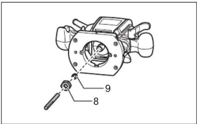
5 009748 6 216001
7 001984 8 001985
natural_image
Line drawing of hands operating a mechanical device on a workbench (no text or symbols)9 009749 10 009750
natural_image
Line drawing of hands operating a mechanical device with coiled tubing (no text or symbols)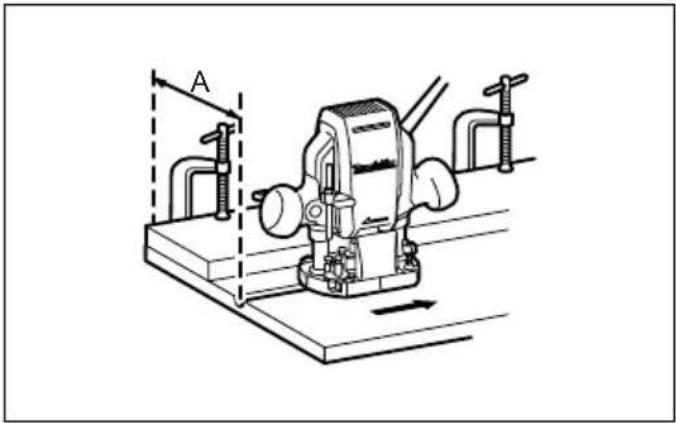
natural_image
Technical line drawing of a mechanical device with clamps and a base, no visible text or symbols11 009751 12 009752
natural_image
Line drawing of hands operating a mechanical device with coiled tubing (no text or symbols)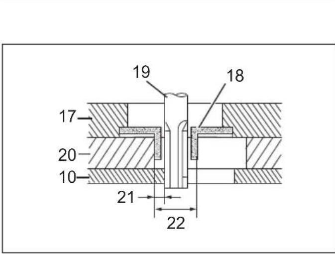
13 009753 14 003695
15 009754-1 16 009754-2
natural_image
Line drawing of a vacuum cleaner connected to a cylindrical device with hoses (no text or symbols)17 009755 18 005116
19 005117 20 005118
21 005120 22 005121
23 005125 24 005126
25 005129 26 005130
27 005131 28 005132

29 005133 30 005134
31 005135
ENGLISH (Original instructions)
Explanation of general view
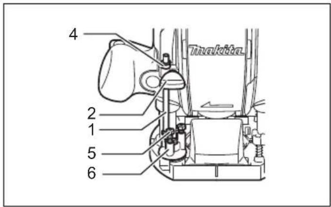
| 1. Stopper pole | 10. Workpiece | 19. Bit |
| 2. Screw | 11. Bit revolving direction | 20. Templet |
| 3. Lock lever | 12. View from the top of the tool | 21. Distance (X) |
| 4. Depth pointer | 13. Feed direction | 22. Outside diameter of the templet guide |
| 5. Adjusting hex bolt | 14. Straight guide | |
| 6. Stopper block | 15. Guide bar | 23. Dust nozzle |
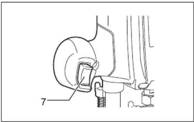
| 7. Switch trigger | 16. Clamp screw | 24. Thumb screw |
| 8. Collet nut | 17. Base | |
| 9. Collet cone | 18. Templet guide |
SPECIFICATIONS
| Model RP0900 | |
| Collet chuck capacity 6mm, 1/4", 8 mm and/or 3/8" | |
| Plunge capacity 0 - 35 mm | |
| No load speed (min ^-1 ) 27,000 | |
| Overall height 217 mm | |
| Net weight 2.7 kg | |
| Safety class | ☐/II |
- Due to our continuing program of research and development, the specifications herein are subject to change without notice.
- Specifications may differ from country to country.
• Weight according to EPTA-Procedure 01/2014
Intended use
ENE010-1
The tool is intended for flush trimming and profiling of wood, plastic and similar materials.
Power supply
ENF002-2
The tool should be connected only to a power supply of the same voltage as indicated on the nameplate, and can only be operated on single-phase AC supply. They are double-insulated and can, therefore, also be used from sockets without earth wire.
General power tool safety warnings
GEA010-2

WARNING: Read all safety warnings, instructions, strations and specifications provided with this power tool. Failure to follow all instructions listed below may result in electric shock, fire and/or serious injury.
Save all warnings and instructions for future reference.
The term “power tool” in the warnings refers to your mains-operated (corded) power tool or battery-operated (cordless) power tool.
ROUTER SAFETY WARNINGS
GEB018-5
- Hold the power tool by insulated gripping surfaces only, because the cutter may contact its own cord. Cutting a "live" wire may make exposed metal parts of
the power tool "live" and could give the operator an electric shock.
- Use clamps or another practical way to secure and support the workpiece to a stable platform. Holding the work by your hand or against the body leaves it unstable and may lead to loss of control.
- The cutter bit shank must match the designed collet chuck.
- Only use a bit that is rated at least equal to the maximum speed marked on the tool.
- Wear hearing protection during extended period of operation.
- Handle the router bits very carefully.
- Check the router bit carefully for cracks or damage before operation. Replace cracked or damaged bit immediately.
- Avoid cutting nails. Inspect for and remove all nails from the workpiece before operation.
- Hold the tool firmly with both hands.
- Keep hands away from rotating parts.
- Make sure the router bit is not contacting the workpiece before the switch is turned on.
- Before using the tool on an actual workpiece, let it run for a while. Watch for vibration or wobbling that could indicate improperly installed bit.
- Be careful of the router bit rotating direction and the feed direction.
- Do not leave the tool running. Operate the tool only when hand-held.
-
Always switch off and wait for the router bit to come to a complete stop before removing the tool from workpiece.
-
Do not touch the router bit immediately after operation; it may be extremely hot and could burn your skin.
- Do not smear the tool base carelessly with thinner, gasoline, oil or the like. They may cause cracks in the tool base.
- Some material contains chemicals which may be toxic. Take caution to prevent dust inhalation and skin contact. Follow material supplier safety data.
- Always use the correct dust mask/respirator for the material and application you are working with.
SAVE THESE INSTRUCTIONS.
WARNING:
DO NOT let comfort or familiarity with product (gained from repeated use) replace strict adherence to safety rules for the subject product. MISUSE or failure to follow the safety rules stated in this instruction manual may cause serious personal injury.
FUNCTIONAL DESCRIPTION
CAUTION:
- Always be sure that the tool is switched off and unplugged before adjusting or checking function on the tool.
Adjusting the depth of cut (Fig. 1)
Place the tool on a flat surface. Loosen the screw securing the stopper pole.
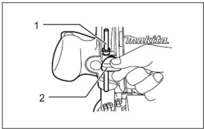
Loosen the lock lever and lower the tool body until the bit just touches the flat surface. Tighten the lock lever to lock the tool body. (Fig. 2)
Next, lower the stopper pole until it makes contact with the adjusting hex bolt. Align the depth pointer with the "0" graduation.
Raise the stopper pole until the desired depth of cut is obtained. The depth of cut is indicated on the scale (1 mm per graduation) by the depth pointer. Then tighten the screw to secure the stopper pole.
Now, your predetermined depth of cut can be obtained by loosening the lock lever and then lowering the tool body until the stopper pole makes contact with the adjusting hex bolt. (Fig. 3)
CAUTION:
- Since excessive cutting may cause overload of the motor or difficulty in controlling the tool, the depth of cut should not be more than 15mm at a pass when cutting grooves with an 8mm diameter bit.
- When cutting grooves with a 20 mm diameter bit, the depth of cut should not be more than 5 mm at a pass. When you wish to cut grooves more than 15 mm deep with an 8 mm diameter bit or more than 5 mm deep with a 20 mm diameter bit, make several passes with progressively deeper bit settings.
Stopper block (Fig. 3)
The stopper block has three adjusting hex bolts which raise or lower 0.8 mm per turn. You can easily obtain three different depths of cut using these adjusting hex bolts without readjusting the stopper pole.
Adjust the lowest hex bolt to obtain the deepest depth of cut, following the method of "Adjusting depth of cut".
Adjust the two remaining hex bolts to obtain shallower depths of cut. The differences in height of these hex bolts are equal to the differences in depths of cut.
To adjust the hex bolts, turn the hex bolts. The stopper block is also convenient for making three passes with progressively deeper bit settings when cutting deep grooves.
CAUTION:
When using a bit having total length of 60 mm or more, or edge length of 35 mm or more, the depth of cut cannot be adjusted as previously mentioned. To adjust, proceed as follows:
Loosen the lock lever and carefully adjust bit protrusion below the tool base to the desired depth of cut by moving the tool body up or down. Then retighten the lock lever to lock the tool body at that depth of cut. Keep the tool body locked at this position during use. Since the bit always protrudes from the tool base, be careful when handling the tool.
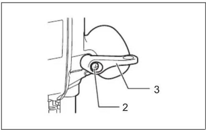
Adjusting the lock lever (Fig. 2)
The locked position of the lock lever is adjustable. To adjust it, remove the screw securing the lock lever. The lock lever will come off. Set the lock lever at the desired angle. After adjustment, tighten the lock lever clockwise.
Switch action (Fig. 4)
CAUTION:
- Before plugging in the tool, always check to see that the switch trigger actuates properly and returns to the "OFF" position when released.
To start the tool, simply pull the switch trigger. Release the switch trigger to stop.
ASSEMBLY
CAUTION:
• Always be sure that the tool is switched off and unplugged before carrying out any work on the tool.
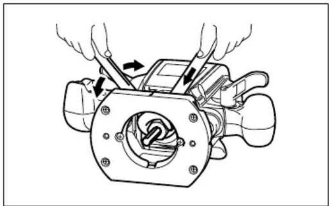
Installing or removing the bit (Fig. 5)
CAUTION:
- Install the bit securely. Always use only the wrenches provided with the tool. A loose or overtightened bit can be dangerous.
- Do not tighten the collet nut without inserting a bit. It can lead to breakage of the collet cone.
Insert the bit all the way into the collet cone and tighten the collet nut securely with the two wrenches.
Use the correct size collet cone for the bit which you intend to use.
To remove the bit, follow the installation procedure in reverse.
Changing the collet cone (Fig. 6)
CAUTION:
- Use the correct size collet cone for the bit that you are going to use.
- Do not tighten the collet nut without installing a bit, or the collet cone may break.
To change the collet cone, loosen the collet nut and remove. Replace the installed collet cone with desired collet cone. Reinstall collet nut.
OPERATION
Set the tool base on the workpiece to be cut without the bit making any contact. Then turn the tool on and wait until the bit attains full speed. Lower the tool body and move the tool forward over the workpiece surface, keeping the tool base flush and advancing smoothly until the cutting is complete.
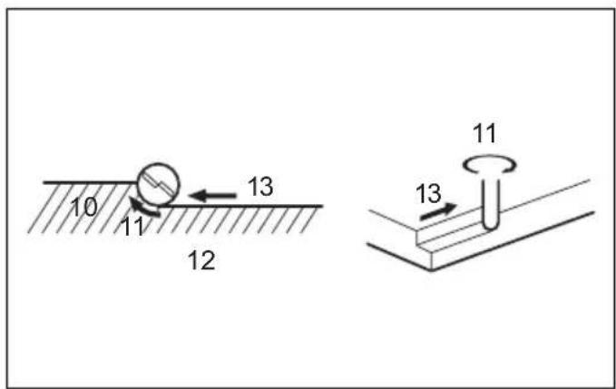
When doing edge cutting, the workpiece surface should be on the left side of the bit in the feed direction. (Fig. 7)
NOTE:
- Moving the tool forward too fast may cause a poor quality of cut, or damage to the bit or motor.
Moving the tool forward too slowly may burn and mar the cut. The proper feed rate will depend on the bit size, the kind of workpiece and depth of cut.
Before beginning the cut on the actual workpiece, it is advisable to make a sample cut on a piece of scrap lumber. This will show exactly how the cut will look as well as enable you to check dimensions. - When using the straight guide, be sure to install it on the right side in the feed direction. This will help to keep it flush with the side of the workpiece. (Fig. 8)
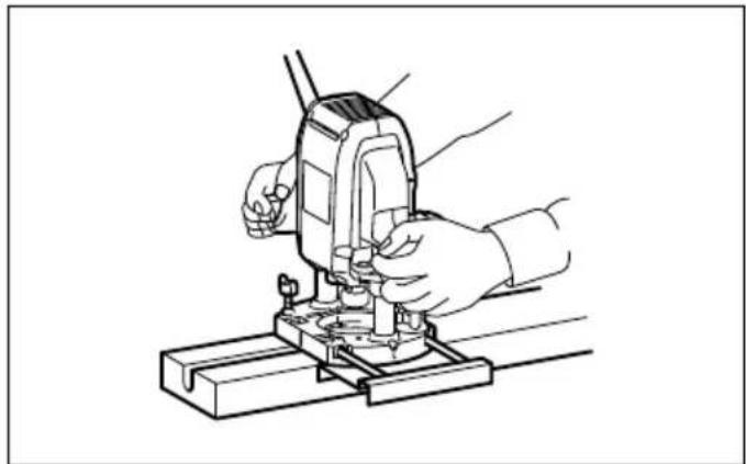
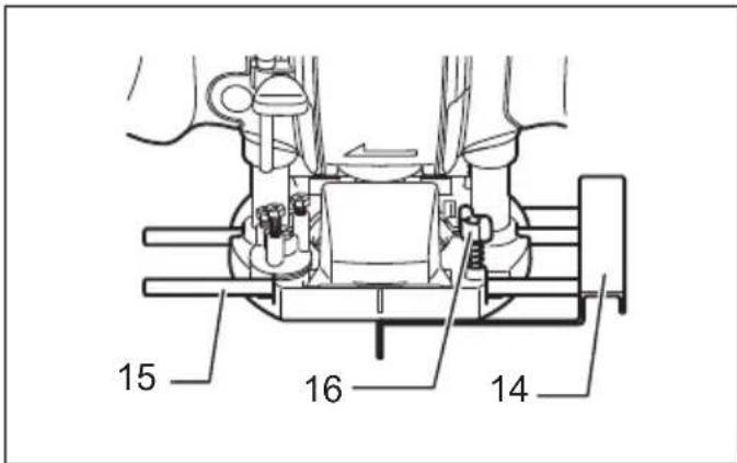
Straight guide (Fig. 9)
The straight guide is effectively used for straight cuts when chamfering or grooving.
To install the straight guide, insert the guide bars into the holes in the tool base. Adjust the distance between the bit and the straight guide. At the desired distance, tighten the wing bolts to secure the straight guide in place. (Fig. 10) When cutting, move the tool with the straight guide flush with the side of the workpiece.
If the distance (A) between the side of the workpiece and the cutting position is too wide for the straight guide, or if the side of the workpiece is not straight, the straight guide cannot be used. In this case, firmly clamp a straight board to the workpiece and use it as a guide against the router base. Feed the tool in the direction of the arrow. (Fig. 11)
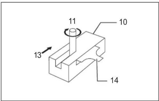
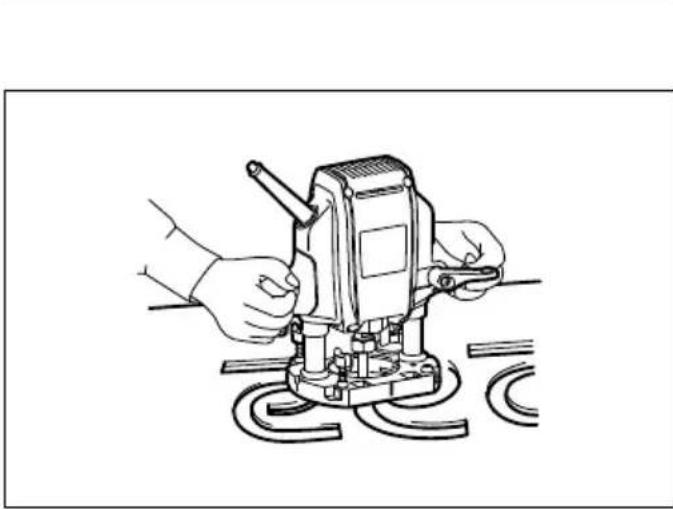
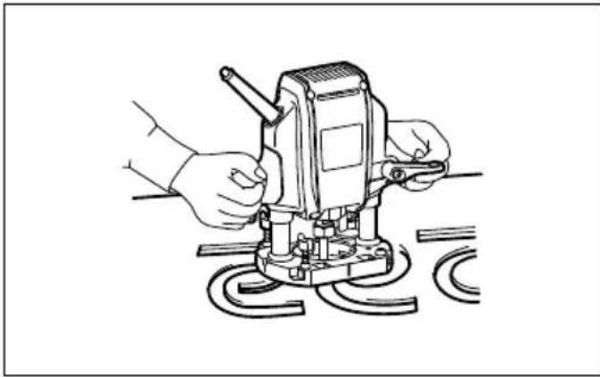
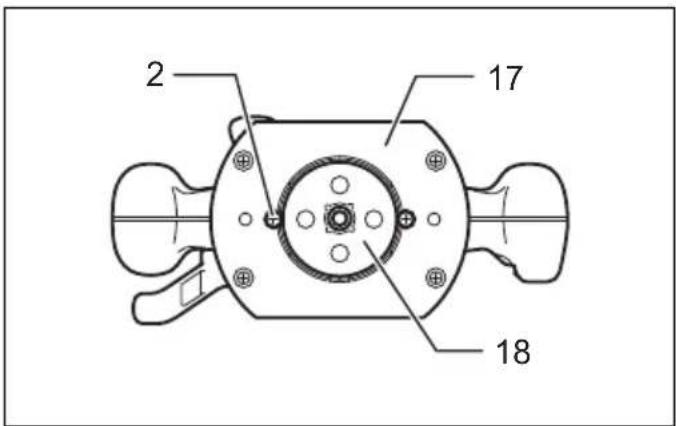
Templet guide (Accessory) (Fig. 12)
The templet guide provides a sleeve through which the bit passes, allowing use of the tool with templet patterns.
To install the templet guide, loosen the screws on the tool base, insert the templet guide and then tighten the screws. (Fig. 13)
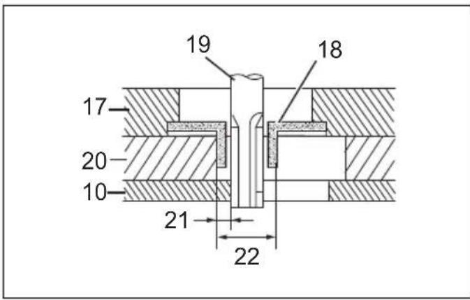
Secure the templet to the workpiece. Place the tool on the templet and move the tool with the templet guide sliding along the side of the templet. (Fig. 14)
NOTE:
- The workpiece will be cut a slightly different size from the templet. Allow for the distance (X) between the bit and the outside of the templet guide. The distance (X) can be calculated by using the following equation:
Distance (X) = (outside diameter of the templet guide - bit diameter) / 2
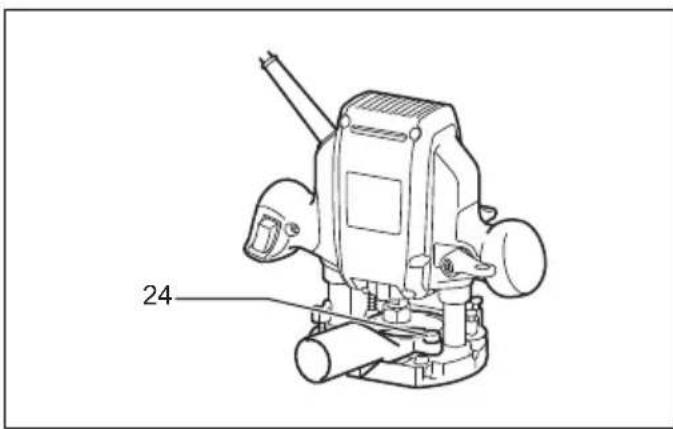
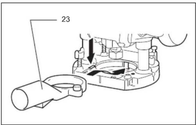
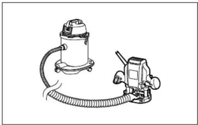
Dust nozzle set (Accessory) (Fig. 15 & 16)
Use the dust nozzle for dust extraction. Install the dust nozzle on the tool base using the thumb screw so that protrusion on the dust nozzle fit to the notch in the tool base.
Then connect a vacuum cleaner to the dust nozzle.
(Fig. 17)
MAINTENANCE
CAUTION:
• Always be sure that the tool is switched off and unplugged before attempting to perform inspection or maintenance.
- Never use gasoline, benzine, thinner, alcohol or the like. Discoloration, deformation or cracks may result. To maintain product SAFETY and RELIABILITY, repairs, any other maintenance or adjustment should be performed by Makita Authorized Service Centers, always using Makita replacement parts.
OPTIONAL ACCESSORIES
CAUTION:
• These accessories or attachments are recommended for use with your Makita tool specified in this manual. The use of any other accessories or attachments might present a risk of injury to persons. Only use accessory or attachment for its stated purpose.
If you need any assistance for more details regarding these accessories, ask your local Makita Service Center.
- Straight & groove forming bits
- Edge forming bits
- Laminate trimming bits
- Straight guide
- Templet guide 25
- Templet guides
- Templet guide adapter
- Lock nut
• Collet cone 3/8", 1/4"
• Collet cone 6 mm, 8 mm - Wrench 13
- Wrench 22
- Dust nozzle set
Router bits
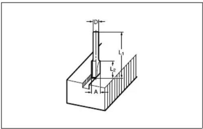
Straight bit (Fig. 18)
mm
| D | A | L | 1 |
| 6 | 20 | 50 | 15 |
| 1/4” | |||
| 8 | 8 | 6 | 0 |
| 6 | 8 | 5 | 0 |
| 1/4” | |||
| 6 | 6 | 5 | 0 |
| 1/4” |
009802
"U" Grooving bit (Fig. 19)
mm
| D | A | L | 1 | L |
| 6 | 6 | 50 | 18 | 3 |
009803
"V" Grooving bit (Fig. 20)
mm
| D | A | L | 1 | L |
| 1/4" | 20 | 50 | 15 | 90° |
009804
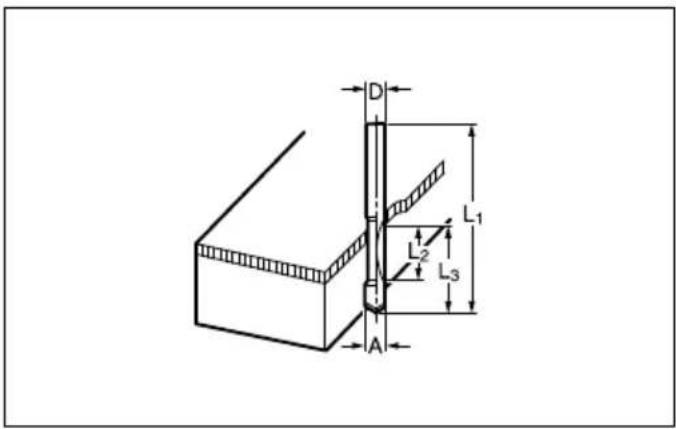
Drill point flush trimming bit (Fig. 21)
mm
| D A L | 1 L 2 L 3 | |||
| 8 | 8 | 60 | 20 | 35 |
| 6 | 6 | 60 | 18 | 28 |
009806
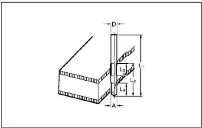
Drill point double flush trimming bit (Fig. 22)
mm
| D A | L 1 | L 2 | L 3 | L 4 | |
| 8 | 8 | 80 | 55 | 20 | 25 |
| 6 | 6 | 70 | 40 | 12 | 14 |
009807
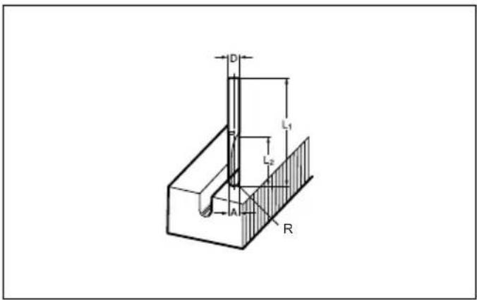
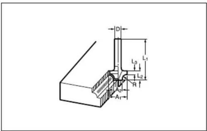
Corner rounding bit (Fig. 23)
mm
| D | A 1 | A 2 | L 1 | L 2 | L 3 | R |
| 6 | 25 | 9 | 48 | 13 | 5 | 8 |
| 6 | 20 | 8 | 45 | 10 | 4 | 4 |
009808
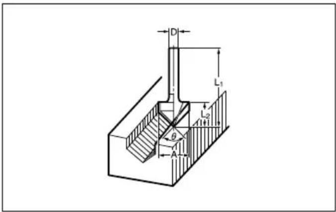
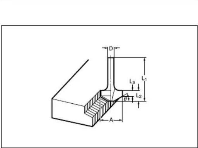
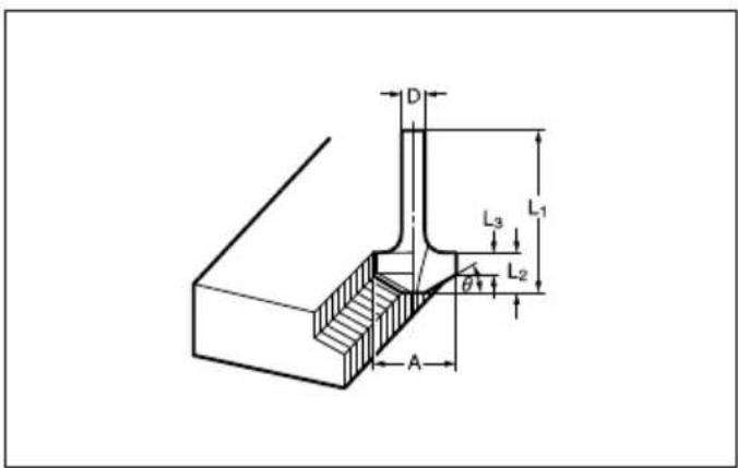
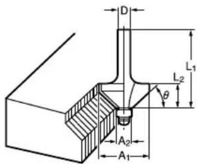
Chamfering bit (Fig. 24)
mm
| D | A | L 1 | L 2 | L 3 | θ |
| 6 | 23 | 46 | 11 | 6 | 30^ |
| 6 | 20 | 50 | 13 | 5 | 45^ |
| 6 | 20 | 49 | 14 | 2 | 60^ |
009809
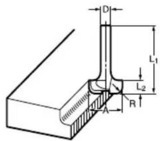
Cove beading bit (Fig. 25)
mm
| D | A | L | 1 | L |
| 6 | 20 | 43 | 8 | 4 |
| 6 | 25 | 48 | 13 | 8 |
009810
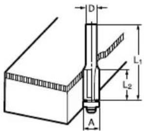
Ball bearing flush trimming bit (Fig. 26)
mm
| D | A | L 1 | L 2 |
| 6 | 10 | 50 | 20 |
| 1/4" |
009811
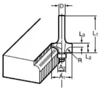
Ball bearing corner rounding bit (Fig. 27)
mm
| D | 0A 1 | A 2 | L 1 | L 2 | L 3 | R |
| 6 | 15 | 8 | 37 | 7 | 3.5 | 3 |
| 6 | 21 | 8 | 40 | 10 | 3.5 | 6 |
| 1/4” |
009812
Ball bearing chamfering bit (Fig. 28)
mm
| D | A 1 | A 2 | L 1 | L 2 | |
| 6 | 26 | 8 | 42 | 12 | 45^ |
| 1/4” | |||||
| 6 | 20 | 8 | 41 | 11 | 60^ |
009813
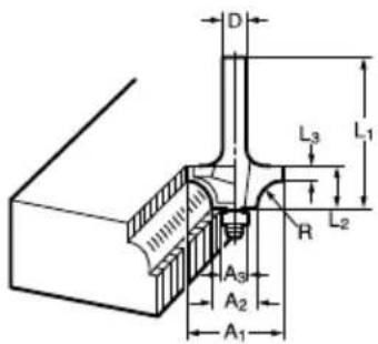
Ball bearing beading bit (Fig. 29)
mm
| D | A 1 | A 2 | A 3 | L 1 | L 2 | L 3 | R |
| 6 | 20 | 12 | 8 | 40 | 10 | 5.5 | 4 |
| 6 | 26 | 12 | 8 | 42 | 12 | 4.5 | 7 |
009814
Ball bearing cove beading bit (Fig. 30)
mm
| D | A 1 | A 2 | A 3 | A 4 | L 1 | L 2 | L 3 | R |
| 6 | 20 | 18 | 12 | 8 | 40 | 10 | 5.5 | 3 |
| 6 | 26 | 22 | 12 | 8 | 42 | 12 | 5 | 5 |
009815
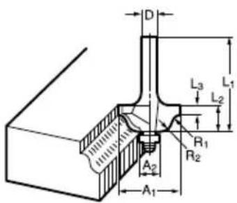
Ball bearing roman ogee bit (Fig. 31)
mm
| D | A 1 | A 2 | L 1 | L 2 | L 3 | R1 | R2 |
| 6 | 20 | 8 | 40 | 10 | 4.5 | 2.5 | 4.5 |
| 6 | 26 | 8 | 42 | 12 | 4.5 | 3 | 6 |
009816
^2 NOTE: R
- Some items in the list may be included in the tool package as standard accessories. They may differ from country to country.
Noise
ENG905-1
The typical A-weighted noise level determined according to EN62841-2-17:
Sound pressure level (LpA): 92 dB (A)
Sound power level ( L_WA ): 100 dB (A)
Uncertainty (K): 3 dB (A)
ENG907-1
- The declared noise emission value(s) has been measured in accordance with a standard test method and may be used for comparing one tool with another.
- The declared noise emission value(s) may also be used in a preliminary assessment of exposure.

WARNING:
- Wear ear protection.
- The noise emission during actual use of the power tool can differ from the declared value(s) depending on the ways in which the tool is used especially what kind of workpiece is processed.
- Be sure to identify safety measures to protect the operator that are based on an estimation of exposure in the actual conditions of use (taking account of all parts of the operating cycle such as the times when the tool is switched off and when it is running idle in addition to the trigger time).
Vibration
ENG900-1
The vibration total value (tri-axial vector sum) determined according to EN62841-2-17:
Work mode: cuttig grooves in MDF
Vibration emission ( a_h ): 4.3 m/s ^2
Uncertainty (K): 1.5 m/s²
ENG901-2
- The declared vibration total value(s) has been measured in accordance with a standard test method and may be used for comparing one tool with another.
- The declared vibration total value(s) may also be used in a preliminary assessment of exposure.

WARNING:
- The vibration emission during actual use of the power tool can differ from the declared value(s) depending on the ways in which the tool is used especially what kind of workpiece is processed.
- Be sure to identify safety measures to protect the operator that are based on an estimation of exposure in the actual conditions of use (taking account of all parts of the operating cycle such as the times when the tool is switched off and when it is running idle in addition to the trigger time).
Declarations of Conformity
For European countries only
The Declarations of conformity are included in Annex A to this instruction manual.