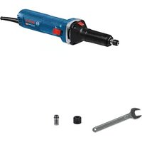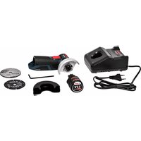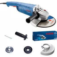
GWS 18 VLI Professional - Coffee grinder BOSCH - Free user manual and instructions
Find the device manual for free GWS 18 VLI Professional BOSCH in PDF.


User questions about GWS 18 VLI Professional BOSCH
0 question about this device. Answer the ones you know or ask your own.
Ask a new question about this device
Download the instructions for your Coffee grinder in PDF format for free! Find your manual GWS 18 VLI Professional - BOSCH and take your electronic device back in hand. On this page are published all the documents necessary for the use of your device. GWS 18 VLI Professional by BOSCH.
USER MANUAL GWS 18 VLI Professional BOSCH
natural_image
3D rendering of a Bosch electric grinder with visible blade and central hub (no text or symbols)- All worklist objects
Dr. Crillnal is letme talimati
English ...... Page 16
Français......Page 25
natural_image
Isometric line drawing of a mechanical housing or enclosure component (no text or symbols)L-BOXX 136
2608438692
natural_image
Technical line drawing of a mechanical housing or bracket component (no text or symbols)2 608 438 098
4

Deutsch
Sicherheitshinweise
natural_image
Diagram of two mechanical components with curved arrows indicating rotation or motion (no text or symbols)natural_image
Diagram of a hand operating a car wheel rim with a rotating wheel (no text or symbols)natural_image
Mechanical assembly diagram showing a rotating motor with directional arrows indicating motion (no text or labels)natural_image
Illustration of a robotic arm with joints and motion arrows indicating movement (no text or symbols)natural_image
Diagram of a mechanical device with rotating components and directional arrows (no text or symbols)www.bosch-pt.com/serviceaddresses
Transport
General Power Tool Safety Warnings
WARNING
Read all safety warnings and all instructions. Failure to follow the
warnings and instructions may result in electric shock, fire and/or serious injury.
Save all warnings and instructions for future reference.
The term "power tool" in the warnings refers to your mains-operated (corded) power tool or battery-operated (cordless) power tool.
Work area safety
▶ Keep work area clean and well lit. Cluttered or dark areas invite accidents.
▶ Do not operate power tools in explosive atmospheres, such as in the presence of flammable liquids, gases or dust. Power tools create sparks which may ignite the dust or fumes.
▶ Keep children and bystanders away while operating a power tool. Distractions can cause you to lose control.
Electrical safety
▶ Power tool plugs must match the outlet. Never modify the plug in any way. Do not use any adapter plugs with earthed (grounded) power tools. Unmodified plugs and matching outlets will reduce risk of electric shock.
▶ Avoid body contact with earthed or grounded surfaces, such as pipes, radiators, ranges and refrigerators. There is an increased risk of electric shock if your body is earthed or grounded.
▶ Do not expose power tools to rain or wet conditions. Water entering a power tool will increase the risk of electric shock.
▶ Do not abuse the cord. Never use the cord for carrying, pulling or unplugging the power tool. Keep cord away from heat, oil, sharp edges or moving parts. Damaged or entangled cords increase the risk of electric shock.
When operating a power tool outdoors, use an extension cord suitable for outdoor use. Use of a cord suitable for outdoor use reduces the risk of electric shock..
▶ If operating a power tool in a damp location is unavoidable, use a residual current device (RCD) protected supply. Use of an RCD reduces the risk of electric shock.
Personal safety
▶ Stay alert, watch what you are doing and use common sense when operating a power tool. Do not use a power tool while you are tired or under the influence of drugs, alcohol or medication. A moment of inattention while operating power tools may result in serious personal injury.
▶ Use personal protective equipment. Always wear eye protection. Protective equipment such as dust mask, non-skid safety shoes, hard hat, or hearing protection used for appropriate conditions will reduce personal injuries.
▶ Prevent unintentional starting. Ensure the switch is in the off-position before connecting to power source and/or battery pack, picking up or carrying the tool.
Carrying power tools with your finger on the switch or energising power tools that have the switch on invites accidents.
Remove any adjusting key or wrench before turning the power tool on. A wrench or a key left attached to a rotating part of the power tool may result in personal injury.
▶ Do not overreach. Keep proper footing and balance at all times. This enables better control of the power tool in unexpected situations.
▶ Dress properly. Do not wear loose clothing or jewellery. Keep your hair, clothing and gloves away from moving parts. Loose clothes, jewellery or long hair can be caught in moving parts.
If devices are provided for the connection of dust extraction and collection facilities, ensure these are connected and properly used. Use of dust collection can reduce dust-related hazards.
Power tool use and care
▶ Do not force the power tool. Use the correct power tool for your application. The correct power tool will do the job better and safer at the rate for which it was designed.
▶ Do not use the power tool if the switch does not turn it on and off. Any power tool that cannot be controlled with the switch is dangerous and must be repaired.
▶ Disconnect the plug from the power source and/or the battery pack from the power tool before making any adjustments, changing accessories, or storing power tools. Such preventive safety measures reduce the risk of starting the power tool accidentally.
▶ Store idle power tools out of the reach of children and do not allow persons unfamiliar with the power tool or these instructions to operate the power tool. Power tools are dangerous in the hands of untrained users.
- Maintain power tools. Check for misalignment or binding of moving parts, breakage of parts and any other condition that may affect the power tool's operation. If damaged, have the power tool repaired before use. Many accidents are caused by poorly maintained power tools.
▶ Keep cutting tools sharp and clean. Properly maintained cutting tools with sharp cutting edges are less likely to bind and are easier to control.
▶ Use the power tool, accessories and tool bits etc. in accordance with these instructions, taking into account the working conditions and the work to be performed. Use of the power tool for operations different from those intended could result in a hazardous situation.
Battery tool use and care
▶ Recharge only with the charger specified by the manufacturer. A charger that is suitable for one type of battery pack may create a risk of fire when used with another battery pack.
▶ Use power tools only with specifically designated battery packs. Use of any other battery packs may create a risk of injury and fire.
When battery pack is not in use, keep it away from other metal objects, like paper clips, coins, keys, nails, screws or other small metal objects, that can make a connection from one terminal to another. Shorting the battery terminals together may cause burns or a fire.
▶ Under abusive conditions, liquid may be ejected from the battery; avoid contact. If contact accidentally occurs, flush with water. If liquid contacts eyes, additionally seek medical help. Liquid ejected from the battery may cause irritation or burns.
Service
▶ Have your power tool serviced by a qualified repair person using only identical replacement parts. This will ensure that the safety of the power tool is maintained.
Safety information for the angle grinder
Safety Warnings common for Grinding, Sanding, Wire Brushing or Abrasive Cutting Off operations
This power tool is intended to function as a grinder, sander, wire brush or cut-off tool. Read all safety warnings, instructions, illustrations and specifications provided with this power tool. Failure to follow all instructions listed below may result in electric shock, fire and/or serious injury.
▶ Operations such as polishing are not recommended to be performed with this power tool. Operations for which the power tool was not designed may create a hazard and cause personal injury.
▶ Do not use accessories which are not specifically designed and recommended by the tool manufacturer. Just because the accessory can be attached to your power tool, it does not assure safe operation.
The rated speed of the accessory must be at least equal to the maximum speed marked on the power tool. Accessories running faster than their rated speed can break and fly apart.
The outside diameter and the thickness of your accessory must be within the capacity rating of your
power tool. Incorrectly sized accessories cannot be adequately guarded or controlled.
Threaded mounting of accessories must match the grinder spindle thread. For accessories mounted by flanges, the arbour hole of the accessory must fit the locating diameter of the flange. Accessories that do not match the mounting hardware of the power tool will run out of balance, vibrate excessively and may cause loss of control.
Do not use a damaged accessory. Before each use inspect the accessory such as abrasive wheels for chips and cracks, backing pad for cracks, tear or excess wear, wire brush for loose or cracked wires. If power tool or accessory is dropped, inspect for damage or install an undamaged accessory. After inspecting and installing an accessory, position yourself and bystanders away from the plane of the rotating accessory and run the power tool at maximum no load speed for one minute. Damaged accessories will normally break apart during this test time.
▶ Wear personal protective equipment. Depending on application, use face shield, safety goggles or safety glasses. As appropriate, wear dust mask, hearing protectors, gloves and workshop apron capable of stopping small abrasive or workpiece fragments. The eye protection must be capable of stopping flying debris generated by various operations. The dust mask or respirator must be capable of filtrating particles generated by your operation. Prolonged exposure to high intensity noise may cause hearing loss.
▶ Keep bystanders a safe distance away from work area. Anyone entering the work area must wear personal protective equipment. Fragments of workpiece or of a broken accessory may fly away and cause injury beyond immediate area of operation.
▶ Hold the power tool by insulated gripping surfaces only, when performing an operation where the cutting accessory may contact hidden wiring. Cutting accessory contacting a "live" wire may make exposed metal parts of the power tool "live" and could give the operator an electric shock.
▶ Never lay the power tool down until the accessory has come to a complete stop. The spinning accessory may grab the surface and pull the power tool out of your control.
▶ Do not run the power tool while carrying it at your side. Accidental contact with the spinning accessory could snag your clothing, pulling the accessory into your body.
Regularly clean the power tool's air vents. The motor's fan will draw the dust inside the housing and excessive accumulation of powdered metal may cause electrical hazards.
▶ Do not operate the power tool near flammable materials. Sparks could ignite these materials.
18 | English
▶ Do not use accessories that require liquid coolants. Using water or other liquid coolants may result in electrocution or shock.
Kickback and Related Warnings
Kickback is a sudden reaction to a pinched or snagged rotating wheel, backing pad, brush or any other accessory. Pinching or snagging causes rapid stalling of the rotating accessory which in turn causes the uncontrolled power tool to be forced in the direction opposite of the accessory's rotation at the point of the binding.
For example, if an abrasive wheel is snagged or pinched by the workpiece, the edge of the wheel that is entering into the pinch point can dig into the surface of the material causing the wheel to climb out or kick out. The wheel may either jump toward or away from the operator, depending on direction of the wheel's movement at the point of pinching. Abrasive wheels may also break under these conditions. Kickback is the result of power tool misuse and/or incorrect operating procedures or conditions and can be avoided by taking proper precautions as given below.
Maintain a firm grip on the power tool and position your body and arm to allow you to resist kickback forces. Always use auxiliary handle, if provided, for maximum control over kickback or torque reaction during start-up. The operator can control torque reactions or kickback forces, if proper precautions are taken.
▶ Never place your hand near the rotating accessory. Accessory may kickback over your hand.
Do not position your body in the area where power tool will move if kickback occurs. Kickback will propel the tool in direction opposite to the wheel's movement at the point of snagging.
▶ Use special care when working corners, sharp edges etc. Avoid bouncing and snagging the accessory. Corners, sharp edges or bouncing have a tendency to snag the rotating accessory and cause loss of control or kickback.
▶ Do not attach a saw chain woodcarving blade or toothed saw blade. Such blades create frequent kickback and loss of control.
Safety Warnings specific for Grinding and Abrasive Cutting-Off operations
▶ Use only wheel types that are recommended for your power tool and the specific guard designed for the selected wheel. Wheels for which the power tool was not designed cannot be adequately guarded and are unsafe.
The grinding surface of centre depressed wheels must be mounted below the plane of the guard lip. An improperly mounted wheel that projects through the plane of the guard lip cannot be adequately protected.
The guard must be securely attached to the power tool and positioned for maximum safety, so the least amount of wheel is exposed towards the operator.
The guard helps to protect operator from broken wheel fragments, accidental contact with wheel and sparks that could ignite clothing.
▶ Wheels must be used only for recommended applications. For example: do not grind with the side of cut-off wheel. Abrasive cut-off wheels are intended for peripheral grinding, side forces applied to these wheels may cause them to shatter.
▶ Always use undamaged wheel flanges that are of correct size and shape for your selected wheel. Proper wheel flanges support the wheel thus reducing the possibility of wheel breakage. Flanges for cut-off wheels may be different from grinding wheel flanges.
▶ Do not use worn down wheels from larger power tools. Wheel intended for larger power tool is not suitable for the higher speed of a smaller tool and may burst.
Additional Safety Warnings specific for Abrasive Cutting Off operations
Do not "jam" the cut-off wheel or apply excessive pressure. Do not attempt to make an excessive depth of cut. Overstressing the wheel increases the loading and susceptibility to twisting or binding of the wheel in the cut and the possibility of kickback or wheel breakage.
▶ Do not position your body in line with and behind the rotating wheel. When the wheel, at the point of operation, is moving away from your body, the possible kick-back may propel the spinning wheel and the power tool directly at you.
When wheel is binding or when interrupting a cut for any reason, switch off the power tool and hold the power tool motionless until the wheel comes to a complete stop. Never attempt to remove the cut-off wheel from the cut while the wheel is in motion otherwise kickback may occur. Investigate and take corrective action to eliminate the cause of wheel binding.
▶ Do not restart the cutting operation in the workpiece. Let the wheel reach full speed and carefully re-enter the cut. The wheel may bind, walk up or kickback if the power tool is restarted in the workpiece.
▶ Support panels or any oversized workpiece to minimize the risk of wheel pinching and kickback. Large workpieces tend to sag under their own weight. Supports must be placed under the workpiece near the line of cut and near the edge of the workpiece on both sides of the wheel.
▶ Use extra caution when making a "pocket cut" into existing walls or other blind areas. The protruding wheel may cut gas or water pipes, electrical wiring or objects that can cause kickback.
Safety Warnings specific for Sanding operations
▶ Do not use excessively oversized sanding disc paper. Follow manufacturers recommendations, when selecting sanding paper. Larger sanding paper extending beyond the sanding pad presents a laceration hazard and may cause snagging, tearing of the disc, or kickback.
Safety Warnings specific for Wire Brushing operations
▶ Be aware that wire bristles are thrown by the brush even during ordinary operation. Do not overstress the
wires by applying excessive load to the brush The wire bristles can easily penetrate light clothing and/or skin.
If the use of a guard is recommended for wire brushing, do not allow any interference of the wire wheel or brush with the guard. Wire wheel or brush may expand in diameter due to work load and centrifugal forces.
Additional safety information

Wear safety goggles.
▶ Use suitable detectors to determine if there are hidden supply lines or contact the local utility company for assistance. Contact with electric cables can cause fire and electric shock. Damaging gas lines can lead to explosion. Breaking water pipes causes property damage.
▶ Do not touch grinding and cutting discs until they have cooled down. The discs can become very hot while working.
▶ Release the On/Off switch and set it to the Off position when the power supply is interrupted, e.g. when the battery pack is removed. This prevents uncontrolled restarting.
- Secure the workpiece. A workpiece clamped with clamping devices or in a vice is held more secure than by hand.
In case of damage and improper use of the battery, vapours may be emitted. The battery can set alight or explode. Ensure the area is well ventilated and seek medical attention should you experience any adverse effects. The vapours may irritate the respiratory system.
▶ Do not open the battery. There is a risk of short-circuiting.
The battery can be damaged by pointed objects such as nails or screwdrivers or by force applied externally. An internal short circuit may occur, causing the battery to burn, smoke, explode or overheat.
▶ Only use the battery with products from the manufacturer. This is the only way in which you can protect the battery against dangerous overload.

Protect the battery against heat, e.g. against continuous intense sunlight, fire, dirt, water and moisture. There is a risk of explosion and short-circuiting.
Product Description and Specifications

Read all the safety and general instructions.
Failure to observe the safety and general instructions may result in electric shock, fire and/or serious injury.
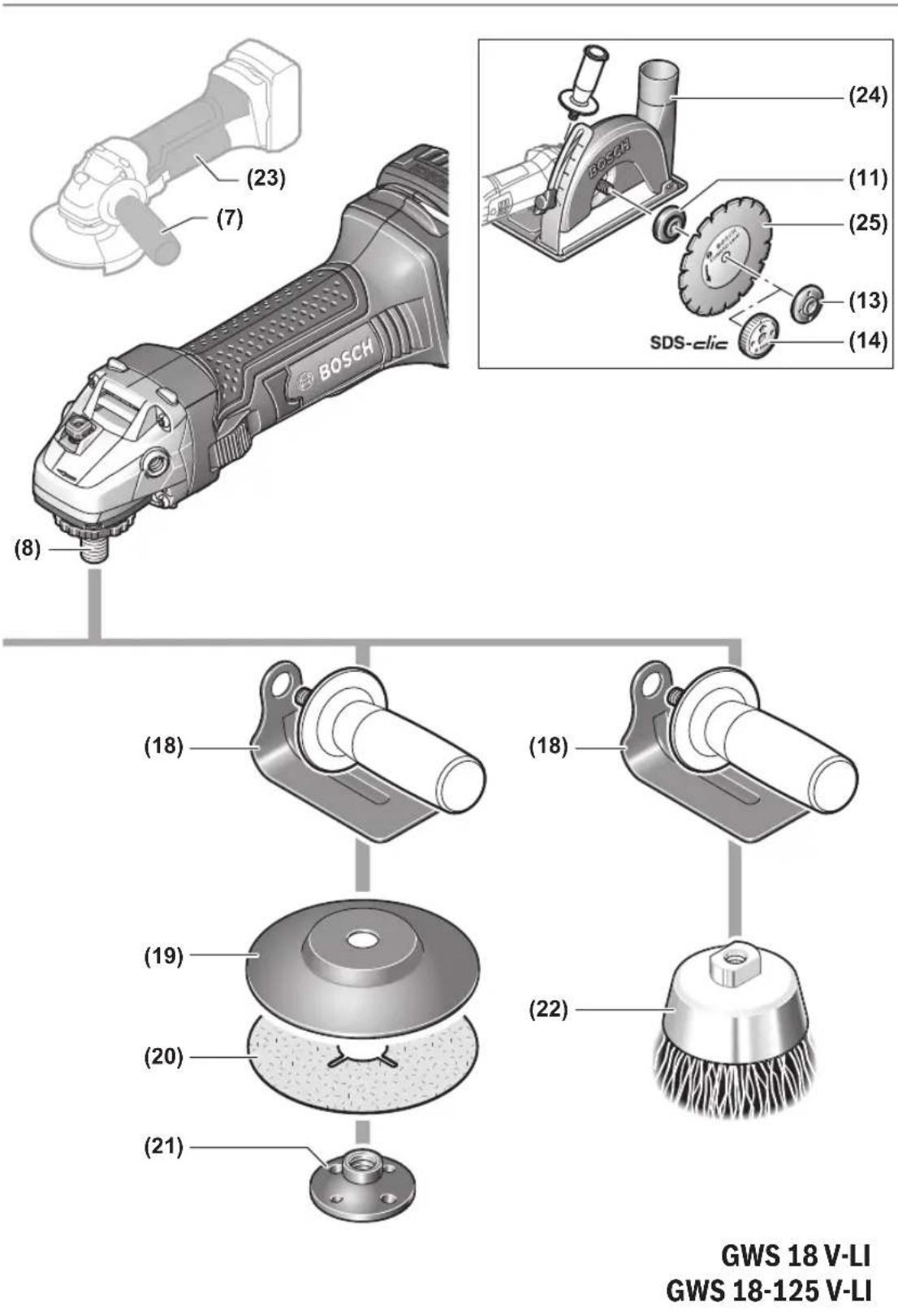
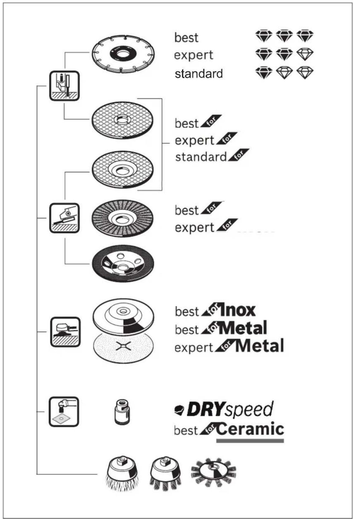
Please observe the illustrations at the beginning of this operating manual.
Intended use
The power tool is intended for cutting, roughing and brushing metal and stone materials without the use of water.
A special protective guard for cutting must be used when cutting bonded abrasives.
Sufficient dust extraction must be provided when cutting stone.
With approved abrasive tools, the power tool can be used for sanding with sanding discs.
Product Features
The numbering of the product features refers to the diagram of the power tool on the graphics page.
(1) Direction of rotation arrow on housing
(2) Spindle lock button
(3) On/off switch
(4) Hex key
(5) Battery ^4
(6) Battery release button A)
(7) Auxiliary handle (insulated gripping surface)
(8) Grinding spindle
(9) Locking screw for protective guard
(10) Protective guard for grinding
(11) Mounting flange with O-ring
(12) Grinding disc ^A)
(13) Clamping nut
(14) Quick-clamping nut SDS-clic ^A)
(15) Carbide grinding head ^4
(16) Protective guard for cutting ^4
(17) Cutting disc ^A)
(18) Hand guard ^A)
(19) Rubber sanding pad ^(4)
(20) Abrasive disc ^A)
(21) Round nut ^A)
(22) Cup brush ^A)
(23) Handle (insulated gripping surface)
(24) Extraction guard for cutting with a guide block ^4
(25) Diamond cutting disc ^A)
A) Accessories shown or described are not included with the product as standard. You can find the complete selection of accessories in our accessories range.
20 | English
Technical Data
| Angle grinder GWS 18 V-LI GWS 18V-125 V-LI | ||
| Article number | 3 601 J3A 300 3 601 J3A 301 | |
| Rated voltage V= 18 18 | ||
| Rated speed ^A) | min ^-1 | 11,000 11,000 |
| Max. grinding disc diameter mm 115 125 | ||
| Grinding spindle thread M 14 M 14 | ||
| Max. thread length of grinding spindle mm 22 22 | ||
| Weight according to EPTA-Procedure 01:2014 ^B) | kg 2.0–3.0 2.0–3.0 | |
| Recommended ambient temperature during charging °C 0 to +35 0 to +35 | ||
| Permitted ambient temperature during operation ^(c) and during storage | °C –20 to +50 –20 to +50 | |
| Recommended rechargeable batteries GBA 18V... | ProCORE18V... | GBA 18V...ProCORE18V... |
| Recommended battery chargers GAL 18... | GAX 18...GAL 36... | GAL 18...GAX 18...GAL 36... |
A) Rated speed in accordance with EN 60745-2-3
B) Depends on battery in use
C) Limited performance at temperatures <0 °C
Noise/Vibration Information
Noise emission values determined according to EN 60745-2-3.
Typically the A-weighted noise level of the power tool are: 82 dB(A); sound power level 93 dB(A). Uncertainty K = 3 dB.
Wear hearing protection!
Vibration total values a_1 (triax vector sum) and uncertainty K determined according to EN 60745-2-3:
Surface grinding (roughing):
$$ a _ {n} = 6. 0 \mathrm{m} / \mathrm{s} ^ {2}, K = 1. 5 \mathrm{m} / \mathrm{s} ^ {2}, $$
Disc sanding:
$$ a _ {n} = 2. 5 \mathrm{m} / \mathrm{s} ^ {2}, K = 1. 5 \mathrm{m} / \mathrm{s} ^ {2}. $$
The vibration level given in these instructions has been measured in accordance with a standardised measuring procedure and may be used to compare power tools. It can also be used for a preliminary estimation of exposure to vibration.
The stated vibration level applies to the main applications of the power tool. However, if the power tool is used for different applications, with different application tools or poorly maintained, the vibration level may differ. This can significantly increase the exposure to vibration over the total working period.
To estimate the exposure to vibration accurately, the times when the tool is switched off or when it is running but not actually being used should also be taken into account. This can significantly reduce the exposure to vibration over the total working period.
Implement additional safety measures to protect the operator from the effects of vibration, such as servicing the power tool and application tools, keeping the hands warm, and organising workflows correctly.
Fitting
Charging the battery
▶ Use only the chargers listed in the technical data. Only these chargers are matched to the lithium-ion battery of your power tool.
Note: The battery is supplied partially charged. To ensure full battery capacity, fully charge the battery in the charger before using your power tool for the first time.
The lithium-ion battery can be charged at any time without reducing its service life. Interrupting the charging process does not damage the battery.
The lithium-ion battery is protected against deep discharge by the "Electronic Cell Protection (ECP)". When the battery is discharged, the power tool is switched off by means of a protective circuit: The application tool no longer rotates.
▶ Do not continue to press the On/Off switch after the power tool has automatically switched off. The battery can be damaged.
Follow the instructions on correct disposal.
Removing the Battery
The battery (5) is equipped with two locking levels to prevent the battery from falling out if the battery release button (6) is pressed unintentionally. As long as the battery is inserted in the power tool, it is held in position by means of a spring.
To remove the battery (5), press the release button (6) and pull the battery out of the power tool. Do not use force to do this.
Battery charge indicator
The green LEDs on the battery charge indicator indicate the state of charge of the battery. For safety reasons, it is only possible to check the state of charge when the power tool is not in operation.
Press the button for the battery charge indicator 📄 or 📋 show the state of charge. This is also possible when the battery is removed.
If no LED lights up after pressing the button for the battery charge indicator, then the battery is defective and must be replaced.
Battery model GBA 18V...


LEDs Capacity
3× continuous green light 60–100%
2× continuous green light 30–60 %
1× continuous green light 5–30%
1× flashing green light 0–5 %
Battery model ProCORE18V...


LEDs Capacity
5× continuous green light 80-100%
4× continuous green light 60–80 %
3× continuous green light 40–60 %
2× continuous green light 20-40%
1× continuous green light 5–20%
1× flashing green light 0–5 %
Fitting protective equipment
Remove the battery from the power tool before carrying out work on the power tool (e.g. maintenance, changing tool, etc.). The battery should also be removed for transport and storage. There is risk of injury from unintentionally pressing the on/off switch.
Note: If the grinding disc breaks during operation or the holding fixtures on the protective guard/power tool become damaged, the power tool must be sent to the after-sales service immediately; see the "After-Sales Service and Application Service" section for addresses.
Protective guard for grinding

natural_image
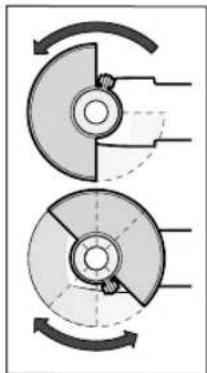
Diagram of two mechanical components with curved arrows indicating rotation or motion (no text or symbols)Place the protective guard (10) on the spindle collar. Adjust the position of the protective guard (10) to meet the requirements of the operation. Lock the protective guard (10) by tightening the locking screw (9) using the hex key (4).
▶ Adjust the protective guard (10) such that sparking in the direction of the operator is prevented.
Note: The coding cams on the protective guard (10) ensure that only a protective guard that is suitable for the power tool can be fitted.
Protective guard for cutting
▶ Always use the protective guard for cutting (16) when cutting bonded abrasives.
▶ Provide sufficient dust extraction when cutting stone.
The protective guard for cutting (16) is fitted in the same way as the protective guard for grinding (10).
Extraction guard for cutting with a guide block
The extraction guard for cutting with a guide block (24) is fitted in the same way as the protective guard for grinding (10).
Side handle
▶ Do not operate your power tool without the side handle (7).
Screw the side handle (7) on the left or right of the machine head depending on how your are working.
Hand guard
▶ Always fit the hand guard (18) when working with the rubber sanding plate (19) or with the cup brush/disc brush/flap disc.
Attach the hand guard (18) to the side handle (7).
Fitting the abrasive tools
Remove the battery from the power tool before carrying out work on the power tool (e.g. maintenance, changing tool, etc.). The battery should also be removed for transport and storage. There is risk of injury from unintentionally pressing the on/off switch.
▶ Do not touch grinding and cutting discs until they have cooled down. The discs can become very hot while working.
Clean the grinding spindle (8) and all the parts to be fitted. Lock the grinding spindle with the spindle lock button (2) before clamping and releasing the abrasive tools.
22 | English
▶ Do not press the spindle lock button while the grinding spindle is moving. The power tool may become damaged if you do this.
Grinding/cutting disc
Pay attention to the dimensions of the abrasive tools. The diameter of the hole must match that of the mounting flange. Do not use an adapter or reducer.
When using diamond cutting discs, ensure that the arrow indicating the direction of rotation on the diamond cutting disc matches the direction of rotation of the power tool (see the direction of rotation arrow on the machine head).
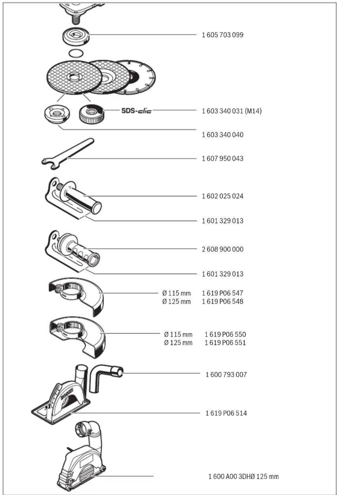
See the graphics page for assembly instructions.
To fasten the grinding/cutting disc, screw on the clamping nut (13) and tighten with the two-hole spanner (see "Quick-clamping nut" page etc.)
▶ After fitting the abrasive tool, check that the abrasive tool is fitted correctly and can turn freely before switching on the power tool. Make sure that the abrasive tool does not brush against the protective guard or other parts.
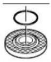
A plastic part (O-ring) is fitted around the cent-ring collar in the mounting flange (11). If the O-ring is missing or damaged, the mounting flange (11) must be replaced before operation can resume.
Flap disc
▶ Always fit the hand guard (18) when working with the flap disc.
Rubber sanding pad
▶ Always fit the hand guard (18) when working with the rubber sanding pad (19).
See the graphics page for fitting instructions.
Screw on the round nut (21) and tighten with the two-pin spanner.
Cup brush/disc brush
▶ Always fit the hand guard (18) when working with the cup brush or disc brush.
See the graphics page for fitting instructions.
The cup brush/disc brush must be screwed onto the grinding spindle until it rests firmly against the grinding spindle flange at the end of the grinding spindle thread. Tighten the cup brush/disc brush with an open-ended spanner.
Quick-clamping nut SDS-clic
To change the abrasive tool easily without having to use any additional tools, you can use the quick-clamping nut (14) instead of the clamping nut (13).
▶ The quick-clamping nut (14) may be used only for grinding or cutting discs.
Only use quick-clamping nuts (14) that are in good working order and not damaged.
When screwing on, make sure that the printed side of the quick-clamping nut (14) is not facing the grinding disc; the arrow must be pointing towards the index mark (26).

text_image
(26)Press the spindle lock button (2) to lock the grinding spindle. To tighten the quick-clamping nut, turn the grinding disc firmly clockwise.

natural_image
Diagram of a hand operating a mechanical disc with rotating wheel and base plate (no text or symbols)If the quick-clamping nut has been attached correctly and is not damaged, you can loosen it by hand by turning the knurled ring anticlockwise. If the quick-clamping nut is stuck, do not attempt to loosen it with pliers – always use the two-pin spanner. Position the two-pin spanner as shown in the figure.
Approved abrasive tools
You can use all the abrasive tools mentioned in these operating instructions.
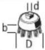
The permissible speed [min^-1] or the circumferential speed [m/s] of the abrasive tools used must at least match the values given in the table.
It is therefore important to observe the permissible rotational/circumferential speed on the label of the abrasive tool.
| Max. [mm] [mm] | |||||
| D b d [min] | ^-1 [m/s] | ||||
| 115 | 7 | 22.2 | 11,000 | 80 | |
| 125 | 7 | 22.2 | 11,000 | 80 | |
| 115 | - | - | 11,000 | 80 | |
| 125 | - | - | 11,000 | 80 | |
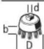
75 30 M 14 11,000 45
Rotating the machine head
Remove the battery from the power tool before carrying out work on the power tool (e.g. maintenance, changing tool, etc.). The battery should also be removed for transport and storage. There is risk of injury from unintentionally pressing the on/off switch.

natural_image
Mechanical assembly diagram showing rotational components and motion arrows (no text or labels)The machine head can be rotated in 90° increments. In this way, the on/off switch can be brought into a more favourable handling position for particular applications, e.g. for left-handed tool users. Completely unscrew the four screws. Rotate the ma-
chine head carefully, without removing it from the housing, into the new position. Screw in and retighten the four screws.
Dust/Chip Extraction
Dust from materials such as lead-containing coatings, some wood types, minerals and metal can be harmful to one's health. Touching or breathing-in the dust can cause allergic reactions and/or lead to respiratory infections of the user or bystanders.
Certain dust, such as oak or beech dust, is considered carcinogenic, especially in connection with wood-treatment additives (chromate, wood preservative). Materials containing asbestos may only be worked by specialists.
- Provide for good ventilation of the working place.
- It is recommended to wear a P2 filter-class respirator.
Observe the relevant regulations in your country for the materials to be worked.
- Avoid dust accumulation at the workplace. Dust can easily ignite.
Operation
Start-up
Inserting the battery
Push the charged battery (5) into the base of the power tool from the front until the battery is securely locked.
Switching on/off
To start the power tool, push the on/off switch (3) forward. To lock the on/off switch (3) in position, push the on/off switch (3) forward and down until it clicks into place. To switch off the power tool, release the on/off switch (3); or, if the switch is locked, briefly push the on/off switch (3) backward and down and then release it.
▶ Always check abrasive tools before using them. The abrasive tool must be fitted properly and be able to move freely. Carry out a test run for at least one minute with no load. Do not use abrasive tools that are damaged, run untrue or vibrate during use. Damaged abrasive tools can burst apart and cause injuries.
Working advice
▶ Exercise caution when cutting slots in structural walls; see the "Information on structural design" section.
▶ Clamp the workpiece if it is not secure under its own weight.
▶ Do not load the power tool so heavily that it comes to a stop.
▶ If the power tool has been subjected to a heavy load, continue to run it at no-load for several minutes to cool down the accessory.
▶ Do not use the power tool with a cut-off stand.
If the power tool becomes electrostatically charged, the built-in electronics will switch the power tool off. Press the on/off switch (3) again to restart the power tool.
▶ Do not touch grinding and cutting discs until they have cooled down. The discs can become very hot while working.
Rough grinding
▶ Never use cutting discs for rough grinding.
The best rough grinding results are achieved with a set angle of 30^ to 40^ . Move the power tool back and forth with moderate pressure. This will ensure that the workpiece does not become too hot or discolour and that grooves are not formed.
Flap Disc
With the flap disc (accessory), curved surfaces and profiles can be worked. Flap discs have a considerably higher service life, lower noise levels and lower sanding temperatures than conventional sanding sheets.
Cutting Metal
▶ Always use the protective guard for cutting (16) when cutting bonded abrasives.
When carrying out abrasive cutting, use a moderate feed that is suited to the material being machined. Do not exert pressure on the cutting disc and do not tilt or swing the power tool.
Do not attempt to reduce the speed of a cutting disc coming to a stop by applying pressure from the side.
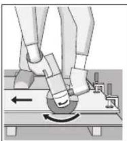
natural_image
Illustration of a robotic arm with motion arrows indicating movement (no text or symbols)The power tool must always work in an up-grinding motion. Otherwise, there is a risk that it will be pushed uncontrolled out of the cut. For best results when cutting profiles and rectangular tubing, start at the smallest cross section.
Cutting stone
▶ Provide sufficient dust extraction when cutting stone.
▶ Wear a dust mask.
The power tool may be used only for dry cutting/grinding.
For best results when cutting stone, use a diamond cutting disc.
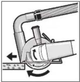
When using the extraction guard for cutting with a guide block (24), the vacuum cleaner must be approved for vacu-
24 | English
uming stone dust. Suitable vacuum cleaners are available from Bosch.
natural_image
Diagram of a mechanical device with rotating components and directional arrows (no text or symbols)Switch on the power tool and position it with the front part of the guide block on the workpiece. Move the power tool with a moderate feed motion that is suited to the material being machined.
When cutting especially hard materials such as con-
crete with a high pebble content, the diamond cutting disc can overheat and become damaged as a result. This is clearly indicated by circular sparking, rotating with the diamond cutting disc.
If this happens, stop cutting and allow the diamond cutting disc to cool down by running the power tool for a short time at maximum speed with no load.
Working noticeably slower and with circular sparking indicate that the diamond cutting disc that has become dull. You can resharpen the disc by briefly cutting into abrasive material (e.g. lime-sand brick).
Information on structural design
Slots in load-bearing walls are subject to DIN 1053 part 1 or country-specific regulations. These regulations must be observed under all circumstances. Seek advice from the responsible structural engineer, architect or construction supervisor before starting work.
Recommendations for optimal handling of the battery
Protect the battery against moisture and water.
Only store the battery only within a temperature range of -20 to 50 °C. Do not leave the battery in your car in the summer, for example.
Occasionally clean the ventilation slots on the battery using a soft brush that is clean and dry.
A significantly reduced operating time after charging indicates that the battery has deteriorated and must be replaced.
Follow the instructions on correct disposal.
Maintenance and Service
Maintenance and Cleaning
Remove the battery from the power tool before carrying out work on the power tool (e.g. maintenance, changing tool, etc.). The battery should also be removed for transport and storage. There is risk of injury from unintentionally pressing the on/off switch.
▶ To ensure safe and efficient operation, always keep the power tool and the ventilation slots clean.
Store and handle the accessories carefully.
After-Sales Service and Application Service
Our after-sales service responds to your questions concerning maintenance and repair of your product as well as spare parts. You can find explosion drawings and information on spare parts at: www.bosch-pt.com
The Bosch product use advice team will be happy to help you with any questions about our products and their accessories.
In all correspondence and spare parts orders, please always include the 10-digit article number given on the nameplate of the product.
Great Britain
Robert Bosch Ltd. (B.S.C.)
P.O. Box 98
Broadwater Park
North Orbital Road
Denham Uxbridge
UB 9 5HJ
At www.bosch-pt.co.uk you can order spare parts or arrange the collection of a product in need of servicing or repair.
Tel. Service: (0344) 7360109
E-Mail: boschservicecentre@bosch.com
You can find further service addresses at:
www.bosch-pt.com/serviceaddresses
Transport
The contained lithium-ion batteries are subject to the Dangerous Goods Legislation requirements. The batteries are suitable for road-transport by the user without further restrictions.
When shipping by third parties (e.g.: by air transport or forwarding agency), special requirements on packaging and labelling must be observed. For preparation of the item being shipped, consulting an expert for hazardous material is required.
Dispatch battery packs only when the housing is undamaged. Tape or mask off open contacts and pack up the battery in such a manner that it cannot move around in the packaging. Please also observe the possibility of more detailed national regulations.
Disposal

Power tools, rechargeable batteries, accessories and packaging should be sorted for environmental-friendly recycling.

Do not dispose of power tools and batteries/rechargeable batteries into household waste!
Only for EU countries:
According to the Directive 2012/19/EU, power tools that are no longer usable, and according to the Directive 2006/66/EC, defective or used battery packs/batteries, must be collected separately and disposed of in an environmentally correct manner.
Battery packs/batteries:
Li-ion:
Please observe the notes in the section on transport (see "Transport", page 24).
Français
natural_image
Mechanical diagram showing two rotating components with curved arrows indicating rotation direction (no text or symbols)natural_image
Diagram of a hand pressing a circular component on a textured circular base, with no visible text or symbols.natural_image
Mechanical assembly diagram showing a rotating component with arrows indicating motion (no text or symbols)natural_image
Illustration of a robotic arm with motion arrows indicating movement (no text or symbols)natural_image
Diagram of a mechanical device with rotating components and directional arrows (no text or symbols)Robert Bosch (France) S.A.S.
www.bosch-pt.com/serviceaddresses
Transport
natural_image
Mechanical diagram showing two rotating components with curved arrows indicating rotation direction (no text or symbols)natural_image
Diagram of a hand operating a mechanical component with a rotating arrow (no text or symbols)natural_image
Mechanical assembly diagram showing a rotating motor with directional arrows indicating motion (no text or symbols)natural_image
Illustration of a robotic arm with joints and motion arrows indicating movement (no text or symbols)natural_image
Mechanical diagram showing a tool interacting with a curved pipe and fan (no text or symbols)www.bosch-pt.com/serviceaddresses
Transporte
natural_image
Mechanical diagram showing two circular components with curved arrows indicating rotation or motion (no text or symbols)Montar as ferramentas de lixar
natural_image
Diagram of a hand operating a mechanical component with a rotating arrow (no text or symbols)natural_image
Mechanical assembly diagram showing rotational components and motion arrows (no text or labels)natural_image
Illustration of a robotic arm performing a circular motion on a platform, with no visible text or symbols.natural_image
Mechanical diagram showing a tool interacting with a curved pipe and fan (no text or symbols)www.bosch-pt.com/serviceaddresses
Transporte
natural_image
Diagram of two mechanical components with curved arrows indicating rotation or motion (no text or symbols)natural_image
Diagram of a hand operating a mechanical disc with a rotating knob (no text or symbols)natural_image
Mechanical assembly diagram showing a gear and rotor mechanism with rotational arrows (no text or labels)natural_image
Illustration of a robotic arm interacting with a circular mechanical component, showing motion direction (no text or symbols)natural_image
Diagram of a mechanical device with rotating components and directional arrows (no text or symbols)natural_image
Mechanical diagram showing two rotating components with curved arrows indicating rotation direction (no text or symbols)Snelspanmoer SDS-clic
natural_image
Diagram of a hand operating a mechanical component with a rotating arrow (no text or symbols)natural_image
Mechanical assembly diagram showing rotational components and motion arrows (no text or labels)natural_image
Illustration of a robotic arm performing a circular motion maneuver on a platform (no text or symbols)natural_image
Mechanical diagram showing a tool interacting with a rotating device (no text or symbols visible)www.bosch-pt.com/serviceaddresses
Vervoer
natural_image
Mechanical diagram showing two rotating components with curved arrows indicating rotation direction (no text or symbols)natural_image
Diagram of a hand operating a mechanical disc with a rotating wheel (no text or symbols)natural_image
Mechanical assembly diagram showing a rotating component with arrows indicating motion (no text or symbols)natural_image
Illustration of a robotic arm interacting with a ball on a platform, showing motion direction (no text or symbols)natural_image
Diagram of a mechanical device with rotating components and directional arrows (no text or symbols)Bosch Service Center
Telegrafvej 3
2750 Ballerup
På www.bosch-pt.dk kan der online bestilles reservedele eller oprettes en reparations ordre.
Tlf. Service Center: 44898855
Fax: 44898755
E-Mail: vaerktoej@dk.bosch.com
www.bosch-pt.com/serviceaddresses
Transport
natural_image
Diagram of two mechanical components with curved arrows indicating rotation or motion (no text or symbols)natural_image
Diagram of a hand operating a mechanical component with a rotating arrow and directional arrow (no text or symbols)natural_image
Mechanical assembly diagram showing rotational components and motion arrows (no text or labels)natural_image
Illustration of a robotic arm with a circular motion arrow indicating rotational movement (no text or symbols present)natural_image
Diagram of a mechanical device with rotating components and directional arrows (no text or symbols)Bosch Service Center
Telegrafvej 3
2750 Ballerup
Danmark
Tel.: (08) 7501820 (inom Sverige)
Fax: (011) 187691
www.bosch-pt.com/serviceaddresses
Transport
Overflatesliping (skrubbing):
$$ a _ {n} = 6, 0 \mathrm{m} / \mathrm{s} ^ {2}, K = 1, 5 \mathrm{m} / \mathrm{s} ^ {2}, $$
Sliping med slipeskive:
$$ a _ {n} = 2, 5 \mathrm{m} / \mathrm{s} ^ {2}, K = 1, 5 \mathrm{m} / \mathrm{s} ^ {2}. $$
Vernedeksel for slipping
natural_image
Mechanical diagram showing two rotating components with curved arrows indicating rotation direction (no text or symbols)natural_image
Diagram of a hand operating a mechanical disc with a rotating wheel (no text or symbols)natural_image
Mechanical assembly diagram showing rotational components and motion arrows (no text or labels)natural_image
Illustration of a robotic arm with motion arrows indicating movement (no text or symbols)natural_image
Diagram of a mechanical device with rotating components and directional arrows (no text or symbols)www.bosch-pt.com/serviceaddresses
Transport
natural_image
Diagram of two mechanical components with curved arrows indicating rotation or motion (no text or symbols)natural_image
Diagram of a hand operating a mechanical component with a rotating arrow (no text or symbols)natural_image
Mechanical assembly diagram showing rotational motion with no text or symbolsnatural_image
Illustration of a robotic arm with motion arrows indicating movement (no text or symbols)natural_image
Mechanical diagram showing a tool interacting with a curved pipe and rotating component (no text or symbols)www.bosch-pt.com/serviceaddresses
Kuljetus
natural_image
Mechanical diagram showing two rotating components with curved arrows indicating rotation direction (no text or symbols)natural_image
Diagram of a hand operating a mechanical disc with a rotating knob (no text or symbols)natural_image
Mechanical assembly diagram showing a rotating component with directional arrows indicating motion (no text or symbols)natural_image
Illustration of a robotic arm with a rotating head and mechanical components (no text or symbols)natural_image
Mechanical diagram showing a pipe clamp and rotating component (no text or symbols)www.bosch-pt.com/serviceaddresses
Μεταφορά
natural_image
Mechanical diagram showing two circular components with curved arrows indicating rotation or motion (no text or symbols)natural_image
Diagram of a hand pressing a circular mechanical component with directional arrows (no text or symbols)text_image
maks. [mm] [mm] D b d [dev/ dak] [m/sn]
115722,21100080
| maks. [mm] [mm] | |
| D b d [dev/ | [m/sn] |
| dak] | |
 | |
 | 75 30 M 14 11000 45 |
natural_image
Mechanical assembly diagram showing a rotating component with directional arrows indicating motion (no text or symbols)natural_image
Illustration of a robotic arm with joints and motion arrows indicating movement (no text or symbols)natural_image
Mechanical diagram showing a tool interacting with a curved pipe and rotating motion (no text or symbols)www.bosch-pt.com/serviceaddresses
Nakliye
natural_image
Diagram of two mechanical components with curved arrows indicating rotation or motion (no text or symbols)natural_image
Diagram of a hand pressing a circular mechanical component with a rotating arrow (no text or symbols)natural_image
Mechanical assembly diagram showing rotational motion with arrows indicating direction (no text or labels)natural_image
Illustration of a robotic arm with a curved tool and directional arrow (no text or symbols)natural_image
Mechanical diagram showing a pipe clamp and rotating arm mechanism (no text or symbols)Robert Bosch Sp. z o.o.
www.bosch-pt.com/serviceaddresses
Transport
natural_image
Diagram of two mechanical components with curved arrows indicating rotation or movement (no text or symbols)natural_image
Diagram of a hand pressing a circular component on a textured surface, with no visible text or symbols.natural_image
Mechanical assembly diagram showing rotational components and motion arrows (no text or labels)natural_image
Illustration of a human foot stepping on a mechanical component with motion arrows (no text or symbols)natural_image
Mechanical diagram showing a tool interacting with a pipe and rotating component (no text or symbols)Bosch Service Center PT
K Vápence 1621/16
692 01 Mikulov
www.bosch-pt.com/serviceaddresses
Přeprava
natural_image
Mechanical diagram showing two rotating components with curved arrows indicating rotation direction (no text or symbols)natural_image
Diagram of a hand operating a mechanical component with a rotating arrow and directional arrow (no text or symbols)natural_image
Mechanical assembly diagram showing a rotating component with directional arrows indicating motion (no text or symbols)natural_image
Illustration of a robotic arm with joints and motion arrows (no text or symbols)natural_image
Mechanical diagram showing a pipe clamp and rotating arm mechanism (no text or symbols)www.bosch-pt.com/serviceaddresses
Transport
natural_image
Diagram of two mechanical components with curved arrows indicating rotation or movement (no text or symbols)natural_image
Diagram of a hand operating a mechanical component with a rotating arrow (no text or symbols)natural_image
Mechanical assembly diagram showing a rotating component with directional arrows indicating motion (no text or symbols)natural_image
Illustration of a person using a mechanical device on a platform, showing motion arrows (no text or symbols)natural_image
Mechanical diagram showing a tool interacting with a curved pipe and rotating wheel (no text or symbols)www.bosch-pt.com/serviceaddresses
Szállítás
natural_image
Diagram of two mechanical components with curved arrows indicating rotation or movement (no text or symbols)natural_image
Diagram of a hand operating a mechanical component with a rotating arrow (no text or symbols)natural_image
Mechanical assembly diagram showing rotational motion around a mechanical component (no text or symbols)natural_image
Illustration of a robotic arm with a curved arm and motion arrow (no text or symbols)natural_image
Mechanical diagram showing a tool interacting with a curved pipe and fan (no text or symbols)www.bosch-pt.com/serviceaddresses
182 | Українська
natural_image
Mechanical diagram showing two rotating components with curved arrows indicating rotation direction (no text or symbols)natural_image
Diagram of a hand operating a mechanical component with a rotating arrow (no text or symbols)natural_image
Mechanical assembly diagram showing a rotating component with directional arrows indicating motion (no text or symbols)natural_image
Mechanical diagram showing a robotic arm interacting with a circular component, with no visible text or symbols.natural_image
Mechanical diagram showing a pipe connection with rotating components (no text or symbols)www.bosch-pt.com/serviceaddresses
Транспортування
natural_image
Diagram of two mechanical components with curved arrows indicating rotation or force direction (no text or symbols)natural_image
Diagram of a hand operating a mechanical component with a rotating arrow (no text or symbols)natural_image
Mechanical assembly diagram showing a gear mechanism with rotational arrows (no text or labels)natural_image
Mechanical diagram showing a robotic arm interacting with a ball on a rotating platform (no text or symbols visible)natural_image
Mechanical diagram showing a tool interacting with a curved pipe and fan (no text or symbols)www.bosch-pt.com/serviceaddresses
natural_image
Mechanical diagram showing two circular components with curved arrows indicating rotation or motion (no text or symbols)natural_image
Diagram of a hand operating a car wheel rim with a rotating wheel (no text or symbols)natural_image
Mechanical assembly diagram showing a rotating component with directional arrows indicating motion (no text or symbols)natural_image
Illustration of a human foot stepping on a mechanical device with motion arrows (no text or symbols)natural_image
Mechanical diagram showing a tool interacting with a curved pipe and fan (no text or symbols)Service scule electrice
Strada Horia Măcelariu Nr. 30–34, sector 1
013937 Bucureşti
www.bosch-pt.com/serviceaddresses
Transport
natural_image
Mechanical diagram showing two rotating components with curved arrows indicating rotation direction (no text or symbols)natural_image
Diagram of a hand operating a mechanical component with a rotating arrow (no text or symbols)natural_image
Mechanical assembly diagram showing a gear mechanism with rotational arrows (no text or labels)natural_image
Illustration of a robotic arm with joints and motion arrows (no text or symbols)natural_image
Diagram of a mechanical device with rotating components and directional arrows (no text or symbols)Service scule electrice
Strada Horia Măcelariu Nr. 30-34, sector 1
013937 Bucureşti, România
www.bosch-pt.com/bg/bg/
www.bosch-pt.com/serviceaddresses
Транспортиране
natural_image
Mechanical diagram showing two circular components with curved arrows indicating rotation or motion (no text or symbols)natural_image
Diagram of a hand operating a mechanical component with a rotating arrow and base, no text or symbols present.natural_image
Mechanical assembly diagram showing a rotating component with directional arrows indicating motion (no text or symbols)natural_image
Illustration of a robotic arm interacting with a ball on a platform, showing motion direction (no text or symbols)natural_image
Mechanical diagram showing a tool interacting with a curved pipe and rotating component (no text or symbols)www.bosch-pt.com/serviceaddresses
Транспорт
natural_image
Mechanical diagram showing two rotating components with curved arrows indicating rotation direction (no text or symbols)Postavite zaštitnu haubu (10) na vrat vretena.
Prilagodite poziciju zaštitne haube (10) zahtevima radnog koraka. Blokirajte zaštitnu haubu (10) pritezanjem zavrtnja za fiksiranje (9) pomoću šestougaonog ključa (4).
▶ Podesite zaštitnu haubu (10) tako, da se sprečava letenje varnica u pravcu radnika.
Napomena: Kodni ispusti na zaštitnoj haubi (10) osiguravaju da se može montirati samo zaštitna hauba koja odgovara električnom alatu.
Zaštitna hauba za presecanje
Prilikom presecanja sa povezanim sredstvom za brušenje uvek upotrebljavajte zaštitnu haubu za presecanje (16).
Prilikom presecanja u kamenu morate se pobrinuti za dovoljno usisavanja prašine.
natural_image
Diagram of a hand operating a mechanical component with a rotating arrow (no text or symbols)natural_image
Mechanical assembly diagram showing rotational components and motion arrows (no text or labels)Možete okretati glavu prenosnika u koracima od 90°. Na taj način možete prekidač za uključivanje-isključivanje za posebne slučajeve u radu dovesti u povoljniju poziciju za držanje ruke, na primer za levoruke.
Odvrnite potpuno 4
natural_image
Illustration of a robotic arm with a rotating base and mechanical components (no text or symbols)Električni alat morate stalno da vodite u suprotnom smeru. Inače postoji opasnost da se
nekontrolisano potisne iz reza. Prilikom razdvajanja profila i četvorougaone cevi najbolje je da postavite najmanji poprečni presek.
Rezanje kamena
Prilikom presecanja u kamenu morate se pobrinuti za dovoljno usisavanja prašine.
▶ Nosite zaštitnu masku za prašinu.
▶ Električni alat smete da upotrebljavate samo za suvi rez/suvo brušenje.
Za presecanje kamena najbolje je da upotrebljavate dijamantsku ploču za presecanje.
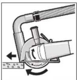
Prilikom primene usisne haube za presecanje sa vodećim šinama (24) mora da bude dozvoljen usisivač za usisavanje kamene prašine. Bosch nudi adekvatne usisivače.
natural_image
Mechanical diagram showing a tool interacting with a curved pipe and rotating component (no text or symbols)Uključite električni alat i prednjim delom vodećih šina ga stavite na radni komad. Električni alat pomičite ravnomerno, prilagođeno materijalu koji se obraduje.
Prilikom rezanja tvrdih materijala, npr. betona sa visokim sadržajem oblutka,
dijamantski disk za sečenje može da se pregreje i na taj način da se ošteti. Na to jasno ukazuje cirkularni venac varnica oko dijamantskog diska za sečenje.
U ovom slučaju prekinite rezanje i pustite dijamantski disk za sečenje da se u praznom hodu vrti kratko vreme na najviše obrtaja da bi se ohladio.
Napredak u radu koji primetno zaostaje i cirkularni venac varnica su znakovi da je dijamantski disk za sečenje postao tup. Isti možete da naoštrite kratkim rezovima u abrazivnom materijalu (npr. peščani kamen).
Napomene za statiku
www.bosch-pt.com/serviceaddresses
Transport
Akumulatorske baterije koje sadrže litijum jon podležu zahtevima prava o opasnim materijama. Akumulatorske
baterije korisnik može transportovati na drumu bez drugih pakovanja.
Kod slanja preko trećih lica (na primer vazdušnih transportom ili špedicijom) mora se obratiti pažnja na posebne zahteve u pogledu pakovanja i označavanja. Tada se kod pripreme paketa za slanje mora pozvati stručnjak za opasne materije.
Akumulatorske baterije šaljite samo ako kućište nije oštećeno. Odlepite otvorene kontakte i upakujte akumulatorsku bateriju tako, da se ne pokreće u paketu. Molimo da obratite pažnju na eventualne dalje nationalne propise.
Uklanjanje dubreta

Električne alate, akumulacione baterije, pribor i pakovanja treba predati na reciklažu koja je u skladu sa zaštitom životne sredine.

Ne bacajte električne alate i akumulatore/baterije u kućno djubre!
Samo za EU-zemlje:
Prema evropskoj smernici 2012/19/EU električni alati koji su neupotrebljivi, a prema evropskoj smernici 2006/66/EC ni akumulatori/baterije koji su u kvaru ili istrošeni, ne moraju više da se odvojeno sakupljaju i odvoze na reciklažu koja odgovara zaštiti čovekove sredine.
natural_image
Diagram of two mechanical components with curved arrows indicating rotation or motion (no text or symbols)natural_image
Diagram of a hand operating a mechanical disc with a rotating knob (no text or symbols)natural_image
Mechanical assembly diagram showing rotational motion with arrows indicating direction (no text or symbols)natural_image
Illustration of a robotic arm with a rotating head and motion arrows (no text or symbols)natural_image
Diagram of a mechanical device with rotating components and directional arrows (no text or symbols)www.bosch-pt.com/serviceaddresses
Transport
natural_image
Diagram of two mechanical components with curved arrows indicating rotation or motion (no text or symbols)Štitnik (10) stavite na grlo vretena. Prilagodite položaj štitnika (10) zahtjevima faze rada. Blokirajte štitnik (10) pritezanjem vijka za fiksiranje (9) pomoću šesterokutnog ključa (4).
▶ Štitnik (10) namjestite tako da se spriječi iskrenje u smjeru osobe koja radi s kutnom brusilicom.
Napomena: Kodirni izdanci na štitniku (10) osiguravaju da je moguća montaža samo štitnika koji odgovara električnom alatu.
Štitnik za rezanje
Kod rezanja s kompozitnim brusnim sredstvima uvijek koristite štitnik za rezanje (16).
Kod rezanja kamena treba osigurati dovoljno usisavanje prašine.
Štitnik za rezanje (16) montira se kao i štitnik za brušenje (10).
Usisni poklopac za rezanje s kliznom vodilicom
Usisni poklopac za rezanje s kliznom vodilicom (24) montira se kao i štitnik za brušenje (10).
Dodatna ručka
▶ Koristite svoj električni alat samo s dodatnom ručkom (7).
natural_image
Diagram of a hand operating a mechanical component with a rotating arrow (no text or symbols)Pravilno pričvršćenu, neoštećenu brzosteznu maticu možete ručno otpustiti okretanjem nazubljenog prstena u smjeru suprotnom od kazaljke na satu. Brzosteznu maticu s čvrstim dosjedom nikada ne otpuštajte kliještima, nego upotrijebite dvostruki okasti ključ. Stavite dvostruki okasti ključ kao što je prikazano na
slici.
Dopušteni brusni alati
Možete koristiti sve brusne alate navedene u ovim uputama za uporabu.
Dopušteni broj okretaja [min ^1 ] odnosno obodna brzina [m/s] korištenih brusnih alata mora barem odgovarati podacima u sljedećoj tablici.
Stoga se pridržavajte dopuštenog broja okretaja odnosno obodne brzine na naljepnici brusnog alata.
| maks. [mm] [mm] | |||||
| D b d [min] | ^-1 [m/s] | ||||
| 115 | 7 | 22,2 | 11000 | 80 | |
| 125 | 7 | 22,2 | 11000 | 80 | |
| 115 | - | - | 11000 | 80 | |
| 125 | - | - | 11000 | 80 | |
75 30 M 14 11000 45

natural_image
Mechanical assembly diagram showing rotational motion with arrows indicating direction (no text or symbols)natural_image
Illustration of a robotic arm interacting with a circular mechanical component (no text or symbols visible)Električni alat mora se uvijek voditi protuhodno. U suprotnom postoji opasnost da se nekontrolirano istisne iz reza. Kod rezanja profila i četverokutnih cijevi najbolje je da stavite na najmanji presjek.
Rezanje kamena
Kod rezanja kamena treba osigurati dovoljno usisavanje prašine.
▶ Nosite zaštitnu masku protiv prašine.
▶ Električni alat smije se koristiti samo za suho rezanje/suho brušenje.
Za rezanje kamena najbolje je koristiti dijamantnu reznu ploču.
Pri uporabi usisnog poklopca za rezanje s kliznom vodilicom (24) mora se koristiti odobreni usisavač za usisavanje kamene prašine. Bosch ima u ponudi prikladne usisavače prašine.

natural_image
Mechanical diagram showing a tool interacting with a curved pipe and rotating arm (no text or symbols)www.bosch-pt.com/serviceaddresses
Transport
a_n = 6,0m / s^2,K = 1,5m / s^2,
natural_image
Diagram of two mechanical components with curved arrows indicating rotation or motion (no text or symbols)natural_image
Diagram of a hand pressing a circular mechanical component with directional arrows (no text or symbols)natural_image
Mechanical assembly diagram showing a rotating component with directional arrows indicating motion (no text or symbols)natural_image
Illustration of a robotic arm with a curved arm and motion arrow (no text or symbols)natural_image
Mechanical diagram showing a tool interacting with a pipe and valve (no text or symbols)www.bosch-pt.com/serviceaddresses
Transport
natural_image
Mechanical diagram showing two rotating components with curved arrows indicating rotation direction (no text or symbols)natural_image
Diagram of a hand operating a mechanical component with a rotating arrow (no text or symbols)natural_image
Mechanical assembly diagram showing a rotating motor with directional arrows indicating motion (no text or symbols)natural_image
Illustration of a robotic arm performing a circular motion maneuver with directional arrows (no text or symbols)natural_image
Mechanical diagram showing a pipe connection with rotating components and directional arrows (no text or symbols)www.bosch-pt.com/serviceaddresses
Transportēšana
natural_image
Mechanical diagram showing two rotating components with curved arrows indicating rotation direction (no text or symbols)natural_image
Diagram of a hand operating a mechanical disc with a rotating wheel (no text or symbols)natural_image
Mechanical assembly diagram showing a gear mechanism with rotational arrows (no text or labels)natural_image
Illustration of a robotic arm with joints and motion arrows (no text or symbols)natural_image
Mechanical diagram showing a pipe clamp and rotating component with directional arrows (no text or symbols)www.bosch-pt.com/serviceaddresses
Transportavimas
natural_image
Mechanical diagram showing two rotating components with curved arrows indicating rotation direction (no text or symbols)"Electronic Cell Pro
ع التشفيل والإطفاء
natural_image
Mechanical diagram showing a pipe joint with rotating components and directional arrows (no text or symbols)natural_image
Illustration of a robotic arm with motion arrows indicating movement (no text or symbols)قطع الخدمات自贸区
Robert Bosch Morocco SARL
53 الملازم محمد م representatives
20300الدار البيضاء
:الهاتف+212 5 29 31 43 27
: Isav.outillage@ma.k
www.bosch-pt.com/serviceaddresses
النقل
text_image
Technical diagram showing two circular mechanical components with directional arrows indicating rotation or movement.natural_image
Mechanical assembly diagram showing a motor with rotating components and directional arrows (no text or labels)natural_image
Diagram of a hand operating a mechanical component with a rotating arrow and base, no text or symbols presentابزارهای مجاز ساب
natural_image
Mechanical diagram showing a robotic arm interacting with a ball on a platform, with no visible text or symbols.برش سنگ
natural_image
Diagram of a mechanical device with rotating components and directional arrows (no text or symbols)◀jā meaning (az) meaning (a)
www.bosch-pt.com/serviceaddresses
flowchart
graph TD
    A[" "] --> B["best expert standard"]
    A --> C["best for expert standard for"]
    A --> D["best for expert for standard for"]
    A --> E["best for expert for standard for"]
    A --> F["best for Inox metal expert for Metal"]
    A --> G["● DRYspeed best for Ceramic"]
314
text_image
1 605 703 099 SDS-clic 1 603 340 031 (M14) 1 603 340 040 1 607 950 043 1 602 025 024 1 601 329 013 2 608 900 000 1 601 329 013 Ø 115 mm Ø 125 mm 1 619 P06 547 1 619 P06 548 Ø 115 mm Ø 125 mm 1 619 P06 550 1 619 P06 551 1 600 793 007 1 619 P06 514 1 600 A00 3DHØ 125 mmCE
1
| de | EU-Konformitätserklärung | Wir erklären in alleiniger Verantwortung, dass die genannten Produkte allen einschlägigen Bestimmungen der nachfolgend aufgeführten Richtlinien und Verordnungen entsprechen und mit folgenden Normen übereinstimmen.Technische Unterlagen bei: * | |
| Winkelschleifer | Sachnummer | ||
| en | EU Declaration of Conformity | We declare under our sole responsibility that the stated products comply with all applicable provisions of the directives and regulations listed below and are in conformity with the following standards.Technical file at: * | |
| Angle grinder | Article number | ||
| fr | Déclaration de conformité UE | Nous déclarons sous notre propre responsabilité que les produits décrits sont en conformité avec les directives, règlements normatifs et normes énumérés ci-dessous.Dossier technique auprès de : * | |
| Meuleuse angulaire | N° d'article | ||
| es | Declaración de conformidad UE | Declaramos bajo nuestra exclusiva responsabilidad, que los productos nombrados cumplen con todas las disposiciones correspondientes de las Directivas y los Reglamentos mencionados a continuación y están en conformidad con las siguientes normas.Documentos técnicos de: * | |
| Amoladora angular | N° de artículo | ||
| pt | Declaração de Conformidade UE | Declaramos sob nossa exclusiva responsabilidade que os produtos mencionados cumprem todas as disposições e os regulamentos indicados e estão em conformidade com as seguintes normas.Documentação técnica pertencente à: * | |
| Rebarbadora | N.° do produto | ||
| it | Dichiarazione di conformità UE | Dichiariamo sotto la nostra piena responsabilità che i prodotti indicati sono conformi a tutte le disposizioni pertinenti delle Direttive e dei Regolamenti elencati di seguito, nonché alle seguenti Normative.Documentazione Tecnica presso: * | |
| Smerigliatrice an-golare | Codice prodotto | ||
| nl | EU-conformiteitsverklaring | Wij verklaren op eigen verantwoordelijkheid dat de genoemde producten voldoen aan alle desbetreffende bepalingen van de hierna genoemde richtlijnen en verordeningen en overeenstemmen met de volgende normen.Technisch dossier bij: * | |
| Haakse slijpmachine | Productnummer | ||
| da | EU-overensstemmelseserklæring | Vi erklærer som eneansvarlige, at det beskrevne produkt er i overensstemmelse med alle gældende bestemmelser i følgende direktiver og forordninger og opfylder følgende standarder.Tekniske bilag ved: * | |
| Vinkelsliber | Typenummer | ||
| sv | EU-konformitetsförklaring | Vi förklarar under eget ansvar att de nämnda produkterna uppfyller kraven i alla gällande bestämmelser i de nedan angivna direktiven och förordningar nas och att de stämmer överens med följande normer.Teknisk dokumentation: * | |
| Vinkelslip | Produktnummer | ||
| no | EU-samsvarserklæring | Vi erklærer under eneansvar at de nevnte produktene er i overensstemmelse med alle relevante bestemmelser i direktivene og forordningene nedenfor og med følgende standarder.Teknisk dokumentasjon hos: * | |
| Vinkelsliper | Produktnummer | ||
| fi | EU-vaatimustenmukaisuusvakuutus | Vakuutamme täten, että mainitut tuotteet vastaavat kaikkia seuraavien direktiivien ja asetusten asiaankuuluvia vaatimuksia ja ovat seuraavien standardien vaatimusten mukaisia.Tekniset asiakirjat saatavana: * | |
| Kulmahiomakone | Tuotenumero | ||
| el | Δήλωση πιστότητας EE | Δηλώνουμε με αποκλειστική μας ευθύνη, ότι τα αναφερόμενα προϊόντα αντιστοιχούν σε όλες τις σχετικές διατάξεις των πιο κάτω αναφερόμενων οδηγιών και κανονισμών και ταυτίζονται με τα ακόλουθα πρότυπα.Tεχνικά έγγραφα στη: * | |
| Γωνιακός λειαντήρας | Αριθμός ευρετηρίου | ||
| tr | AB Uygunluk beyani | Tek sorumlu olarak, tanımlanan ürünün aşağıdaki yönetmelik ve direktiflerin geçerli bütün hükümlerine ve aşağıdaki standartlara uygun olduğunu beyan ederiz.Teknik belgelerin bulunduğu yer: * | |
| Taşlama makinesi | Ürün kodu | ||
||
CE
| pl | Deklaracja zgodności UE | Oświadczamy z pełną odpowiedzialnością, że niniejsze produkty odpowiadają wszystkim wymaganiom poniżej wyszczególnionych dyrektyw i rozporządzeń, oraz że są zgodne z następującymi normami.Dokumentacja techniczna:* | |
| Szlifierka kątowa | Numer katalogowy | ||
| cs | EU prohlăšení oshodě | Prohlašujeme na výhradní zodpovědnost, že uvedený výrobek splňuje všechna příslušná ustanovení níže uvedených směrnic anařízení aje vsouladu snásledujícími normami:Technické podklady u:* | |
| Úhlová bruska | Objednaci číslo | ||
| sk | EÚ vyhlásenie ozhode | Vyhlasujeme na výhradní zodpovednosť, že uvedený výrobok splňa všetky príslušné ustanovenia nižšie uvedených smerníc anariadení aje vsúlade snasledujúcimi normami:Technické podklady má spoločnosť:* | |
| Uhlová brúska | Vecné číslo | ||
| hu | EU konformitási nyilatkozat | Egyedüli felelőséggel kijelentjük, hogy a megnevezett termékek megfelelnek az alábbiakban felsorolásra kerülő irányelvek és rendeletek valamennyi idevágó előírásainak és megfelelnek a következő szabványoknak.Műszaki dokumentumok megőrzési pontja:* | |
| Sarokcsiszoló | Cikkszám | ||
| ru | Заявление о соответствии EC | Мы заявляем под нашу единоличную ответственность, что названные продукты соответствуют всем действующим предписаниям нижеуказанных директив и распоряжений, а также нижеуказанных норм.Техническая документация хранится y:* | |
| Угловая шлифовальная машина | Товарный No | ||
| uk | Заява про відповідність ЄС | Мизаявляємо під нашу одноособову відповідальність, що названі вироби відповідають усім чинним положенням нищеозначених директив і розпоряджень, а також нижчеозначеним нормам.Технічна документація зберігається y:* | |
| Кутова шліфмашина | Товарний номер | ||
| kk | EO сәйкестік маглумдамасы | Өз жауапкершілікпен біз аталған өнімдер теменде жзылған директикалар мен жарлықтардың тиісті қағилаларына сәйкестігін және темендері нормаларға сай екенін білдіреміз.Техникалық құжаттар:* | |
| Бұрыштық тегістеу машинасы | Өнім нөмірі | ||
| ro | Declarație de conformitate UE | Declarăm pe proprie răspundere că produsele mentionate corespund tuturor dispozițiilor relevante ale directivelor și reglementărilor enumerate în cele ce urmează și sunt în conformitate cu următoarele standarde.Documentаție tehnică la:* | |
| Polizor unghiular | Număr de identificare | ||
| bg | ЕС декларация за съответствие | С пълна отговорност ние декларираме, че посочените продукти отговарят на всички валидни изисквания на директивите и разпоредбите по-долу и съответства на следните стандарти.Техническа документация при:* | |
| Ъглошлайф | Каталожен номер | ||
| mk | EU-Изјава за сообразност | Со целосна одговорност изјавуваме, дека опишаните производи се во согласност со сите релевантни одредби на следните регулативи и прописи и се во согласност со следните норми.Техничка документација кај:* | |
| Аголна брусилка | Број на дел/артик | ||
| sr | EU-izjava o usaglašenosti | Na sopstvenu odgovornost izjavljujemo, da navedeni proizvodi odgovaraju svim dotičnim odredbama naknadno navedenih smernica u uredaba i da su u skladu sa sledećim standardima.Tehnička dokumentacija kod:* | |
| Ugaona brusilica | Broj predmeta | ||
| sl | Izjava o skladnosti EU | Izjavljamo pod izključno odgovornostjo, da je omenjen izdelek v skladu z vse-mi relevantnimi določili direktiv in uredb ter ustreza naslednjim standardom. Tehnična dokumentacija pri:* | |
| Kotni brusilnik | Številka artikla | ||
| hr | EU izjava o sukladnosti | Pod punom odgovornošću izjavljujemo da navedeni proizvodi odgovaraju svim relevantnim odredbama direktiva i propisima navedenima u nastavku i da su sukladni sa sljedećim normama.Tehnička dokumentacija se može dobiti kod:* | |
| Kutna brusilica | Kataloški br. | ||
| et | EL-vastavusdeklaratsioon | Kinnitame ainuvastutajatena, et nimetatud tooted vastavad järgnevalt loetletud direktiivide ja määruste kõikidele asjaomastele nõuetele ja on kooskõlas | |
| Nurklihvmasin | Tootenumber | ||
CE
III
| järgmiste normidega.Tehnilised dokumendid saadaval: * | ||||
| Iv | Deklarācija par atbilstībuES standartiem | Mēs ar pilnu atbildību paziņojam, ka šeit aplūkotie izstrādājumi atbilst visiem tālāk minētajās direktīvās un rīkojumos ietvertajām saistošajām nostādnēm,kā arī sekojošiem standartiem.Tehniskā dokumentācija no: * | ||
| Lenka slīpmašina | Izstrādājuma numurs | |||
| It | ES atitikties deklaracija | Atsakingai pareiškiame, kad išvardyti gaminiai atitinka visus privalomus žemiau nurodytų direktyvų ir reglamentų reikalavimus ir šiuos standartus.Techninė dokumentacija saugoma: * | ||
| Kampinio šlifavimo mašina | Gaminio numeris | |||
| GWS 18 V-LI | 3 601 J3A 300 | 2006/42/EC | EN 60745-1:2009+A11:2010 | |
| GWS 18-125 V-LI | 3 601 J3A 301 | 2014/30/EU | EN 60745-2-3:2011+A2:2013+A11:2014+A12:2014+A13:2015EN 55014-1:2017+A11:2020EN 55014-2:2015EN IEC 63000:2018 | |
| 2011/65/EU | ||||
 | BOSCH* Robert Bosch Power Tools GmbH(PT/ECS)70538 StuttgartGERMANY | |||
Henk BeckerChairman of Executive Management Robert Bosch Power Tools GmbH, 70538 Stuttgart, GERMANYStuttgart, 06.07.2020 Robert Bosch Power Tools GmbH, 70538 Stuttgart, GERMANYStuttgart, 06.07.2020 | Helmut HeinzelmannHead of Product Certification | |||